2015 HYUNDAI I30 tow
[x] Cancel search: towPage 125 of 635

447
Features of your vehicle
Engine coolant temperature warninglight (if equipped)
The warning light shows the temperature of the engine coolant when the ignition
switch is ON.
The warning light illuminates if the tem-
perature of the engine coolant is above
120°C (248°F) and the warning light
turns off if the temperature of the engine
coolant is below 115°C (239°F).
Do not continue driving with an overheat-
ed engine. If your vehicle overheats, refer
to “Overheating” in section 6.
✽✽ NOTICE
If the engine coolant temperature warn- ing light illuminates, it indicates over-heating that may damage the engine.
D150308AFD
Parking brake & brake fluid warning
Parking brake warning
This light is illuminated when the parking
brake is applied with the ignition switch in
the START or ON position. The warning
light should go off when the parking
brake is released. Low brake fluid level warning
If the warning light remains on, it may
indicate that the brake fluid level in the
reservoir is low.
If the warning light remains on:
1. Drive carefully to the nearest safe location and stop your vehicle.
2. With the engine stopped, check the brake fluid level immediately and add
fluid as required. Then check all brake
components for fluid leaks.
3. Do not drive the vehicle if leaks are found, the warning light remains on or
the brakes do not operate properly.
Have it towed to any authorized
HYUNDAI dealer for a brake system
inspection and necessary repairs. Your vehicle is equipped with dual-diago-
nal braking systems. This means you still
have braking on two wheels even if one
of the dual systems should fail. With only
one of the dual systems working, more
than normal pedal travel and greaterpedal pressure are required to stop the
car. Also, the car will not stop in as short
a distance with only a portion of the
brake system working. If the brakes fail
while you are driving, shift to a lower gear
for additional engine braking and stop the
car as soon as it is safe to do so.
To check bulb operation, check whether
the parking brake and brake fluid warning
light illuminates when the ignition switchis in the ON position.
WARNING
Driving the vehicle with a warning
light on is dangerous. If the brake
warning light remains on, have the
brakes checked and repaired imme-
diately by an authorized HYUNDAI
dealer.
Page 134 of 635
Features of your vehicle
56
4
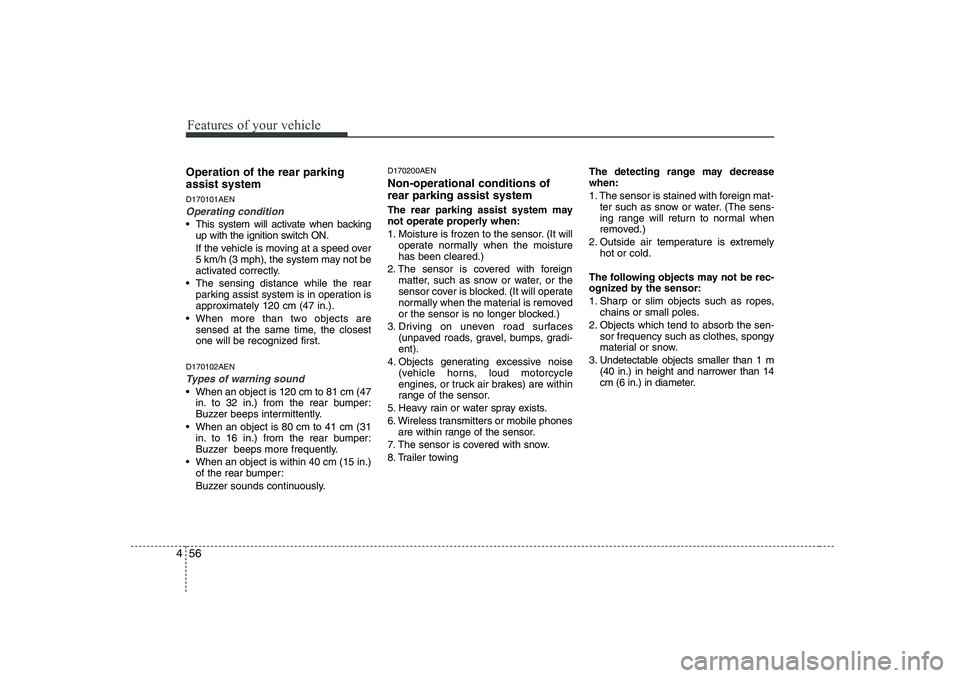
Operation of the rear parking assist system D170101AEN
Operating condition
This system will activate when backing
up with the ignition switch ON.
If the vehicle is moving at a speed over
5 km/h (3 mph), the system may not be
activated correctly.
The sensing distance while the rear parking assist system is in operation is
approximately 120 cm (47 in.).
When more than two objects are sensed at the same time, the closest
one will be recognized first.
D170102AEN
Types of warning sound
When an object is 120 cm to 81 cm (47 in. to 32 in.) from the rear bumper:
Buzzer beeps intermittently.
When an object is 80 cm to 41 cm (31 in. to 16 in.) from the rear bumper:
Buzzer beeps more frequently.
When an object is within 40 cm (15 in.) of the rear bumper:
Buzzer sounds continuously. D170200AEN Non-operational conditions of rear parking assist system
The rear parking assist system may
not operate properly when:
1. Moisture is frozen to the sensor. (It will
operate normally when the moisture has been cleared.)
2. The sensor is covered with foreign matter, such as snow or water, or the
sensor cover is blocked. (It will operate
normally when the material is removed
or the sensor is no longer blocked.)
3. Driving on uneven road surfaces (unpaved roads, gravel, bumps, gradi-ent).
4. Objects generating excessive noise (vehicle horns, loud motorcycle
engines, or truck air brakes) are within
range of the sensor.
5. Heavy rain or water spray exists.
6. Wireless transmitters or mobile phones are within range of the sensor.
7. The sensor is covered with snow.
8. Trailer towing The detecting range may decrease when:
1. The sensor is stained with foreign mat-
ter such as snow or water. (The sens-
ing range will return to normal when
removed.)
2. Outside air temperature is extremely hot or cold.
The following objects may not be rec-
ognized by the sensor:
1. Sharp or slim objects such as ropes, chains or small poles.
2. Objects which tend to absorb the sen- sor frequency such as clothes, spongy
material or snow.
3. Undetectable objects smaller than 1 m (40 in.) in height and narrower than 14
cm (6 in.) in diameter.
Page 140 of 635
Features of your vehicle
62
4
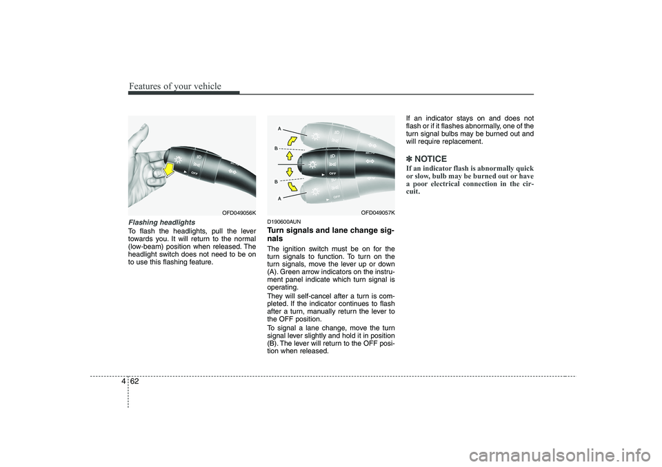
Flashing headlights
To flash the headlights, pull the lever
towards you. It will return to the normal
(low-beam) position when released. The
headlight switch does not need to be on
to use this flashing feature. D190600AUN
Turn signals and lane change sig- nals
The ignition switch must be on for the
turn signals to function. To turn on the
turn signals, move the lever up or down
(A). Green arrow indicators on the instru-
ment panel indicate which turn signal is
operating.
They will self-cancel after a turn is com-
pleted. If the indicator continues to flash
after a turn, manually return the lever tothe OFF position.
To signal a lane change, move the turn
signal lever slightly and hold it in position
(B). The lever will return to the OFF posi-tion when released.If an indicator stays on and does not
flash or if it flashes abnormally, one of the
turn signal bulbs may be burned out andwill require replacement.
✽✽
NOTICE
If an indicator flash is abnormally quick
or slow, bulb may be burned out or have
a poor electrical connection in the cir-cuit.
OFD049057KOFD049056K
Page 145 of 635

467
Features of your vehicle
D200200AFD
Windshield washers
In the O (OFF) position, pull the lever
gently toward you to spray washer fluid
on the windshield and to run the wipers
1-3 cycles. Use this function when the
windshield is dirty. The spray and wiper
operation will continue until you release
the lever. If the washer does not work,
check the washer fluid level. If the fluid
level is not sufficient, you will need to add
appropriate non-abrasive windshield
washer fluid to the washer reservoir.
The reservoir filler neck is located in the
front of the engine compartment on the
passenger side.D200300AFD
Rear window wiper and washer
switch (if equipped)
The rear window wiper and washer
switch is located at the end of the wiper
and washer switch lever. Turn the switch
to desired position to operate the rear
wiper and washer.
- Spraying washer fluid and wiping
/ ON - Normal wiper operation
O / OFF - Wiper is not in operation - Spraying washer fluid and wiping
CAUTION
When washing the vehicle, set thewiper switch in the O (OFF) position
to stop the auto wiper operation.
The wiper may operate and be dam-aged if the switch is set in the AUTOmode while washing the vehicle.
Do not remove the sensor coverlocated on the upper end of the pas-senger side windshield glass. Damage to system parts couldoccur and may not be covered by
your vehicle warranty.
When starting the vehicle in winter,set the wiper switch in the O (OFF)position. Otherwise, wipers may
operate and ice may damage thewindshield wiper blades. Always remove all snow and ice and defrostthe windshield properly prior to
operating the windshield wipers.
CAUTION
To prevent possible damage to the washer pump, do not operate thewasher when the fluid reservoir is empty.
WARNING
Do not use the washer in freezing
temperatures without first warming
the windshield with the defrosters;
the washer solution could freeze oncontact with the windshield and
obscure your vision.
CAUTION
To prevent possible damage to the wipers or windshield, do not
operate the wipers when thewindshield is dry.
To prevent damage to the wiper blades, do not use gasoline,
kerosene, paint thinner, or othersolvents on or near them.
To prevent damage to the wiper arms and other components, donot attempt to move the wipers
manually.
Page 152 of 635
Features of your vehicle
74
4
D230101AFD
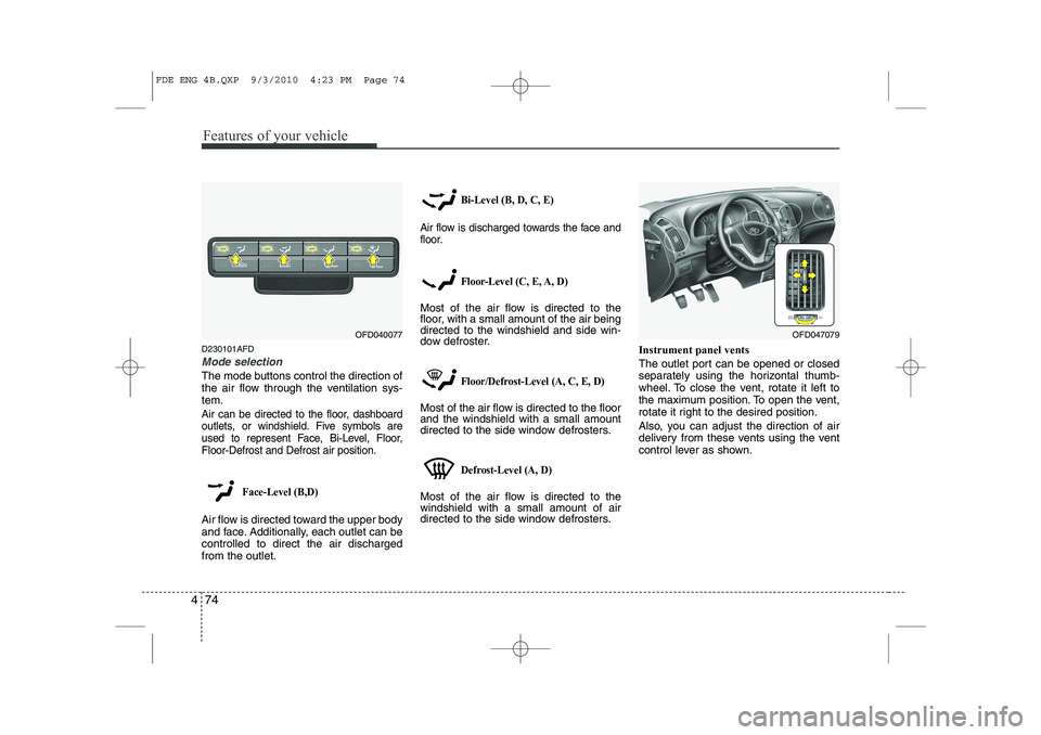
Mode selection
The mode buttons control the direction of
the air flow through the ventilation sys-tem.
Air can be directed to the floor, dashboard
outlets, or windshield. Five symbols are
used to represent Face, Bi-Level, Floor,Floor-Defrost and Defrost air position.
Face-Level (B,D)
Air flow is directed toward the upper body
and face. Additionally, each outlet can becontrolled to direct the air dischargedfrom the outlet.
Bi-Level (B, D, C, E)
Air flow is discharged towards the face and
floor.
Floor-Level (C, E, A, D)
Most of the air flow is directed to the
floor, with a small amount of the air beingdirected to the windshield and side win-
dow defroster.
Floor/Defrost-Level (A, C, E, D)
Most of the air flow is directed to the floorand the windshield with a small amount
directed to the side window defrosters.
Defrost-Level (A, D)
Most of the air flow is directed to thewindshield with a small amount of air
directed to the side window defrosters. Instrument panel vents
The outlet port can be opened or closed
separately using the horizontal thumb-
wheel. To close the vent, rotate it left to
the maximum position. To open the vent,
rotate it right to the desired position.
Also, you can adjust the direction of air
delivery from these vents using the vent
control lever as shown.
OFD040077OFD047079
FDE ENG 4B.QXP 9/3/2010 4:23 PM Page 74
Page 161 of 635
483
Features of your vehicle
D240200AUN
Manual heating and air condition- ing The heating and cooling system can be
controlled manually by pushing buttons
other than the AUTO button. In this case,
the system works sequentially according
to the order of buttons selected.
When pressing any button (or turning
any knob) except AUTO button while
automatic operation, the functions not
selected will be controlled automatically.
1. Start the engine.
2. Set the mode to the desired position.
3. Set the temperature control to thedesired position.
4. Set the air intake control to the outside (fresh) air position.
5. Set the fan speed control to the desired speed.
6. If air conditioning is desired, turn the air conditioning system on.
Press the AUTO button in order to con-
vert to full automatic control of the sys-tem. D240201AFD
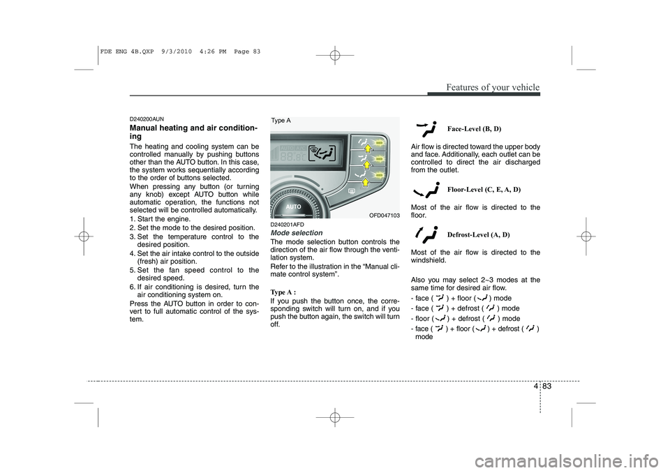
Mode selection
The mode selection button controls the
direction of the air flow through the venti-lation system.
Refer to the illustration in the “Manual cli- mate control system”.
Type A :
If you push the button once, the corre-
sponding switch will turn on, and if you
push the button again, the switch will turn
off. Face-Level (B, D)
Air flow is directed toward the upper body
and face. Additionally, each outlet can becontrolled to direct the air dischargedfrom the outlet.
Floor-Level (C, E, A, D)
Most of the air flow is directed to the
floor.
Defrost-Level (A, D)
Most of the air flow is directed to thewindshield.
Also you may select 2~3 modes at the
same time for desired air flow.
- face ( ) + floor ( ) mode
- face ( ) + defrost ( ) mode
- floor ( ) + defrost ( ) mode
- face ( ) + floor ( ) + defrost ( ) mode
Type A
OFD047103
FDE ENG 4B.QXP 9/3/2010 4:26 PM Page 83
Page 162 of 635
Features of your vehicle
84
4
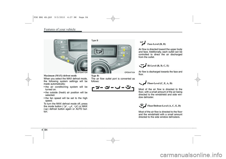
Maximum (MAX) defrost mode
When you select the MAX defrost mode,
the following system settings will bemade automatically;
the air conditioning system will be
turned on.
the outside (fresh) air position will be selected.
the fan speed will be set to the high speed.
To turn the MAX defrost mode off, press
the mode button ( , , ) or MAX
( ) defrost button again or AUTO but-ton. Type B:
The air flow outlet port is converted as
follows: Face-Level (B, D)
Air flow is directed toward the upper body
and face. Additionally, each outlet can becontrolled to direct the air dischargedfrom the outlet.
Bi-Level (B, D, C, E)
Air flow is discharged towards the face and
floor.
Floor-Level (C, E, A, D)
Most of the air flow is directed to the
floor, with a small amount of the air beingdirected to the windshield and side win-
dow defroster.
Floor/Defrost-Level (A, C, E, D)
Most of the air flow is directed to the floorand the windshield with a small amount
directed to the side window defrosters.
OFD047124OFD047104
Type B
FDE ENG 4B.QXP 9/3/2010 4:27 PM Page 84
Page 183 of 635
4 105
Features of your vehicle
D290300AFD
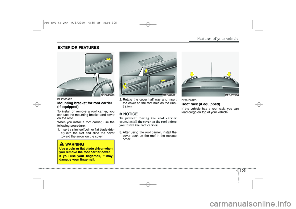
Mounting bracket for roof carrier (if equipped)
To install or remove a roof carrier, you
can use the mounting bracket and cover
on the roof.
When you install a roof carrier, use the
following procedure.
1. Insert a slim tool(coin or flat blade driv-er) into the slot and slide the cover
toward the arrow on the cover. 2. Rotate the cover half way and insert
the cover on the roof hole as the illus-
tration.
✽✽ NOTICE
To prevent loosing the roof carrier
cover, install the cover on the roof before
you install the roof carrier.
3. After using the roof carrier, install the cover back on the roof in the reverse
order. D290100AFD
Roof rack (if equipped)
If the vehicle has a roof rack, you can
load cargo on top of your vehicle.
EXTERIOR FEATURES
OED046090OED046091
WARNING
Use a coin or flat blade driver when
you remove the roof carrier cover.
If you use your fingernail, it may
damage your fingernail.
OED037106
FDE ENG 4B.QXP 9/3/2010 4:35 PM Page 105