2015 FORD POLICE INTERCEPTOR SEDAN air condition
[x] Cancel search: air conditionPage 205 of 401
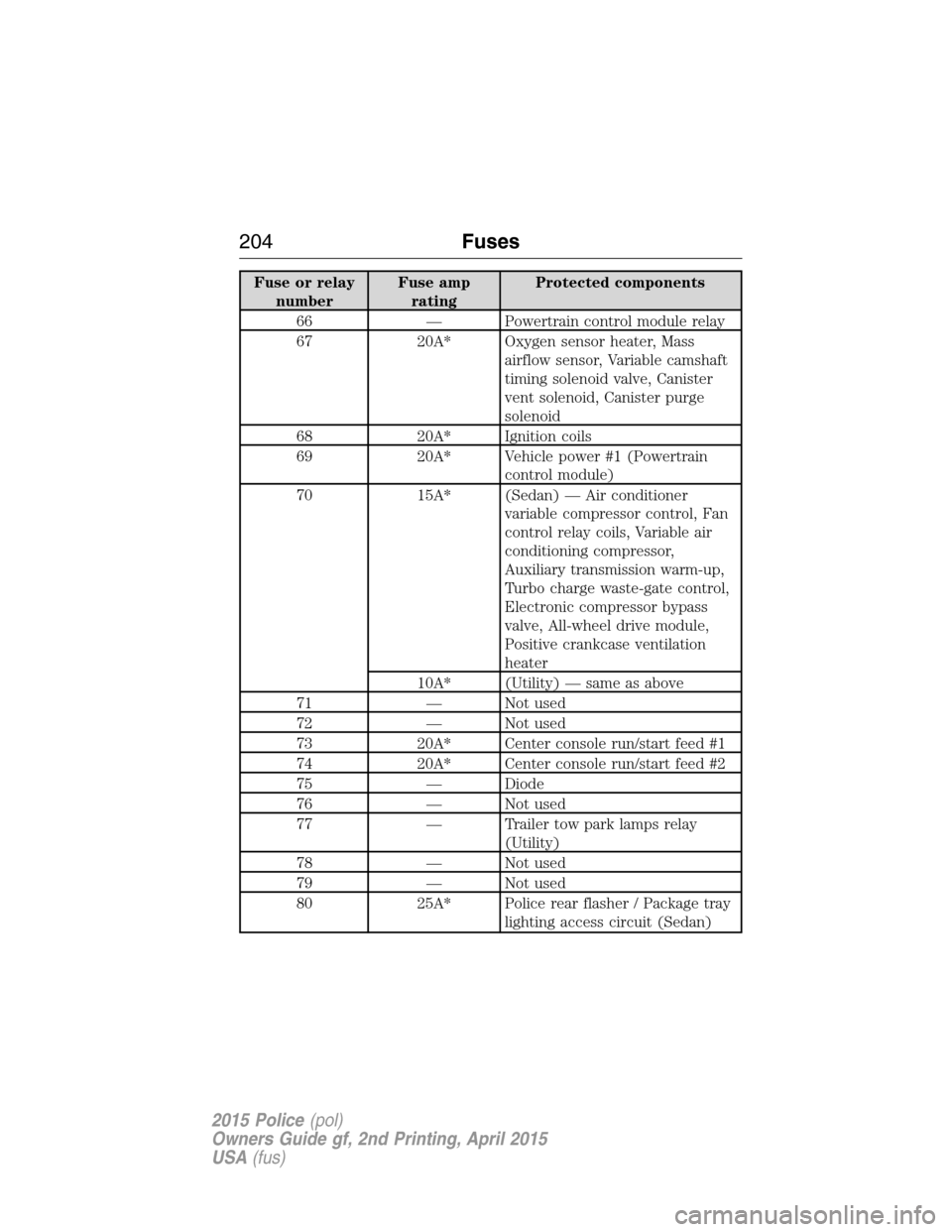
Fuse or relay
numberFuse amp
ratingProtected components
66 — Powertrain control module relay
67 20A* Oxygen sensor heater, Mass
airflow sensor, Variable camshaft
timing solenoid valve, Canister
vent solenoid, Canister purge
solenoid
68 20A* Ignition coils
69 20A* Vehicle power #1 (Powertrain
control module)
70 15A* (Sedan) — Air conditioner
variable compressor control, Fan
control relay coils, Variable air
conditioning compressor,
Auxiliary transmission warm-up,
Turbo charge waste-gate control,
Electronic compressor bypass
valve, All-wheel drive module,
Positive crankcase ventilation
heater
10A* (Utility) — same as above
71 — Not used
72 — Not used
73 20A* Center console run/start feed #1
74 20A* Center console run/start feed #2
75 — Diode
76 — Not used
77 — Trailer tow park lamps relay
(Utility)
78 — Not used
79 — Not used
80 25A* Police rear flasher / Package tray
lighting access circuit (Sedan)
204Fuses
2015 Police(pol)
Owners Guide gf, 2nd Printing, April 2015
USA(fus)
Page 206 of 401
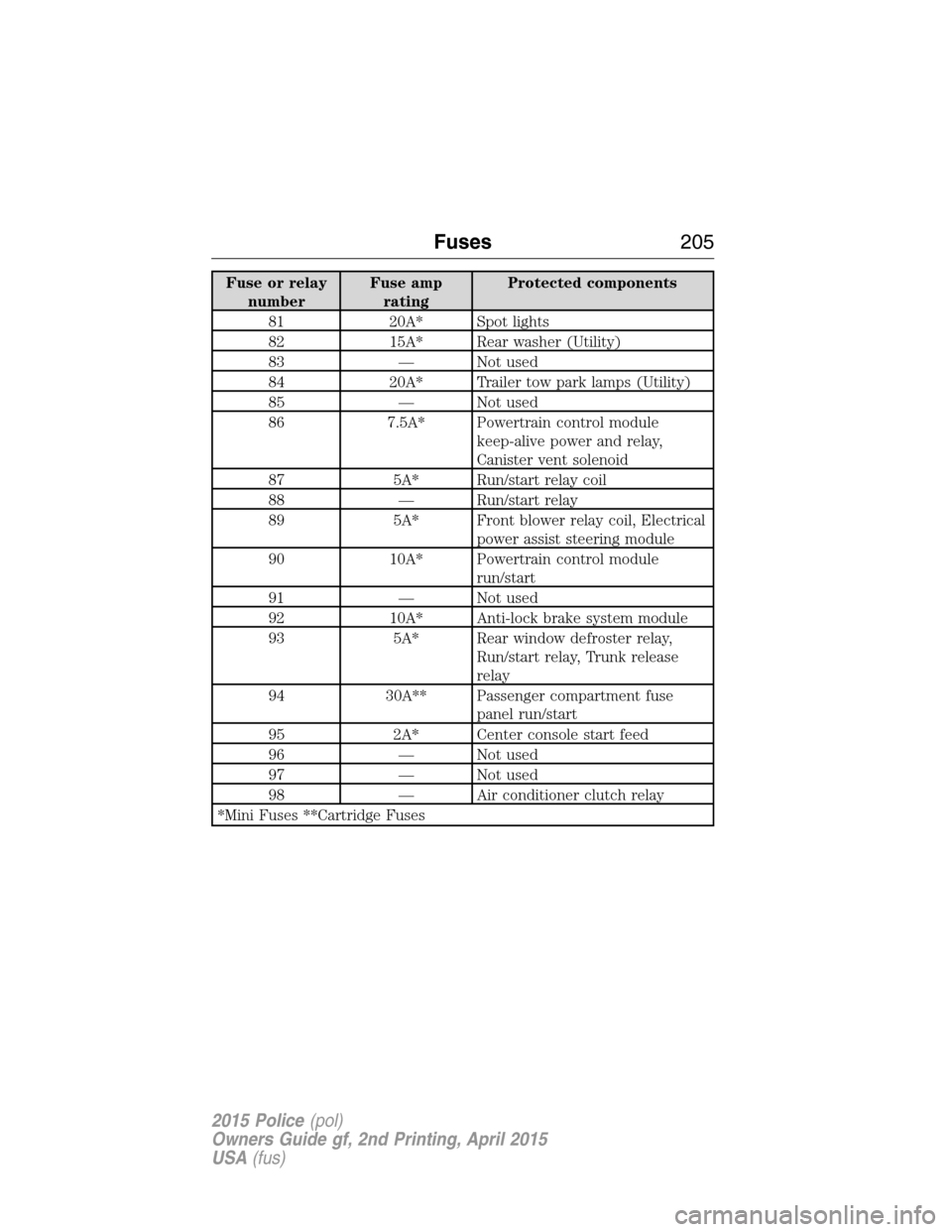
Fuse or relay
numberFuse amp
ratingProtected components
81 20A* Spot lights
82 15A* Rear washer (Utility)
83 — Not used
84 20A* Trailer tow park lamps (Utility)
85 — Not used
86 7.5A* Powertrain control module
keep-alive power and relay,
Canister vent solenoid
87 5A* Run/start relay coil
88 — Run/start relay
89 5A* Front blower relay coil, Electrical
power assist steering module
90 10A* Powertrain control module
run/start
91 — Not used
92 10A* Anti-lock brake system module
93 5A* Rear window defroster relay,
Run/start relay, Trunk release
relay
94 30A** Passenger compartment fuse
panel run/start
95 2A* Center console start feed
96 — Not used
97 — Not used
98 — Air conditioner clutch relay
*Mini Fuses **Cartridge Fuses
Fuses205
2015 Police(pol)
Owners Guide gf, 2nd Printing, April 2015
USA(fus)
Page 222 of 401
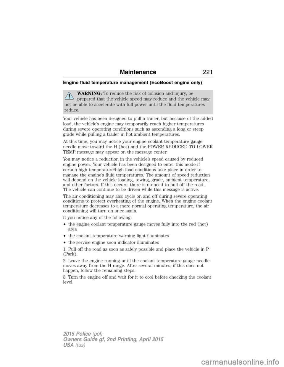
Engine fluid temperature management (EcoBoost engine only)
WARNING:To reduce the risk of collision and injury, be
prepared that the vehicle speed may reduce and the vehicle may
not be able to accelerate with full power until the fluid temperatures
reduce.
Your vehicle has been designed to pull a trailer, but because of the added
load, the vehicle’s engine may temporarily reach higher temperatures
during severe operating conditions such as ascending a long or steep
grade while pulling a trailer in hot ambient temperatures.
At this time, you may notice your engine coolant temperature gauge
needle move toward the H (hot) and the POWER REDUCED TO LOWER
TEMP message may appear on the message center.
You may notice a reduction in the vehicle’s speed caused by reduced
engine power. Your vehicle has been designed to enter this mode if
certain high temperature/high load conditions take place in order to
manage the engine’s fluid temperatures. The amount of speed reduction
will depend on the vehicle loading, towing, grade, ambient temperature,
and other factors. If this occurs, there is no need to pull off the road.
The vehicle can continue to be driven while this message is active.
The air conditioning may also cycle on and off during severe operating
conditions to protect overheating of the engine. When the engine coolant
temperature decreases to a more normal operating temperature, the air
conditioning will turn on once again.
If you notice any of the following:
•the engine coolant temperature gauge moves fully into the red (hot)
area
•the coolant temperature warning light illuminates
•the service engine soon indicator illuminates
1. Pull off the road as soon as safely possible and place the vehicle in P
(Park).
2. Leave the engine running until the coolant temperature gauge needle
moves away from the H range. After several minutes, if this does not
happen, follow the remaining steps.
3. Turn the engine off and wait for it to cool before checking the coolant
level.
Maintenance221
2015 Police(pol)
Owners Guide gf, 2nd Printing, April 2015
USA(fus)
Page 223 of 401
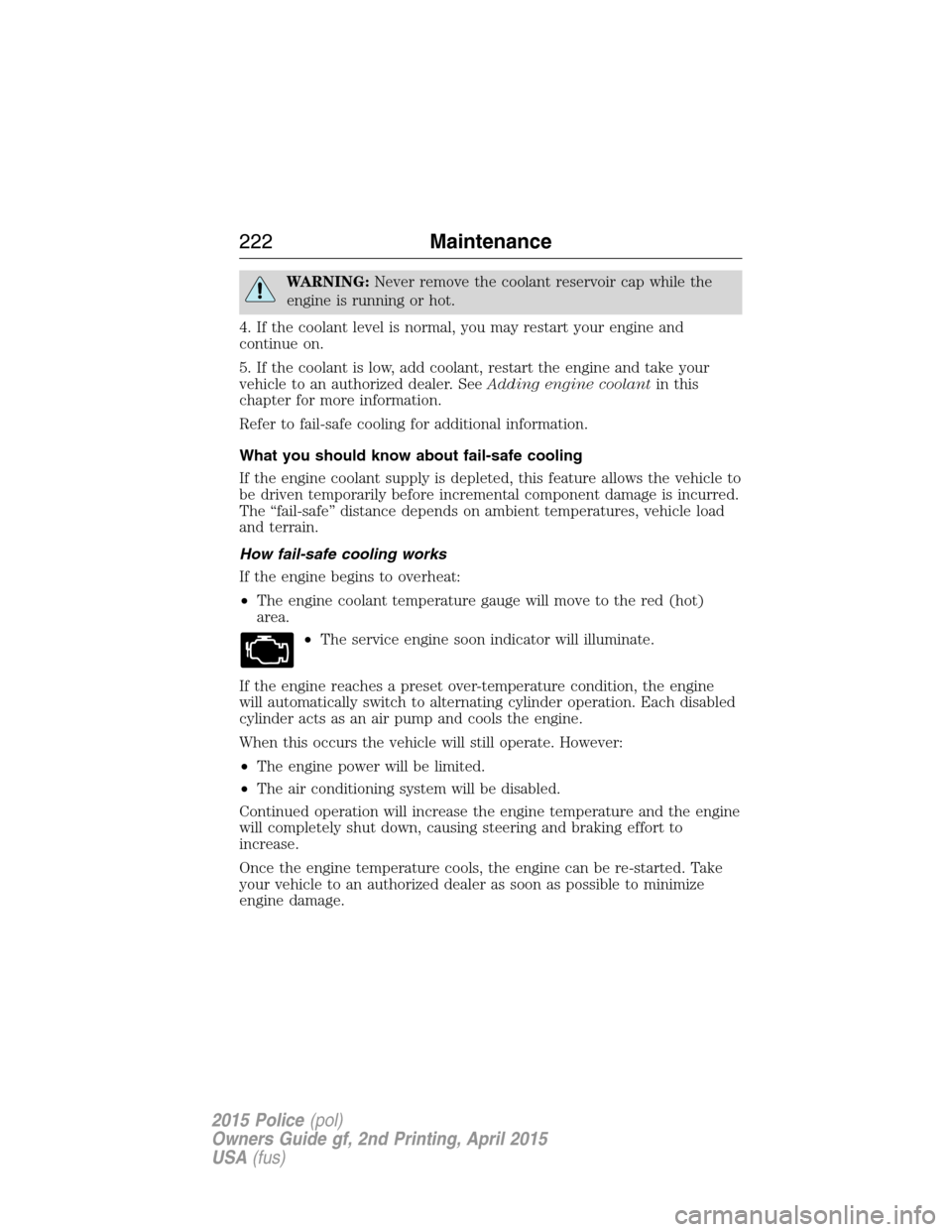
WARNING:Never remove the coolant reservoir cap while the
engine is running or hot.
4. If the coolant level is normal, you may restart your engine and
continue on.
5. If the coolant is low, add coolant, restart the engine and take your
vehicle to an authorized dealer. SeeAdding engine coolantin this
chapter for more information.
Refer to fail-safe cooling for additional information.
What you should know about fail-safe cooling
If the engine coolant supply is depleted, this feature allows the vehicle to
be driven temporarily before incremental component damage is incurred.
The “fail-safe” distance depends on ambient temperatures, vehicle load
and terrain.
How fail-safe cooling works
If the engine begins to overheat:
•The engine coolant temperature gauge will move to the red (hot)
area.
•The service engine soon indicator will illuminate.
If the engine reaches a preset over-temperature condition, the engine
will automatically switch to alternating cylinder operation. Each disabled
cylinder acts as an air pump and cools the engine.
When this occurs the vehicle will still operate. However:
•The engine power will be limited.
•The air conditioning system will be disabled.
Continued operation will increase the engine temperature and the engine
will completely shut down, causing steering and braking effort to
increase.
Once the engine temperature cools, the engine can be re-started. Take
your vehicle to an authorized dealer as soon as possible to minimize
engine damage.
222Maintenance
2015 Police(pol)
Owners Guide gf, 2nd Printing, April 2015
USA(fus)
Page 227 of 401
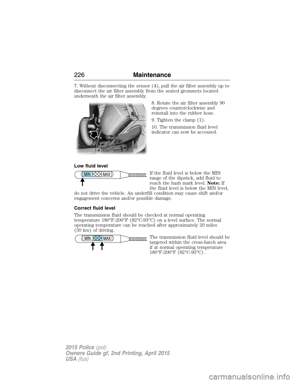
7. Without disconnecting the sensor (4), pull the air filter assembly up to
disconnect the air filter assembly from the seated grommets located
underneath the air filter assembly.
8. Rotate the air filter assembly 90
degrees counterclockwise and
reinstall into the rubber hose.
9. Tighten the clamp (1).
10. The transmission fluid level
indicator can now be accessed.
Low fluid level
If the fluid level is below the MIN
range of the dipstick, add fluid to
reach the hash mark level.Note:If
the fluid level is below the MIN level,
do not drive the vehicle. An underfill condition may cause shift and/or
engagement concerns and/or possible damage.
Correct fluid level
The transmission fluid should be checked at normal operating
temperature 180°F-200°F (82°C-93°C) on a level surface. The normal
operating temperature can be reached after approximately 20 miles
(30 km) of driving.
The transmission fluid level should be
targeted within the cross-hatch area
if at normal operating temperature
180°F-200°F (82°C-93°C) .
MAX MIN
226Maintenance
2015 Police(pol)
Owners Guide gf, 2nd Printing, April 2015
USA(fus)
Page 238 of 401
CHANGING A BULB
Lamp Assembly Condensation
Exterior lamps are vented to accommodate normal changes in pressure.
Condensation can be a natural by-product of this design. When moist air
enters the lamp assembly through the vents, there is a possibility that
condensation can occur when the temperature is cold. When normal
condensation occurs, a thin film of mist can form on the interior of the
lens. The thin mist eventually clears and exits through the vents during
normal operation. Clearing time may take as long as 48 hours under dry
weather conditions.
These are examples of acceptable condensation:
•Presence of thin mist (no streaks, drip marks or droplets).
•Fine mist covers less than 50% of the lens.
These are examples of unacceptable moisture (usually caused by a lamp
water leak):
•Water puddle inside the lamp.
•Large water droplets, drip marks or streaks present on the interior of
the lens.
Take your vehicle to a dealer for service if any of the above conditions of
unacceptable moisture are present.
Replacing headlamp bulbs
WARNING:Handle a halogen headlamp bulb carefully and keep
out of children’s reach. Grasp the bulb only by its plastic base
and do not touch the glass. The oil from your hand could cause the
bulb to break the next time the headlamps are operated.
Note:If the bulb is accidentally touched, it should be cleaned with
rubbing alcohol before being used.
Maintenance237
2015 Police(pol)
Owners Guide gf, 2nd Printing, April 2015
USA(fus)
Page 271 of 401
Note:Some spare tires operate at a higher inflation pressure than the
other tires. For T-type mini-spare tires, see theDissimilar Spare Tire
and Wheel Assembly Informationsection. Store and maintain at 60 psi
(4.15 bar). For full-size and dissimilar spare tires, seeDissimilar Spare
Tire and Wheel Assembly InformationunderChanging a Road Wheel
in this chapter. Store and maintain at the higher of the front and rear
inflation pressure as shown on the Tire Label.
6. Visually inspect the tires to make sure there are no nails or other objects
embedded that could poke a hole in the tire and cause an air leak.
7. Check the sidewalls to make sure there are no gouges, cuts or bulges.
Inspecting Your Tires and Wheel Valve Stems
Periodically inspect the tire treads for uneven or excessive wear and
remove objects such as stones, nails or glass that may be wedged in the
tread grooves. Check the tire and valve stems for holes, cracks, or cuts
that may permit air leakage and repair or replace the tire and replace
the valve stem. Inspect the tire sidewalls for cracking, cuts, bruises and
other signs of damage or excessive wear. If internal damage to the tire is
suspected, have the tire demounted and inspected in case it needs to be
repaired or replaced. For your safety, tires that are damaged or show
signs of excessive wear should not be used because they are more likely
to blow out or fail.
Improper or inadequate vehicle maintenance can cause tires to wear
abnormally. Inspect all your tires, including the spare, frequently, and
replace them if one or more of the following conditions exist:
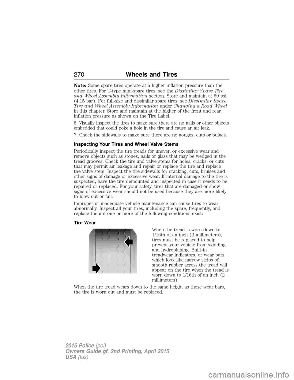
Tire Wear
When the tread is worn down to
1/16th of an inch (2 millimeters),
tires must be replaced to help
prevent your vehicle from skidding
and hydroplaning. Built-in
treadwear indicators, or wear bars,
which look like narrow strips of
smooth rubber across the tread will
appear on the tire when the tread is
worn down to 1/16th of an inch (2
millimeters).
When the tire tread wears down to the same height as these wear bars,
the tire is worn out and must be replaced.
270Wheels and Tires
2015 Police(pol)
Owners Guide gf, 2nd Printing, April 2015
USA(fus)
Page 302 of 401
Items CapacityRecommended Fluids
and LubricantsFord part number /
Ford specification
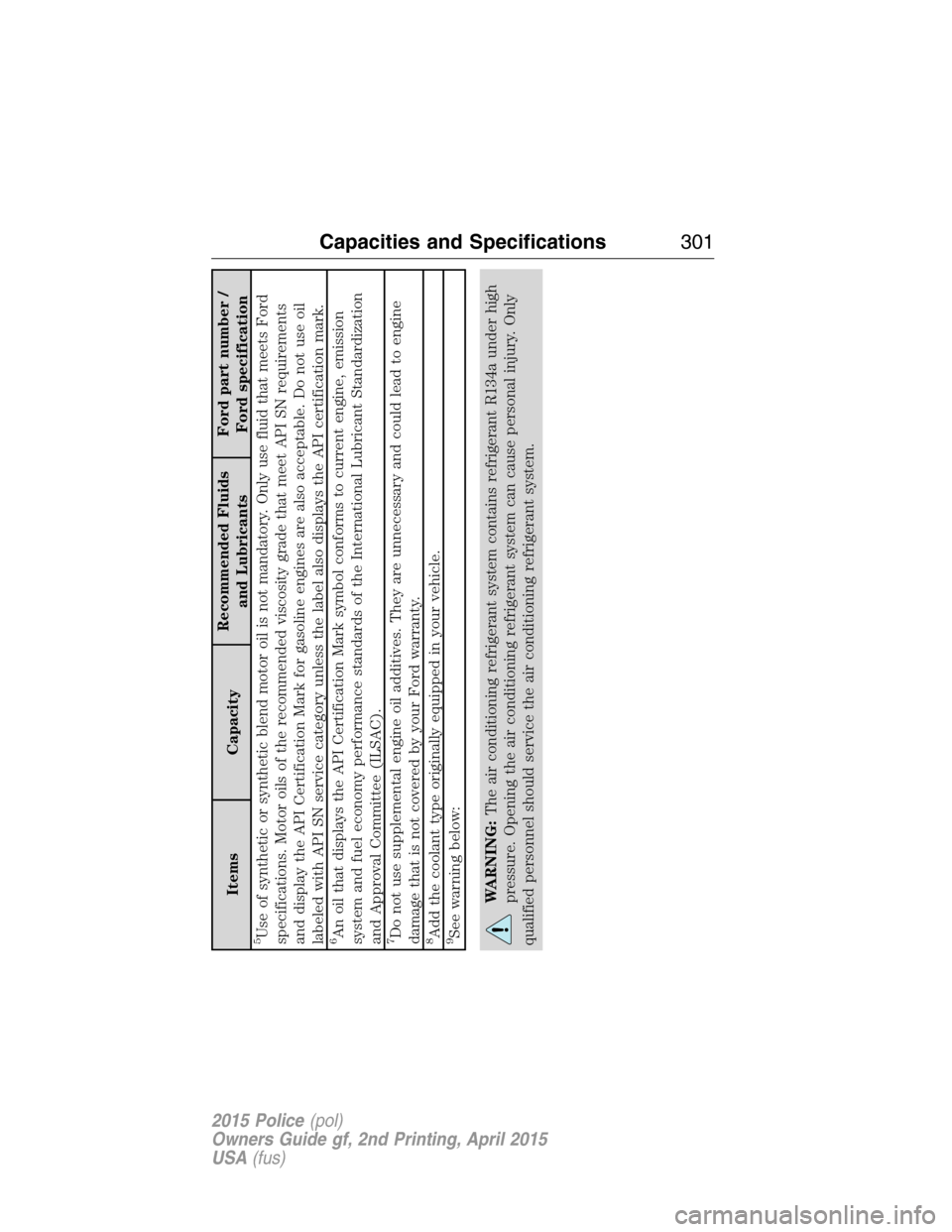
5Use of synthetic or synthetic blend motor oil is not mandatory. Only use fluid that meets Ford
specifications. Motor oils of the recommended viscosity grade that meet API SN requirements
and display the API Certification Mark for gasoline engines are also acceptable. Do not use oil
labeled with API SN service category unless the label also displays the API certification mark.6An oil that displays the API Certification Mark symbol conforms to current engine, emission
system and fuel economy performance standards of the International Lubricant Standardization
and Approval Committee (ILSAC).7Do not use supplemental engine oil additives. They are unnecessary and could lead to engine
damage that is not covered by your Ford warranty.8Add the coolant type originally equipped in your vehicle.9See warning below:
WARNING:The air conditioning refrigerant system contains refrigerant R134a under high
pressure. Opening the air conditioning refrigerant system can cause personal injury. Only
qualified personnel should service the air conditioning refrigerant system.
Capacities and Specifications301
2015 Police(pol)
Owners Guide gf, 2nd Printing, April 2015
USA(fus)