2015 FORD POLICE INTERCEPTOR SEDAN service indicator
[x] Cancel search: service indicatorPage 136 of 401
On-board Diagnostics (OBD-II)
Your vehicle is equipped with a computer that monitors the engine’s
emission control system. This system is commonly known as the
on-board diagnostics system (OBD-II). The OBD-II system protects the
environment by ensuring that your vehicle continues to meet
government emission standards. The OBD-II system also assists your
authorized dealer in properly servicing your vehicle.
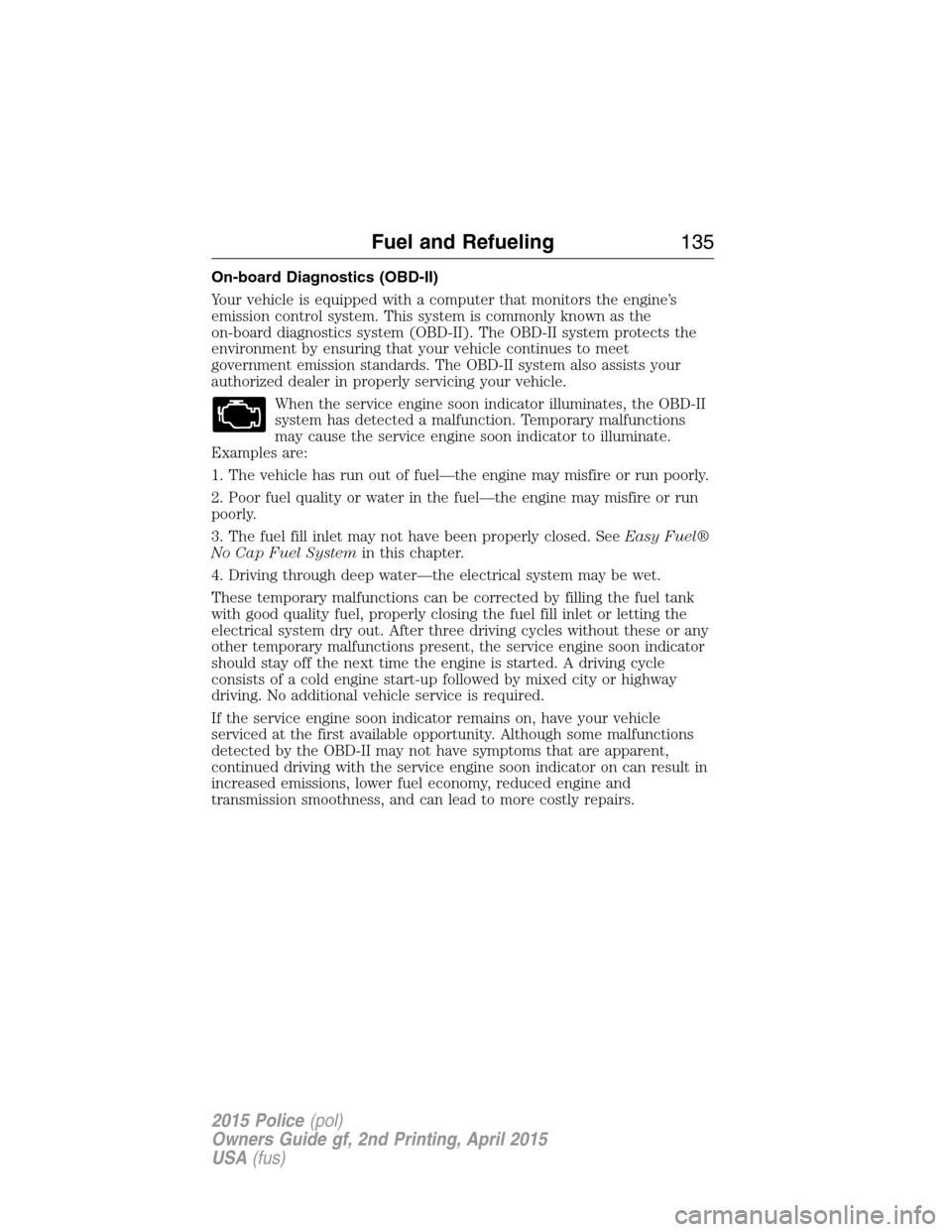
When the service engine soon indicator illuminates, the OBD-II
system has detected a malfunction. Temporary malfunctions
may cause the service engine soon indicator to illuminate.
Examples are:
1. The vehicle has run out of fuel—the engine may misfire or run poorly.
2. Poor fuel quality or water in the fuel—the engine may misfire or run
poorly.
3. The fuel fill inlet may not have been properly closed. SeeEasy Fuel®
No Cap Fuel Systemin this chapter.
4. Driving through deep water—the electrical system may be wet.
These temporary malfunctions can be corrected by filling the fuel tank
with good quality fuel, properly closing the fuel fill inlet or letting the
electrical system dry out. After three driving cycles without these or any
other temporary malfunctions present, the service engine soon indicator
should stay off the next time the engine is started. A driving cycle
consists of a cold engine start-up followed by mixed city or highway
driving. No additional vehicle service is required.
If the service engine soon indicator remains on, have your vehicle
serviced at the first available opportunity. Although some malfunctions
detected by the OBD-II may not have symptoms that are apparent,
continued driving with the service engine soon indicator on can result in
increased emissions, lower fuel economy, reduced engine and
transmission smoothness, and can lead to more costly repairs.
Fuel and Refueling135
2015 Police(pol)
Owners Guide gf, 2nd Printing, April 2015
USA(fus)
Page 137 of 401
Readiness for Inspection/Maintenance (I/M) Testing
Some state, provincial and local governments may have
Inspection/Maintenance (I/M) programs to inspect the emission control
equipment on your vehicle. Failure to pass this inspection could prevent
you from getting a vehicle registration.
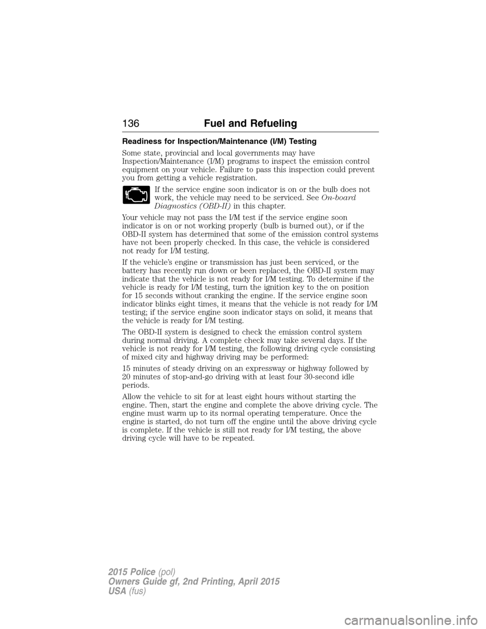
If the service engine soon indicator is on or the bulb does not
work, the vehicle may need to be serviced. SeeOn-board
Diagnostics (OBD-II)in this chapter.
Your vehicle may not pass the I/M test if the service engine soon
indicator is on or not working properly (bulb is burned out), or if the
OBD-II system has determined that some of the emission control systems
have not been properly checked. In this case, the vehicle is considered
not ready for I/M testing.
If the vehicle’s engine or transmission has just been serviced, or the
battery has recently run down or been replaced, the OBD-II system may
indicate that the vehicle is not ready for I/M testing. To determine if the
vehicle is ready for I/M testing, turn the ignition key to the on position
for 15 seconds without cranking the engine. If the service engine soon
indicator blinks eight times, it means that the vehicle is not ready for I/M
testing; if the service engine soon indicator stays on solid, it means that
the vehicle is ready for I/M testing.
The OBD-II system is designed to check the emission control system
during normal driving. A complete check may take several days. If the
vehicle is not ready for I/M testing, the following driving cycle consisting
of mixed city and highway driving may be performed:
15 minutes of steady driving on an expressway or highway followed by
20 minutes of stop-and-go driving with at least four 30-second idle
periods.
Allow the vehicle to sit for at least eight hours without starting the
engine. Then, start the engine and complete the above driving cycle. The
engine must warm up to its normal operating temperature. Once the
engine is started, do not turn off the engine until the above driving cycle
is complete. If the vehicle is still not ready for I/M testing, the above
driving cycle will have to be repeated.
136Fuel and Refueling
2015 Police(pol)
Owners Guide gf, 2nd Printing, April 2015
USA(fus)
Page 150 of 401
PRINCIPLES OF OPERATION
The traction control system helps avoid drive wheel spin and loss of
traction.
If your vehicle begins to slide, the system applies the brakes to individual
wheels and, when needed, reduces engine power at the same time. If the
wheels spin when accelerating on slippery or loose surfaces, the system
reduces engine power in order to increase traction.
USING TRACTION CONTROL
In certain situations (for example, stuck in snow or mud), turning the
traction control off may be beneficial as this allows the wheels to spin
with full engine power.
Turn the traction control system off through the information display. See
theInformation Displayschapter.
System indicator lights and messages
WARNING:If a failure has been detected within the
AdvanceTrac® system, the stability control light will illuminate
steadily. Verify that the AdvanceTrac® system was not manually
disabled using the information display control. If the stability control
light still illuminates steadily, have the system serviced by an authorized
dealer immediately. Operating your vehicle with AdvanceTrac® disabled
could lead to an increased risk of loss of vehicle control, vehicle
rollover, personal injury and death.
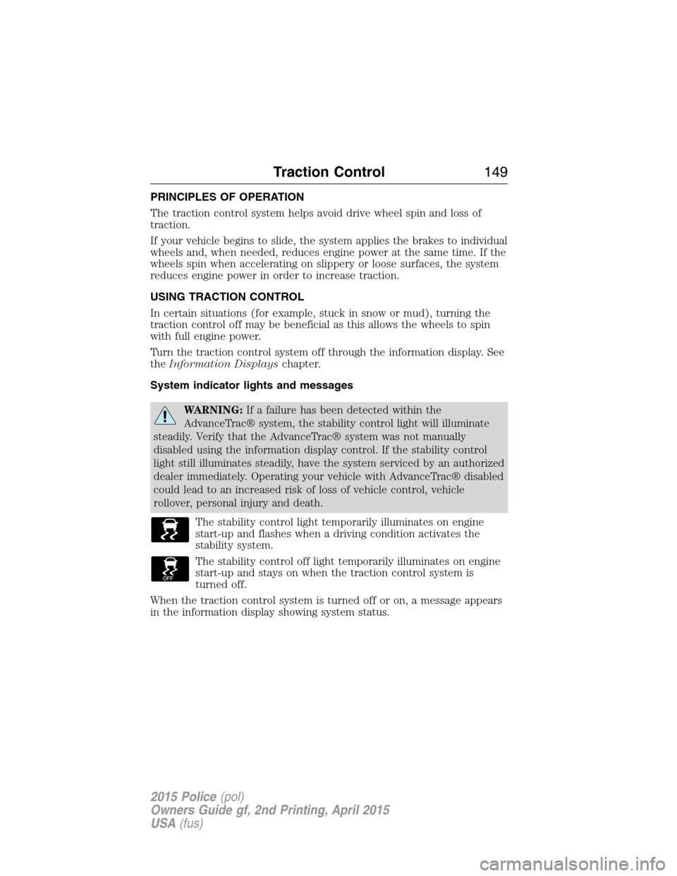
The stability control light temporarily illuminates on engine
start-up and flashes when a driving condition activates the
stability system.
The stability control off light temporarily illuminates on engine
start-up and stays on when the traction control system is
turned off.
When the traction control system is turned off or on, a message appears
in the information display showing system status.
Traction Control149
2015 Police(pol)
Owners Guide gf, 2nd Printing, April 2015
USA(fus)
Page 222 of 401
Engine fluid temperature management (EcoBoost engine only)
WARNING:To reduce the risk of collision and injury, be
prepared that the vehicle speed may reduce and the vehicle may
not be able to accelerate with full power until the fluid temperatures
reduce.
Your vehicle has been designed to pull a trailer, but because of the added
load, the vehicle’s engine may temporarily reach higher temperatures
during severe operating conditions such as ascending a long or steep
grade while pulling a trailer in hot ambient temperatures.
At this time, you may notice your engine coolant temperature gauge
needle move toward the H (hot) and the POWER REDUCED TO LOWER
TEMP message may appear on the message center.
You may notice a reduction in the vehicle’s speed caused by reduced
engine power. Your vehicle has been designed to enter this mode if
certain high temperature/high load conditions take place in order to
manage the engine’s fluid temperatures. The amount of speed reduction
will depend on the vehicle loading, towing, grade, ambient temperature,
and other factors. If this occurs, there is no need to pull off the road.
The vehicle can continue to be driven while this message is active.
The air conditioning may also cycle on and off during severe operating
conditions to protect overheating of the engine. When the engine coolant
temperature decreases to a more normal operating temperature, the air
conditioning will turn on once again.
If you notice any of the following:
•the engine coolant temperature gauge moves fully into the red (hot)
area
•the coolant temperature warning light illuminates
•the service engine soon indicator illuminates
1. Pull off the road as soon as safely possible and place the vehicle in P
(Park).
2. Leave the engine running until the coolant temperature gauge needle
moves away from the H range. After several minutes, if this does not
happen, follow the remaining steps.
3. Turn the engine off and wait for it to cool before checking the coolant
level.
Maintenance221
2015 Police(pol)
Owners Guide gf, 2nd Printing, April 2015
USA(fus)
Page 223 of 401
WARNING:Never remove the coolant reservoir cap while the
engine is running or hot.
4. If the coolant level is normal, you may restart your engine and
continue on.
5. If the coolant is low, add coolant, restart the engine and take your
vehicle to an authorized dealer. SeeAdding engine coolantin this
chapter for more information.
Refer to fail-safe cooling for additional information.
What you should know about fail-safe cooling
If the engine coolant supply is depleted, this feature allows the vehicle to
be driven temporarily before incremental component damage is incurred.
The “fail-safe” distance depends on ambient temperatures, vehicle load
and terrain.
How fail-safe cooling works
If the engine begins to overheat:
•The engine coolant temperature gauge will move to the red (hot)
area.
•The service engine soon indicator will illuminate.
If the engine reaches a preset over-temperature condition, the engine
will automatically switch to alternating cylinder operation. Each disabled
cylinder acts as an air pump and cools the engine.
When this occurs the vehicle will still operate. However:
•The engine power will be limited.
•The air conditioning system will be disabled.
Continued operation will increase the engine temperature and the engine
will completely shut down, causing steering and braking effort to
increase.
Once the engine temperature cools, the engine can be re-started. Take
your vehicle to an authorized dealer as soon as possible to minimize
engine damage.
222Maintenance
2015 Police(pol)
Owners Guide gf, 2nd Printing, April 2015
USA(fus)
Page 274 of 401
WARNING:To reduce the risk of serious injury, when mounting
replacement tires and wheels, you should not exceed the
maximum pressure indicated on the sidewall of the tire to set the beads
without additional precautions listed below. If the beads do not seat at
the maximum pressure indicated, re-lubricate and try again.
When inflating the tire for mounting pressures up to 20 psi (1.38 bar)
greater than the maximum pressure on the tire sidewall, the following
precautions must be taken to protect the person mounting the tire:
1. Make sure that you have the correct tire and wheel size.
2. Lubricate the tire bead and wheel bead seat area again.
3. Stand at a minimum of 12 feet (3.66 meters) away from the tire
wheel assembly.
4. Use both eye and ear protection.
For a mounting pressure more than 20 psi (1.38 bar) greater than the
maximum pressure, a Ford dealer or other tire service professional
should do the mounting.
Always inflate steel carcass tires with a remote air fill with the person
inflating standing at a minimum of 12 feet (3.66 meters) away from the
tire wheel assembly.
Your vehicle is equipped with tires designed to provide a safe ride and
handling capability.
Important:Remember to replace the wheel valve stems when the road
tires are replaced on your vehicle.
The two front tires or two rear tires should generally be replaced as a
pair.
The tire pressure sensors mounted in the wheels (originally installed on
your vehicle) are not designed to be used in aftermarket wheels.
The use of wheels or tires not recommended by Ford Motor Company
may affect the operation of your tire pressure monitoring system.
If the tire pressure monitoring system indicator is flashing, the system is
malfunctioning. Your replacement tire might be incompatible with your
tire pressure monitoring system, or some component of the system may
be damaged.
Wheels and Tires273
2015 Police(pol)
Owners Guide gf, 2nd Printing, April 2015
USA(fus)
Page 282 of 401
System sensor training procedure
Note:To reduce the chances of interference from another vehicle,
system training should be performed at least three feet (one meter)
away from another Ford Motor Company vehicle undergoing the system
training procedure at the same time.
Note:Do not wait more than two minutes between resetting each tire
sensor or the system will time-out and the entire procedure will have to
be repeated on all four wheels.
A double horn chirp indicates the need to repeat the procedure.
System training procedure
Note:It is recommended that you read the entire procedure before
attempting.
Note:To enter the training mode, Steps 1–6 must be completed within
60 seconds.
1. Place the ignition in the off position and keep the key in the ignition.
2. Press and release the brake pedal.
3. Cycle the ignition from off to on three times ending in the on position
- Do not start the engine.
4. Press and hold the brake pedal for two seconds, then release.
5. Turn the ignition to off - Do not remove the key.
6. Cycle the ignition from off to on three times ending in on - Do not
start the engine.
If the training mode has been entered successfully, the horn will sound
once, the system indicator will flash, and the information display will
show TRAIN LF TIRE.
If after repeated attempts to enter the training mode, the horn does not
sound, the system indicator does not flash, and the information display
does not show TRAIN LF TIRE, seek service from your authorized
dealer.
Wheels and Tires281
2015 Police(pol)
Owners Guide gf, 2nd Printing, April 2015
USA(fus)
Page 397 of 401

idle speed control ...................229
lubrication specifications .......296
refill capacities ........................296
service points ..................213, 215
Engine block heater .................124
Engine oil
checking and adding ..............217
dipstick ....................................217
filter, specifications ................302
refill capacities ........................296
specifications ..........................296
Event data recording ..................11
Exhaust fumes ..........................124
F
Fail safe cooling ........................222
Floor mats .................................185
Fluid capacities .........................296
Four-Wheel Drive vehicles
driving off road .......................141
Fuel
cap ...........................................130
capacity ...................................296
choosing the right fuel ...........127
filler funnel .............................128
filling your vehicle with fuel ..130
filter, specifications ........228, 302
fuel pump shut-off ..................188
octane rating ...........................128
quality ......................................127
running out of fuel .................128
safety information relating to
automotive fuels .....................126
Fuel and distance computer ....100
outside temperature
indicator ..................................100
to empty indicator ..................100
trip distance ............................100trip/reset button .....................100
Fuses ..........................................200
G
Gas cap (see Fuel cap) ............130
Gauges .........................................92
odometer .................................100
trip odometer ..........................100
H
Hazard flashers .........................188
Headlamps
aiming ......................................235
bulb specifications ..................245
flash to pass ..............................82
high beam .................................81
replacing bulbs .......................237
Head restraints .........................111
Heating ......................................107
Hood ..........................................211
I
Ignition .......................................121
Illuminated visor mirror .............91
Information displays ...................98
Inspection/maintenance (I/M)
testing ........................................136
Instrument panel
cleaning ...................................252
cluster ........................................93
J
Jack ............................................284
positioning ...............................284
storage .....................................284
396Index
2015 Police(pol)
Owners Guide gf, 2nd Printing, April 2015
USA(fus)