Page 196 of 441

Should your vehicle shut off after a
collision, you may restart your vehicle. For
vehicles equipped with a push button start
system:
1. Press the START/STOP button to
switch off the ignition.
2. Press the brake pedal (automatic transmission) or the clutch pedal
(manual transmission) and press the
START/STOP
button to start the
vehicle.
3. Remove your foot from the brake or clutch pedal and press the
START/STOP
button to switch off
the ignition.
4. Press the brake or clutch pedal and the
START/STOP
button, or switch on
the ignition only by pressing the
START/STOP
button without
pressing the brake or clutch pedal. Both
ways re-enable the fuel system.
Note: When you try to restart your vehicle
after a fuel shutoff, the vehicle makes sure
that various systems are safe to restart.
Once your vehicle determines that the
systems are safe, then the vehicle will allow
you to restart.
Note: In the event that your vehicle does
not restart after your third attempt, contact
an authorized dealer.
JUMP STARTING THE VEHICLE WARNINGS
The gases around the battery can
explode if exposed to flames, sparks,
or lit cigarettes. An explosion could
result in personal injury or vehicle damage. Batteries contain sulfuric acid which
can burn skin, eyes and clothing, if
contacted.
Use only an adequate-sized cable
with insulated clamps. Preparing Your Vehicle
Note:
Do not attempt to push-start your
automatic transmission vehicle. Automatic
transmissions do not have push-start
capability. Attempting to push-start a
vehicle with an automatic transmission may
cause transmission damage.
Note: Use only a 12-volt supply to start your
vehicle.
Note: Do not disconnect the battery of the
disabled vehicle as this could damage the
vehicle's electrical system.
Park the booster vehicle close to the hood
of the disabled vehicle, making sure the
two vehicles do not touch. Turn all
accessories off.
Connecting the Jumper Cables WARNING
Do not attach the cables to fuel lines,
engine rocker covers, the intake
manifold or electrical components
as grounding points. Stay clear of moving
parts. To avoid reverse polarity
connections, make sure that you correctly
identify the positive (+) and negative (-)
terminals on both the disabled and booster
vehicles before connecting the cables. Note:
In the illustration, the bottom vehicle
represents the booster vehicle.
193
Mustang (), enUSA, First Printing Roadside Emergencies
Page 206 of 441
Protected components
Fuse amp rating
Fuse or relay number
Automatic brake system pump.
50A*
5
Body control module.
50A*
6
Body control module.
60A*
7
Body control module.
50A*
8
Rear window defroster.
40A*
9
Blower motor.
40A*
10
Left-hand front window.
30A**
11
Driver seat.
30**
12
Passenger seat.
30A**
13
Climate-controlled seat module.
30A**
14
Convertible top motor.
20A**
15
Not used.
—
16
Convertible top motor.
20A**
17
Not used.
—
18
Steering column lock relay.
20A***
19
Brake on-off switch.
10A***
20
Horn.
20A***
21
Powertrain control module relay.
10A***
22
Air conditioning clutch.
10A***
23
Voltage quality module.
30A**
24
Not used.
—
25
Windshield wiper motor.
25A**
26
Not used.
—
27
Automatic brake system valve.
30A**
28
Electronic fan 1.
30A**
29
Starter motor solenoid.
30A**
30
Electronic fan 3.
40A**
31
203
Mustang (), enUSA, First Printing Fuses
Page 207 of 441
Protected components
Fuse amp rating
Fuse or relay number
Latch relay coil.
10A***
32
Left-hand high-intensity discharge head-
lamps.
20A***
33
Not used.
—
34
Right-hand high-intensity discharge head-
lamps.
20A
35
Alt sense.
10A***
36
Not used.
—
37
Vehicle power 1.
20A***
38
Not used.
—
39
Vehicle power 2.
20A***
40
Fuel injectors.
15A***
41
Vehicle power 3.
15A***
42
Not used.
—
43
Vehicle power 4.
15A***
44
Not used.
—
45
Not used.
—
46
Not used.
—
47
Not used.
—
48
Fuel pump.
30A**
49
Steering column lock relay.
—
50
Not used.
—
51
Horn relay.
—
52
Cigar lighter.
20A**
53
Auxiliary power point.
20A**
54
Electronic fan 2.
25A**
55
Not used.
—
56
Air conditioning clutch relay.
—
57
204
Mustang (), enUSA, First Printing Fuses
Page 214 of 441
2. Release the hood latch by pushing the
secondary release lever to your
left-hand side.
3. Lift the hood until the lift cylinders hold
it open.
4. To close, lower the hood. Make sure that the hood closes properly and fully
latches.
UNDER HOOD OVERVIEW - 2.3L ECOBOOST™ Battery (out of view). See Changing the 12V Battery (page 220).
A
Engine oil dipstick. See
Engine Oil Dipstick (page 214).
B
Engine oil filler cap. See
Engine Oil Check (page 214).
C
Brake fluid reservoir. See
Brake and Clutch Fluid Check (page 219).
D
211
Mustang (), enUSA, First Printing MaintenanceE174561 E174450
Page 215 of 441
Air filter assembly. See Changing the Engine Air Filter (page 227).
E
Engine coolant reservoir. See
Engine Coolant Check (page 215).
F
Windshield washer fluid reservoir. See
Washer Fluid Check (page 220).
G
Power distribution box. See
Fuses (page 202).
H
UNDER HOOD OVERVIEW - 3.7L Battery. See
Changing the 12V Battery (page 220).
A.
Engine oil filler cap. See
Engine Oil Check (page 214).
B.
Engine oil dipstick. See
Engine Oil Dipstick (page 214).
C.
Brake fluid reservoir. See
Brake and Clutch Fluid Check (page 219).
D.
Air filter assembly. See
Changing the Engine Air Filter (page 227).
E.
Engine coolant reservoir. See
Engine Coolant Check (page 215).
F.
Windshield washer fluid reservoir. See
Washer Fluid Check (page 220).
G.
Power distribution box. See
Fuses (page 202).
H.
212
Mustang (), enUSA, First Printing MaintenanceE174559
Page 216 of 441
UNDER HOOD OVERVIEW - 5.0L 32V TI-VCT
Battery (out of view). See Changing the 12V Battery (page 220).
A.
Engine oil filler cap. See
Engine Oil Check (page 214).
B.
Engine oil dipstick. See
Engine Oil Dipstick (page 214).
C.
Brake fluid reservoir. See
Brake and Clutch Fluid Check (page 219).
D.
Air filter assembly. See
Changing the Engine Air Filter (page 227).
E.
Engine coolant reservoir. See
Engine Coolant Check (page 215).
F.
Windshield washer fluid reservoir. See
Washer Fluid Check (page 220).
G.
Power distribution box. See
Fuses (page 202).
H.
213
Mustang (), enUSA, First Printing MaintenanceE174560
Page 222 of 441

5. If the coolant is low, add coolant, and
restart the engine. See Adding Engine
Coolant or How Fail-Safe Cooling
Works in this chapter for more
information.
MANUAL TRANSMISSION
FLUID CHECK
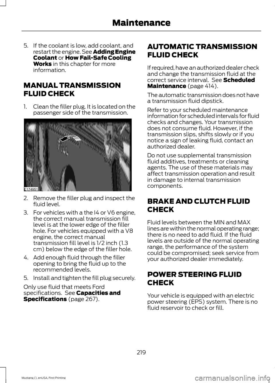
1. Clean the filler plug. It is located on the
passenger side of the transmission. 2. Remove the filler plug and inspect the
fluid level.
3. For vehicles with a the I4 or V6 engine,
the correct manual transmission fill
level is at the lower edge of the filler
hole. For vehicles equipped with a V8
engine, the correct manual
transmission fill level is 1/2 inch (1.3
cm) below the edge of the filler hole.
4. Add enough fluid through the filler opening to bring the fluid up to the
recommended levels.
5. Install and tighten the fill plug securely.
Only use fluid that meets Ford
specifications. See
Capacities and
Specifications (page 267). AUTOMATIC TRANSMISSION
FLUID CHECK
If required, have an authorized dealer check
and change the transmission fluid at the
correct service interval. See
Scheduled
Maintenance (page 414).
The automatic transmission does not have
a transmission fluid dipstick.
Refer to your scheduled maintenance
information for scheduled intervals for fluid
checks and changes. Your transmission
does not consume fluid. However, if the
transmission slips, shifts slowly or if you
notice a sign of leaking fluid, contact an
authorized dealer.
Do not use supplemental transmission
fluid additives, treatments or cleaning
agents. The use of these materials may
affect transmission operation and result
in damage to internal transmission
components.
BRAKE AND CLUTCH FLUID
CHECK
Fluid levels between the MIN and MAX
lines are within the normal operating range;
there is no need to add fluid. If the fluid
levels are outside of the normal operating
range, the performance of the system
could be compromised; seek service from
your authorized dealer immediately.
POWER STEERING FLUID
CHECK
Your vehicle is equipped with an electric
power steering (EPS) system. There is no
fluid reservoir to check or fill.
219
Mustang (), enUSA, First Printing MaintenanceE174951
Page 276 of 441

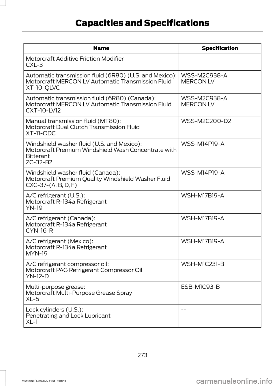
Specification
Name
Motorcraft Additive Friction Modifier
CXL-3 WSS-M2C938-A
Automatic transmission fluid (6R80) (U.S. and Mexico):
MERCON LV
Motorcraft MERCON LV Automatic Transmission Fluid
XT-10-QLVC
WSS-M2C938-A
Automatic transmission fluid (6R80) (Canada):
MERCON LV
Motorcraft MERCON LV Automatic Transmission Fluid
CXT-10-LV12
WSS-M2C200-D2
Manual transmission fluid (MT80):
Motorcraft Dual Clutch Transmission Fluid
XT-11-QDC
WSS-M14P19-A
Windshield washer fluid (U.S. and Mexico):
Motorcraft Premium Windshield Wash Concentrate with
Bitterant
ZC-32-B2
WSS-M14P19-A
Windshield washer fluid (Canada):
Motorcraft Premium Quality Windshield Washer Fluid
CXC-37-(A, B, D, F)
WSH-M17B19-A
A/C refrigerant (U.S.):
Motorcraft R-134a Refrigerant
YN-19
WSH-M17B19-A
A/C refrigerant (Canada):
Motorcraft R-134a Refrigerant
CYN-16-R
WSH-M17B19-A
A/C refrigerant (Mexico):
Motorcraft R-134a Refrigerant
MYN-19
WSH-M1C231-B
A/C refrigerant compressor oil:
Motorcraft PAG Refrigerant Compressor Oil
YN-12-D
ESB-M1C93-B
Multi-purpose grease:
Motorcraft Multi-Purpose Grease Spray
XL-5
--
Lock cylinders (U.S.):
Penetrating and Lock Lubricant
XL-1
273
Mustang (), enUSA, First Printing Capacities and Specifications