2015 FORD FOCUS ELECTRIC stop start
[x] Cancel search: stop startPage 127 of 369
GENERAL INFORMATION
Note:
Occasional brake noise is normal. If
a metal-to-metal, continuous grinding or
continuous squeal sound is present, the
brake linings may be worn-out. Have the
system checked by an authorized dealer. If
the vehicle has continuous vibration or
shudder in the steering wheel while braking,
have it checked by an authorized dealer.
Note: Brake dust may accumulate on the
wheels, even under normal driving
conditions. Some dust is inevitable as the
brakes wear and does not contribute to
brake noise. See Cleaning the Alloy
Wheels (page 186). See
Warning Lamps and
Indicators (page 83).
Wet brakes result in reduced braking
efficiency. Gently press the brake pedal a
few times when driving from a car wash or
standing water to dry the brakes.
Brake Over Accelerator
In the event the accelerator pedal
becomes stuck or entrapped, apply steady
and firm pressure to the brake pedal to
slow the vehicle and reduce engine power.
If you experience this condition, apply the
brakes and bring your vehicle to a safe
stop. Move the transmission to park (P),
switch the engine off and apply the parking
brake. Inspect the accelerator pedal for
any interference. If none are found and the
condition persists, have your vehicle towed
to the nearest authorized dealer.
Brake Assist
Brake assist detects when you brake
heavily by measuring the rate at which you
press the brake pedal. It provides
maximum braking efficiency as long as you
press the pedal. Brake assist can reduce
stopping distances in critical situations. Anti-lock Brake System
This system helps you maintain steering
control during emergency stops by keeping
the brakes from locking. This lamp momentarily
illuminates when you turn the
ignition on. If the light does not
illuminate during start up, remains on or
flashes, the system may be disabled. Have
the system checked by an authorized
dealer. If the anti-lock brake system is
disabled, normal braking is still effective. If the brake warning lamp
illuminates when you release the
parking brake, have the system
checked by an authorized dealer.
Regenerative Braking System
This feature is used to simulate the engine
braking of an internal combustion engine
and assist the standard brake system while
recovering some of the energy of motion
and storing it in the battery to improve the
range of your vehicle. The standard brake
system is designed to fully stop the car if
regenerative braking is not available.
During regenerative braking, the motor is
spun as a generator to create electrical
current. This recharges the battery and
slows the vehicle. In effect, once the
accelerator pedal is released, the motor
changes from an energy user to an energy
producer.
When the accelerator pedal is released or
the brake pedal is applied, the brake
controller automatically detects the
amount of deceleration requested and
optimizes how much of the deceleration
will be produced by regenerative braking.
The remaining portion is generated by
124
Focus (CDH), enUSA, First Printing BrakesE144522 E144522
Page 129 of 369
When the system is active, your vehicle will
remain stationary on the slope for two to
three seconds after you release the brake
pedal. This allows you time to move your
foot from the brake to the accelerator
pedal. The brakes are released
automatically once the engine has
developed sufficient drive to prevent your
vehicle from rolling down the slope. This
is an advantage when pulling away on a
slope, for example from a car park ramp,
traffic lights or when reversing uphill into
a parking space.
The system will activate automatically on
any slope that will cause significant vehicle
rollback. For vehicles with a manual
transmission, you can switch this feature
off using the information display. See
Information Displays (page 86). The
system will remain on or off depending on
how it was last set.
Note: The system only functions when you
bring your vehicle to a complete stop. Shift
into reverse (R) when facing downhill and
first gear (1) when facing uphill.
Note: There is no warning lamp to indicate
the system is either on or off.
Using Hill Start Assist
1. Press the brake pedal to bring your vehicle to a complete standstill. Keep
the brake pedal pressed.
2. If the sensors detect that your vehicle is on a slope, the system will activate
automatically.
3. When you remove your foot from the brake pedal, your vehicle will remain
on the slope without rolling away for
about two or three seconds. This hold
time will automatically be extended if
you are in the process of driving off.
4. Drive off in the normal manner. The brakes will release automatically.
126
Focus (CDH), enUSA, First Printing Brakes
Page 194 of 369
What to do When a Tire Is
Punctured
Repair a tire puncture within the tire's tread
area in two stages with the kit.
•
In the first stage, inflate the tire with a
sealing compound and air. After you
inflate the tire, you will need to drive
the vehicle a short distance (about 4
miles [6 kilometers]) to distribute the
sealant in the tire.
• In the second stage, check the tire
pressure and adjust, if necessary, to the
vehicle's specified tire inflation
pressure.
First Stage: Inflating the Tire with
Sealing Compound and Air WARNINGS
Do not stand directly over the kit
while inflating the tire. If you notice
any unusual bulges or deformations
in the tire's sidewall during inflation, stop
and call roadside assistance. If the tire does not inflate to the
recommended tire pressure within
15 minutes, stop and call roadside
assistance. Preparation: Park the vehicle in a safe, level
and secure area, away from moving traffic.
Switch the hazard lights on. Apply the
parking brake and switch the engine off.
Inspect the flat tire for visible damage.
WARNING
Do not run the engine during kit
operation unless the vehicle is
outdoors or in a well-ventilated area.
Sealant compound contains latex. To
avoid any allergic reactions, use the
non-latex gloves found in the accessory
box on the underside of the kit housing. Do not remove any foreign object that has
pierced the tire. If a puncture is located in
the tire sidewall, stop and call roadside
assistance.
1. Remove the valve cap from the tire
valve.
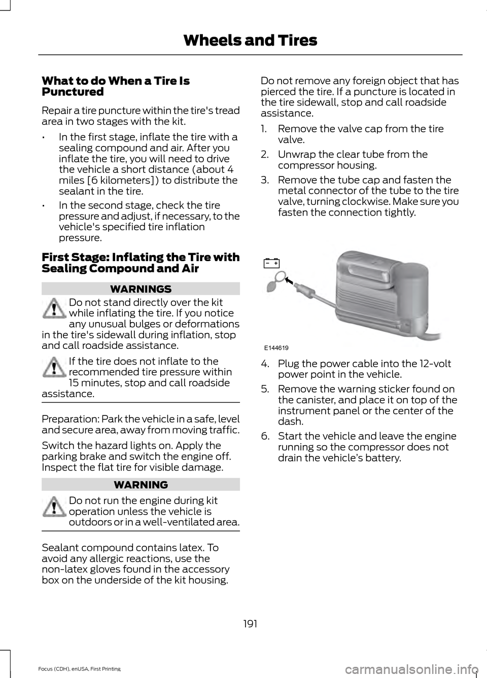
2. Unwrap the clear tube from the compressor housing.
3. Remove the tube cap and fasten the metal connector of the tube to the tire
valve, turning clockwise. Make sure you
fasten the connection tightly. 4. Plug the power cable into the 12-volt
power point in the vehicle.
5. Remove the warning sticker found on the canister, and place it on top of the
instrument panel or the center of the
dash.
6. Start the vehicle and leave the engine running so the compressor does not
drain the vehicle ’s battery.
191
Focus (CDH), enUSA, First Printing Wheels and TiresE144619
Page 200 of 369
Preparation: Park the vehicle in a safe, level
and secure area, away from moving traffic.
Switch the hazard lights on. Apply the
parking brake and switch the engine off.
Inspect the flat tire for visible damage.
Sealant compound contains latex. Use
appropriate precautions to avoid any
allergic reactions.
Do not remove any foreign object that has
pierced the tire. If a puncture is located in
the tire sidewall, stop and call roadside
assistance.
1. Remove the valve cap from the tire
valve.
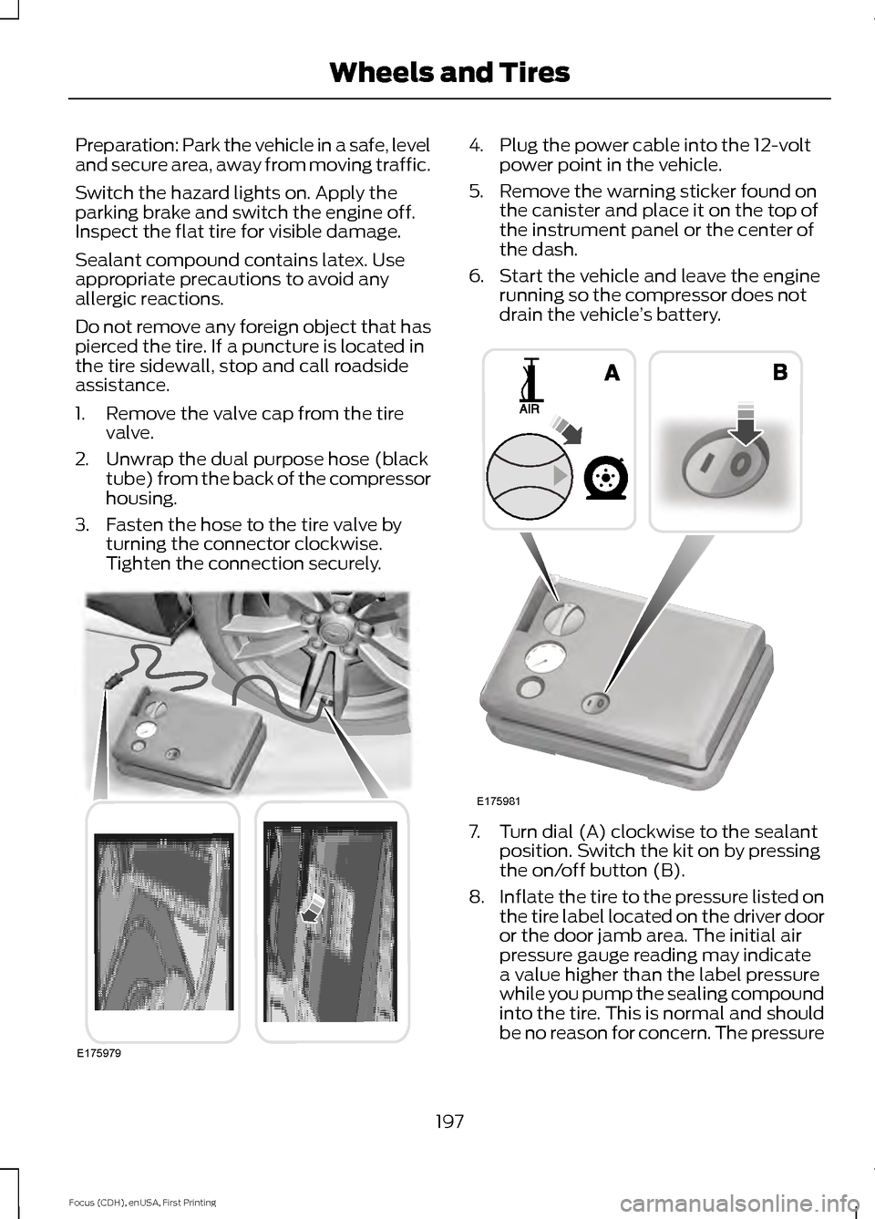
2. Unwrap the dual purpose hose (black tube) from the back of the compressor
housing.
3. Fasten the hose to the tire valve by turning the connector clockwise.
Tighten the connection securely. 4. Plug the power cable into the 12-volt
power point in the vehicle.
5. Remove the warning sticker found on the canister and place it on the top of
the instrument panel or the center of
the dash.
6. Start the vehicle and leave the engine running so the compressor does not
drain the vehicle ’s battery. 7. Turn dial (A) clockwise to the sealant
position. Switch the kit on by pressing
the on/off button (B).
8. Inflate the tire to the pressure listed on
the tire label located on the driver door
or the door jamb area. The initial air
pressure gauge reading may indicate
a value higher than the label pressure
while you pump the sealing compound
into the tire. This is normal and should
be no reason for concern. The pressure
197
Focus (CDH), enUSA, First Printing Wheels and TiresE175979 E175981
Page 217 of 369
It is recommended that the two
front tires or two rear tires
generally be replaced as a pair.
The tire pressure sensors mounted
in the wheels (originally installed
on your vehicle) are not designed
to be used in aftermarket wheels.
The use of wheels or tires not
recommended by Ford Motor
Company may affect the
operation of your tire pressure
monitoring system.
If the tire pressure monitoring
system indicator is flashing, your
tire pressure monitoring system is
malfunctioning. Your replacement
tire might be incompatible with
your TPMS, or some component
of the TPMS may be damaged.
Safety Practices
WARNINGS
If your vehicle is stuck in
snow, mud, sand, etc., do not
rapidly spin the tires. Spinning the
tires can tear the tire and cause
an explosion. A tire can explode in
as little as three to five seconds. Do not spin the wheels at
over 30 mph (56 km/h). The
tires may fail and injure a
passenger or bystander. Driving habits have a great deal
to do with your tire mileage and
safety.
Observe posted speed limits. Avoid fast starts, stops and turns.
Avoid potholes and objects on the
road.
Do not run over curbs or hit the tire
against a curb when parking.
Highway Hazards
No matter how carefully you drive
there is always the possibility that
you may eventually have a flat tire
on the highway. Drive slowly to the
closest safe area out of traffic.
This may further damage the flat
tire, but your safety is more
important.
If you feel a sudden vibration or
ride disturbance while driving, or
you suspect your tire or vehicle
has been damaged, immediately
reduce your speed. Drive with
caution until you can safely pull
off the road. Stop and inspect the
tires for damage. If a tire is
under-inflated or damaged,
deflate it, remove wheel and
replace it with your spare tire and
wheel. If you cannot detect a
cause, have the vehicle towed to
the nearest repair facility or tire
dealer to have the vehicle
inspected.
214
Focus (CDH), enUSA, First Printing Wheels and Tires
Page 367 of 369

Remote Control..............................................46
Changing the Remote Control Battery.........47
Intelligent Access Key........................................ 46
Locating Your Vehicle.......................................... 47
Programming a New Remote Control..........47
Remote Start......................................................... 48
Sounding the Panic Alarm............................... 48
Remote Start
.................................................103
Removing a Headlamp................................177
Repairing Minor Paint Damage...............186
Replacement Parts Recommendation.........................................9
Collision Repairs...................................................... 9
Scheduled Maintenance and Mechanical Repairs................................................................... 9
Warranty on Replacement Parts.................... 10
Replacing a Lost Key or Remote Control............................................................49
Reporting Safety Defects (Canada Only)...............................................................157
Reporting Safety Defects (U.S. Only)...............................................................156
Roadside Assistance
...................................147
Vehicles Sold in Canada: Getting Roadside
Assistance......................................................... 147
Vehicles Sold in Canada: Using Roadside Assistance......................................................... 147
Vehicles Sold in the United States: Getting Roadside Assistance..................................... 147
Vehicles Sold in the United States: Using Roadside Assistance..................................... 147
Roadside Emergencies...............................147
Running-In See: Breaking-In.................................................. 145
S
Safety Belt Height Adjustment.................32
Safety Belt Minder.........................................33 Belt-Minder™........................................................ 33
Safety Belts
......................................................29
Principle of Operation........................................ 29
Safety Belt Warning Lamp and Indicator Chime...............................................................33
Conditions of operation..................................... 33
Scheduled Maintenance Record............351
Scheduled Maintenance
...........................347
Seats.................................................................104 Security..............................................................64
Settings...........................................................240
Clock........................................................................\
241
Display.................................................................... 241
Settings................................................................. 246
Sound..................................................................... 243
Vehicle.................................................................... 243
Side Airbags
......................................................41
Side Curtain Airbags.....................................43
Sitting in the Correct Position
.................104
Snow Chains See: Using Snow Chains.................................. 216
Special Notices
................................................10
New Vehicle Limited Warranty........................ 10
On-board Diagnostics (OBD-II)...................... 10
Special Instructions............................................. 10
Speed Control See: Cruise Control............................................. 133
Stability Control............................................128 Principle of Operation....................................... 128
Starting and Stopping the Electric Motor...............................................................112
Starting the Electric Motor.........................112 Keyless Starting.................................................... 112
Starting Your Vehicle.......................................... 112
Steering............................................................134 Electric Power Steering.................................... 134
Steering Wheel
................................................67
Storage Compartments...............................111
Sun Visors.........................................................80
Illuminated Vanity Mirror.................................. 80
Supplementary Restraints System..........37 Principle of Operation......................................... 37
Switching Off the Electric Motor..............113
Symbols Glossary.............................................5
T
Tailgate See: Manual Liftgate............................................ 61
Technical Specifications See: Capacities and Specifications.............222
364
Focus (CDH), enUSA, First Printing Index