2015 FORD F250 steering wheel
[x] Cancel search: steering wheelPage 206 of 485
•
If your vehicle is equipped with
AdvanceTrac with RSC, this system
may turn on during typical cornering
maneuvers with a heavily loaded trailer.
This is normal. Turning the corner at a
slower speed while towing may reduce
this tendency.
• If you are towing a trailer frequently in
hot weather, hilly conditions, at the
gross combined weight rating (or any
combination of these factors), consider
refilling your rear axle with synthetic
gear lubricant (if the axle is not already
filled with it). See Capacities and
Specifications (page 301).
• Allow more distance for stopping with
a trailer attached. Anticipate stops and
brake gradually.
• Avoid parking on a grade. However, if
you must park on a grade:
1. Turn the steering wheel to point your vehicle tires away from traffic flow.
2. Set your vehicle parking brake.
3. Place the automatic transmission in position
P.
4. Place wheel chocks in front and back of the trailer wheels. (Chocks not
included with vehicle.)
Your vehicle may be equipped with a
temporary or conventional spare tire. A
"temporary" spare tire is different in size
(diameter or width), tread-type
(All-Season or All Terrain) or is from a
different manufacturer than the road tires
on your vehicle. Consult information on the
tire label or Safety Compliance label for
limitations when using.
Launching or Retrieving a Boat or
Personal Watercraft (PWC)
Note: Disconnect the wiring to the trailer
before
backing the trailer into the water.
Note: Reconnect the wiring to the trailer
after
you remove the trailer from the water. When backing down a ramp during boat
launching or retrieval:
•
Do not allow the static water level to
rise above the bottom edge of the rear
bumper.
• Do not allow waves to break higher
than 6 inches (15 centimeters) above
the bottom edge of the rear bumper.
Exceeding these limits may allow water to
enter vehicle components:
• Causing internal damage to the
components.
• Affecting driveability, emissions, and
reliability.
Replace the rear axle lubricant anytime
the rear axle has been submerged in water.
Water may have contaminated the rear
axle lubricant, which is not normally
checked or changed unless a leak is
suspected or other axle repair is required.
TOWING POINTS WARNINGS
Using recovery hooks is dangerous
and should only be done by a person
familiar with proper vehicle recovery
safety practices. Improper use of recovery
hooks may cause hook failure or separation
from the vehicle and could result in serious
injury or death. Always slowly remove the slack from
the recovery strap prior to pulling.
Failure to do so can introduce
significantly higher loads which can cause
the recovery hooks to break off, or the
recovery strap to fail which can cause
serious injury or death. Never link two straps together with
a clevis pin. These heavy metal
objects could become projectiles if
the strap breaks and can cause serious
injury or death. 203
Super Duty (), enUSA Towing
Page 211 of 485
•
Transmissions give their best fuel
economy when operated in the top
cruise gear and with steady pressure
on the gas pedal.
• Four-wheel-drive operation (if
equipped) is less fuel efficient than
two-wheel-drive operation.
• Close the windows for high-speed
driving.
DRIVING THROUGH WATER WARNING
Do not drive through flowing or deep
water as you may lose control of your
vehicle.
Note:
Driving through standing water can
cause vehicle damage.
Note: Engine damage can occur if water
enters the air filter.
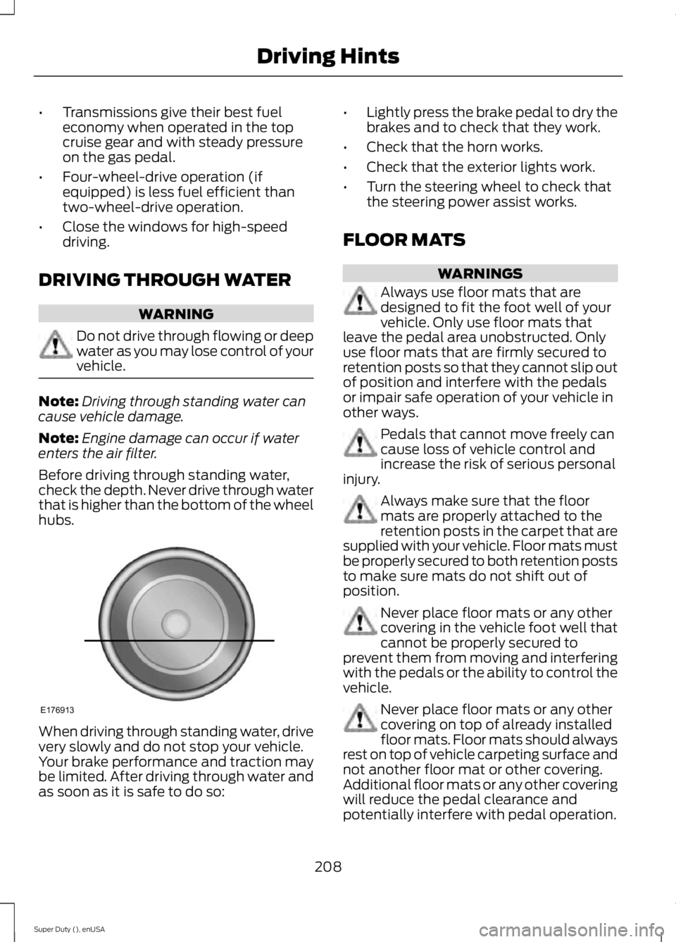
Before driving through standing water,
check the depth. Never drive through water
that is higher than the bottom of the wheel
hubs. When driving through standing water, drive
very slowly and do not stop your vehicle.
Your brake performance and traction may
be limited. After driving through water and
as soon as it is safe to do so: •
Lightly press the brake pedal to dry the
brakes and to check that they work.
• Check that the horn works.
• Check that the exterior lights work.
• Turn the steering wheel to check that
the steering power assist works.
FLOOR MATS WARNINGS
Always use floor mats that are
designed to fit the foot well of your
vehicle. Only use floor mats that
leave the pedal area unobstructed. Only
use floor mats that are firmly secured to
retention posts so that they cannot slip out
of position and interfere with the pedals
or impair safe operation of your vehicle in
other ways. Pedals that cannot move freely can
cause loss of vehicle control and
increase the risk of serious personal
injury. Always make sure that the floor
mats are properly attached to the
retention posts in the carpet that are
supplied with your vehicle. Floor mats must
be properly secured to both retention posts
to make sure mats do not shift out of
position. Never place floor mats or any other
covering in the vehicle foot well that
cannot be properly secured to
prevent them from moving and interfering
with the pedals or the ability to control the
vehicle. Never place floor mats or any other
covering on top of already installed
floor mats. Floor mats should always
rest on top of vehicle carpeting surface and
not another floor mat or other covering.
Additional floor mats or any other covering
will reduce the pedal clearance and
potentially interfere with pedal operation.
208
Super Duty (), enUSA Driving HintsE176913
Page 212 of 485
WARNINGS
Check attachment of floor mats on
a regular basis. Always properly
reinstall and secure floor mats that
have been removed for cleaning or
replacement. Always make sure that objects
cannot fall into the driver foot well
while the vehicle is moving. Objects
that are loose can become trapped under
the pedals causing a loss of vehicle control. Failure to properly follow floor mat
installation or attachment
instructions can potentially cause
interference with pedal operation causing
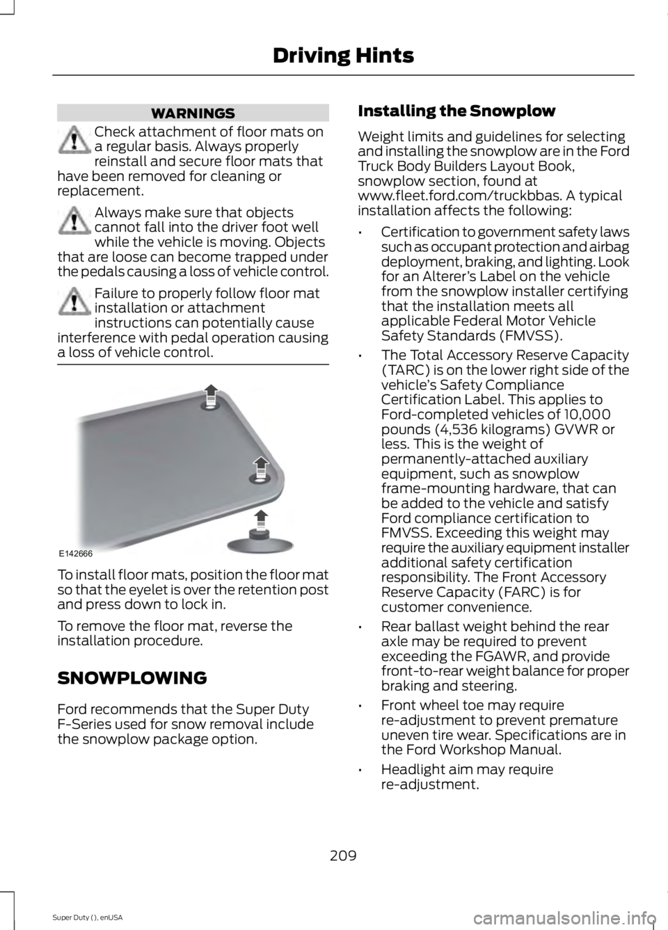
a loss of vehicle control. To install floor mats, position the floor mat
so that the eyelet is over the retention post
and press down to lock in.
To remove the floor mat, reverse the
installation procedure.
SNOWPLOWING
Ford recommends that the Super Duty
F-Series used for snow removal include
the snowplow package option. Installing the Snowplow
Weight limits and guidelines for selecting
and installing the snowplow are in the Ford
Truck Body Builders Layout Book,
snowplow section, found at
www.fleet.ford.com/truckbbas. A typical
installation affects the following:
•
Certification to government safety laws
such as occupant protection and airbag
deployment, braking, and lighting. Look
for an Alterer ’s Label on the vehicle
from the snowplow installer certifying
that the installation meets all
applicable Federal Motor Vehicle
Safety Standards (FMVSS).
• The Total Accessory Reserve Capacity
(TARC) is on the lower right side of the
vehicle ’s Safety Compliance
Certification Label. This applies to
Ford-completed vehicles of 10,000
pounds (4,536 kilograms) GVWR or
less. This is the weight of
permanently-attached auxiliary
equipment, such as snowplow
frame-mounting hardware, that can
be added to the vehicle and satisfy
Ford compliance certification to
FMVSS. Exceeding this weight may
require the auxiliary equipment installer
additional safety certification
responsibility. The Front Accessory
Reserve Capacity (FARC) is for
customer convenience.
• Rear ballast weight behind the rear
axle may be required to prevent
exceeding the FGAWR, and provide
front-to-rear weight balance for proper
braking and steering.
• Front wheel toe may require
re-adjustment to prevent premature
uneven tire wear. Specifications are in
the Ford Workshop Manual.
• Headlight aim may require
re-adjustment.
209
Super Duty (), enUSA Driving HintsE142666
Page 216 of 485
Canadian roadside coverage and benefits
may differ from the U.S. coverage. If you
require more information, please refer to
the coverage section of your warranty
guide, call us in Canada at
1-800-665-2006, or visit our website at
www.ford.ca.
Sykes Assistance Services Corporation
administers the Roadside Assistance
program. You must receive covered
services in Canada or the continental
United States. Coverage extends to
vehicles that use public, non-seasonal,
annually traveled roadways. Roadside
Assistance coverage does not extend to
vehicles involved in cross-country driving,
logging, autocross and any other form of
off-road use. Well maintained roads and
surfaces help ensure safe travel for the
supplier, and allow their representatives
to perform service as per the standard
operating procedures.
In Remote Locations
If our supplier cannot take your vehicle by
road to the nearest authorized dealership,
transportation by rail or water may be
necessary. The program covers a tow to
the dock or rail terminal and also to the
dealership at the end of the trip.
For rail or water transportation, however,
contact your authorized dealer to confirm
if you are eligible for additional coverage
before you authorize or pay for the service.
Call the Ford Roadside Assistance at
1-800-665-2006 for additional
information.
HAZARD WARNING FLASHERS
Note:
The hazard warning flashers will
operate when the ignition is in any position
or if the key is not in the ignition. If used
when the engine is not running, the battery
will lose charge. As a result, there may be
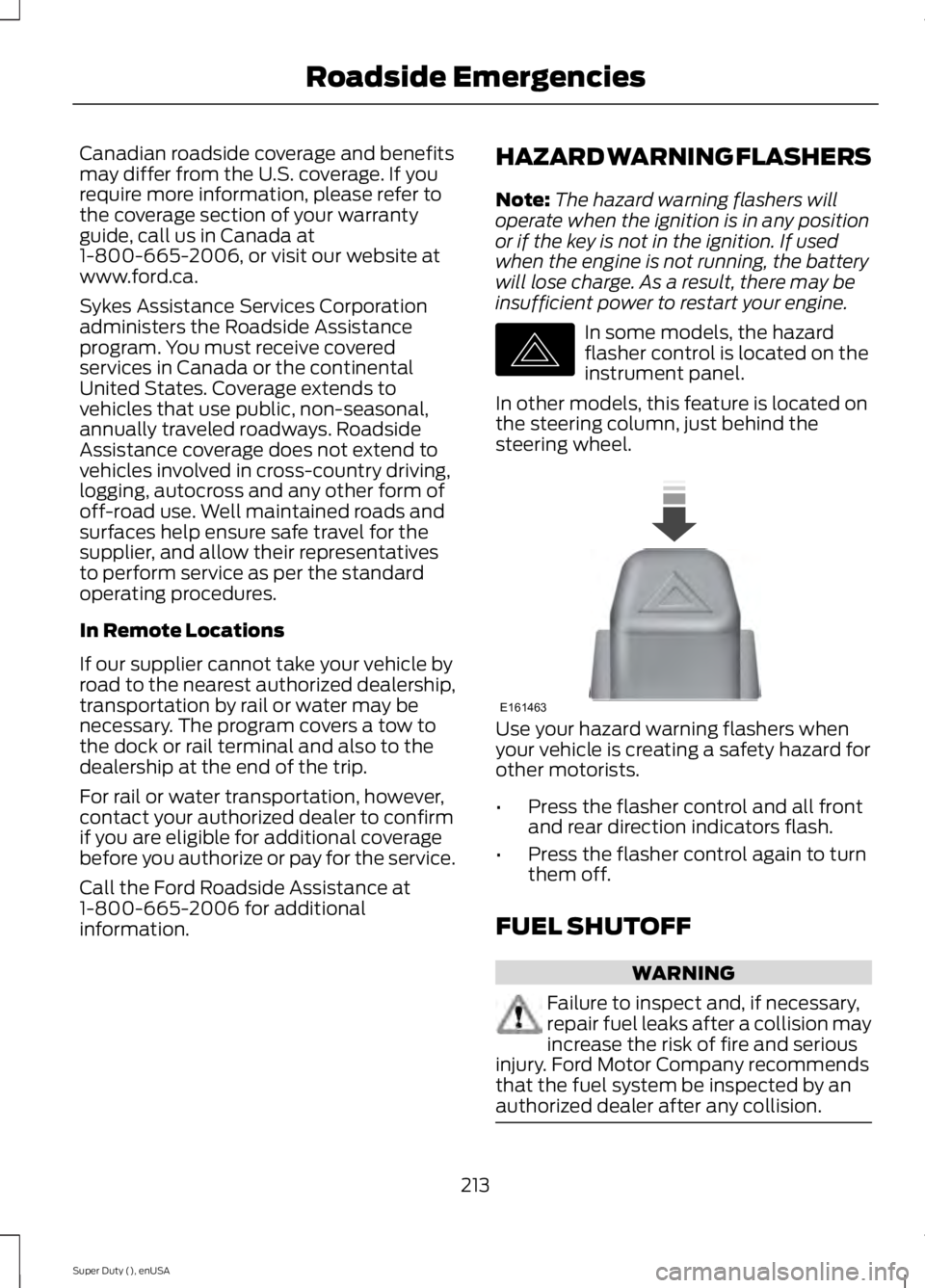
insufficient power to restart your engine. In some models, the hazard
flasher control is located on the
instrument panel.
In other models, this feature is located on
the steering column, just behind the
steering wheel. Use your hazard warning flashers when
your vehicle is creating a safety hazard for
other motorists.
•
Press the flasher control and all front
and rear direction indicators flash.
• Press the flasher control again to turn
them off.
FUEL SHUTOFF WARNING
Failure to inspect and, if necessary,
repair fuel leaks after a collision may
increase the risk of fire and serious
injury. Ford Motor Company recommends
that the fuel system be inspected by an
authorized dealer after any collision. 213
Super Duty (), enUSA Roadside EmergenciesE142663 E161463
Page 232 of 485

Protected components
Fuse amp rating
Fuse or relay number
Power mirror switch
10A
8
Auxiliary switch relay #3
10A
9
Customer access feed
10A
10
Run/accessory relay
Instrument cluster
10A
11
Interior lighting
15A
12
Lighted running board lamps
Right turn signals and brake lamps
15A
13
Left turn signals and brake lamps
15A
14
Backup lamps, Trailer tow backup relay
15A
15
High-mounted stop lamps
Reverse signal interior mirror
Right low beam headlamp
10A
16
Left low beam headlamp
10A
17
Brake shift interlock
10A
18
Keypad illumination
Passive anti-theft transceiver
Powertrain control module
Amplifier
20A
19
Subwoofer
Power door locks
20A
20
Brake on/off switch
10A
21
Horn
20A
22
Not used (spare)
15A
23
Diagnostic connector
15A
24
Electronic finish panel
Power fold mirror relay
Remote keyless entry
Steering wheel control module
Not used (spare)
15A
25
Steering wheel control module
5A
26
Not used (spare)
20A
27
229
Super Duty (), enUSA Fuses
Page 233 of 485

Protected components
Fuse amp rating
Fuse or relay number
Ignition switch
15A
28
GPS module
20A
29
Radio
SYNC
Parking lamp relay
15A
30
Trailer tow parking lamp relay
Customer access
5A
31
Trailer brake controller (brake signal)
Auto dimming mirror
15A
32
Driver and passenger door lock switch
illumination
Driver and passenger smart window motor
Moonroof motor
Passenger window switch
Power inverter
Rear heated seat switch illumination
Telescoping mirror switch
Restraint control module
10A
33
Heated steering wheel module
10A
34
Rear heated seats module
Reverse park aid module
5A
35
Select shift switch
Trailer brake control module
Fuel tank select switch
10A
36
Positive temperature coefficient heater
10A
37
AM/FM base radio
10A
38
High beam headlamps
15A
39
Parking lamps (in mirrors)
10A
40
Roof marker lamps
Passenger airbag deactivation indicator
7.5A
41
Not used (spare)
5A
42
Wiper relay
10A
43
Auxiliary switches
10A
44
230
Super Duty (), enUSA Fuses
Page 246 of 485
3.
Add only enough fluid through the filler
opening so that the fluid level is at the
bottom of the opening.
Only use fluid that meets Ford
specifications. See Capacities and
Specifications (page 301).
BRAKE FLUID CHECK
Fluid levels between the
MIN and MAX
lines are within the normal operating range;
there is no need to add fluid. If the fluid
levels are outside of the normal operating
range, the performance of the system
could be compromised; seek service from
your authorized dealer immediately.
POWER STEERING FLUID
CHECK
Check the power steering fluid. See
Scheduled Maintenance
(page 457). If
adding fluid is necessary, use only
MERCON LV ATF
Note: This procedure is for vehicles with
gasoline engines. Vehicles with diesel
engines are similar. See Under Hood
Overview in your diesel supplement.
Check the fluid level when it is at ambient
temperature.
1. Check the fluid level in the reservoir. It should be between the MIN and MAX
range. Do not add fluid if the level is
within this range.
2. If the fluid level is low, add fluid to bring
the fluid level up to between the MIN
and MAX range.
3. Switch the engine on.
4. While the engine idles, turn the steering
wheel left and right several times.
5. Switch the engine off. 6. Recheck the fluid level in the reservoir.
Do not add fluid if the level is between
the MIN and MAX range.
7. If the fluid is low, add fluid in small amounts, continuously checking the
level until it is between the MIN and
MAX range. For proper fluid type, See
Capacities and Specifications (page
301). Be sure to put the cap back on the
reservoir.
WASHER FLUID CHECK WARNING
If you operate your vehicle in
temperatures below 40°F (5°C), use
washer fluid with antifreeze
protection. Failure to use washer fluid with
antifreeze protection in cold weather could
result in impaired windshield vision and
increase the risk of injury or accident. Add fluid to fill the reservoir if the level is
low. Only use a washer fluid that meets
Ford specifications. See
Capacities and
Specifications (page 301).
State or local regulations on volatile
organic compounds may restrict the use
of methanol, a common windshield washer
antifreeze additive. Washer fluids
containing non-methanol antifreeze
agents should be used only if they provide
cold weather protection without damaging
the vehicle ’s paint finish, wiper blades or
washer system.
FUEL FILTER
Your vehicle is equipped with a lifetime
fuel filter that is integrated with the fuel
tank. Regular maintenance or replacement
is not needed.
243
Super Duty (), enUSA Maintenance
Page 248 of 485
6. Release the parking brake. With your
foot on the brake pedal and with the
A/C on, put the vehicle in D and allow
the engine to idle for at least one
minute.
• If you do not allow the engine to
relearn its idle trim, the idle quality
of your vehicle may be adversely
affected until the idle trim is
eventually relearned.
7. Drive the vehicle to complete the relearning process
•The vehicle may need to be driven
10 mi (16 km) or more to relearn the
idle and fuel trim strategy along
with the ethanol content for flexible
fuel vehicles.
• For flexible fuel vehicles, if you are
operating on E85, you may
experience poor starts or an
inability to start the engine and
driveability problems until the fuel
trim and ethanol content have been
relearned.
If the battery has been disconnected or a
new battery has been installed, the clock
and radio settings must be reset once the
battery is reconnected.
Always dispose of automotive
batteries in a responsible manner.
Follow your local authorized standards
for disposal. Call your local authorized
recycling center to find out more about
recycling automotive batteries.
Battery Management System (If
Equipped)
The battery management system (BMS)
monitors battery conditions and takes
actions to extend battery life. If excessive
battery drain is detected, the system may
temporarily disable certain electrical
features to protect the battery. Those
electrical accessories affected include the
rear defrost, heated/cooled seats, climate control fan, heated steering wheel, audio
and navigation system. A message may be
shown in the information displays to alert
the driver that battery protection actions
are active. These messages are only for
notification that an action is taking place,
and not intended to indicate an electrical
problem or that the battery requires
replacement.
Electrical accessory installation
To ensure proper operation of the BMS,
any electrical devices that are added to
the vehicle should not have their ground
connection made directly at the negative
battery post. A connection at the negative
battery post can cause inaccurate
measurements of the battery condition
and potential incorrect system operation.
Note:
Electrical or electronic accessories
added to the vehicle by the dealer or the
owner may adversely affect battery
performance and durability, and may also
affect the performance of other electrical
systems in the vehicle.
When a battery replacement is required,
the battery should only be replaced with
a Ford recommended replacement battery
which matches the electrical requirements
of the vehicle. After battery replacement,
or in some cases after charging the battery
with the external charger, the BMS requires
eight hours of vehicle sleep time (key off
with doors closed) to relearn the new
battery state of charge. Prior to relearning
the state of charge, the BMS may disable
electrical features (to protect the battery)
earlier than normal.
245
Super Duty (), enUSA Maintenance