2015 FIAT GRANDE PUNTO ACTUAL instrument panel
[x] Cancel search: instrument panelPage 5 of 216

4
SAFETY
STARTING
AND DRIVING
WARNING
LIGHTS AND
MESSAGES
IN AN
EMERGENCY
SERVICE
AND CARE
TECHNICAL
SPECIFICATIONS
INDEX
CONTROLS
AND DEVICESDASHBOARD ...................................................................... 5
SYMBOLS ............................................................................... 6
THE FIAT CODE SYSTEM ................................................. 6
THE KEYS .............................................................................. 8
ALARM ................................................................................... 10
IGNITION ............................................................................. 12
INSTRUMENT PANEL ........................................................ 13
INSTRUMENTS .................................................................... 14
DIGITAL DISPLAY ............................................................... 16
MULTIFUNCTION DISPLAY ............................................ 21
TRIP COMPUTER ................................................................ 30
FRONT SEATS ..................................................................... 32
REAR SEATS .......................................................................... 33
HEAD RESTRAINTS ........................................................... 34
STEERING WHEEL .............................................................. 35
MIRRORS ............................................................................... 35
HEATING AND VENTILATION SYSTEM .................... 37
MANUAL CLIMATE CONTROL SYSTEM .................... 41
EXTERIOR LIGHTS ............................................................. 47
WINDOW CLEANING ..................................................... 49
CEILING COURTESY LIGHTS ......................................... 51
CONTROLS ........................................................................ 53
FUEL CUT-OFF SYSTEM ................................................... 55INTERIOR FITTINGS........................................................... 56
SKYDOME SUNROOF ....................................................... 60
DOORS .................................................................................. 62
ELECTRIC WINDOW OPENING ................................. 65
BOOT ..................................................................................... 67
BONNET ............................................................................... 70
ROOF RACK/SKI RACK .................................................... 71
HEADLIGHTS ....................................................................... 72
ABS SYSTEM ......................................................................... 74
ESP SYSTEM .......................................................................... 75
EOBD SYSTEM ..................................................................... 78
“DUAL DRIVE” ELECTRIC POWER
STEERING SYSTEM ............................................................. 79
START&STOP SYSTEM ...................................................... 81
SYSTÈME GEAR SHIFT INDICATOR ............................. 86
SOUND SYSTEM ................................................................. 87
ABILITY TO INSTALL A PORTABLE
NAVIGATION SYSTEM ..................................................... 88
ACCESSORIES PURCHASED BY THE OWNER ......... 88
REFEULLING THE CAR ..................................................... 90
PROTECTING THE ENVIRONMENT ........................... 91
C C
O O
N N
T T
R R
O O
L L
S S
A A
N N
D D
D D
E E
V V
I I
C C
E E
S S
001-032 ACTUAL 1ed EN.qxd 31-08-2010 9:24 Pagina 4
Page 6 of 216

DASHBOARD
The presence and position of the controls, the instruments and the indicators may vary according to the versions.
1.Adjustable side air vents – 2.Fixed side air vents – 3.Left-hand lever: exterior lights control – 4.Instrument panel – 5.Right-
hand lever: front and rear windscreen wiper controls, trip computer – 6.Controls on dashboard – 7.Adjustable central air vents
– 8.Fixed upper air vent – 9.Front airbag, passenger side – 10.Glove compartment – 11.Sound system (for versions/markets
where provided) – 12.HVAC controls – 13.Ignition – 14.Front airbag, driver’s side – 15. Steering wheel adjustment lever
– 16.Controls display: fog light/rear fog lamp/headlamp alignment adjustment/digital display/multifunction display.
5
SAFETY
STARTING
AND DRIVING
WARNING
LIGHTS AND
MESSAGES
IN AN
EMERGENCY
SERVICE
AND CARE
TECHNICAL
SPECIFICATIONS
INDEX
CONTROLS
AND DEVICES
F0M0400mfig. 1
001-032 ACTUAL 1ed EN.qxd 31-08-2010 9:24 Pagina 5
Page 14 of 216

13
SAFETY
STARTING
AND DRIVING
WARNING
LIGHTS AND
MESSAGES
IN AN
EMERGENCY
SERVICE
AND CARE
TECHNICAL
SPECIFICATIONS
INDEX
CONTROLS
AND DEVICES
INSTRUMENT PANEL
Versions with digital display
ASpeedometer
BFuel level gauge with reserve warning
light
CEngine coolant temperature gauge and
excessive temperature warning light
DRev counter
EDigital display
Versions with multifunction display
ASpeedometer
BFuel level gauge with reserve warning
light
CEngine coolant temperature gauge and
excessive temperature warning light
DRev counter
EMultifunction display
F0M0535m
fig. 10
F0M0536mfig. 11
001-032 ACTUAL 1ed EN.qxd 31-08-2010 9:24 Pagina 13
Page 48 of 216

47
SAFETY
STARTING
AND DRIVING
WARNING
LIGHTS AND
MESSAGES
IN AN
EMERGENCY
SERVICE
AND CARE
TECHNICAL
SPECIFICATIONS
INDEX
CONTROLS
AND DEVICES
EXTERIOR LIGHTS
The left-hand stalk fig. 39operates most
of the external lights.
The external lights can be switched on on-
ly when the key is turned to MAR.
The instrument panel and the various con-
trols on the dashboard will be lit up when
the exterior lights are switched on.
LIGHTS OFF
Twist switch turned to position O.
SIDELIGHTS – TAIL LIGHTS
Twist the switch to position
6.
The light
3on the instrument panel
comes on.FLASHING THE HEADLIGHTS
Pull the stalk towards the steering wheel
(1
atemporary position) regardless of the
position of the twist switch. The warn-
ing light
1on the instrument panel will
come on.
fig. 39F0M0060m
DIPPED BEAM HEADLIGHTS
Twist the switch to position
2.
The light
3on the instrument panel
comes on.
MAIN BEAM HEADLIGHTS
When the twist switch is at
2, pull the
stalk towards the steering wheel (2ndtem-
porary position).
The warning light
1on the instrument
panel will come on.
To turn the main beams off, pull the stalk
towards the steering wheel again (dipped
beams will come back on).
033-071 ACTUAL 1ed EN 18-01-2011 11:49 Pagina 47
Page 49 of 216

48
SAFETY
STARTING
AND DRIVING
WARNING
LIGHTS AND
MESSAGES
IN AN
EMERGENCY
SERVICE
AND CARE
TECHNICAL
SPECIFICATIONS
INDEX
CONTROLS
AND DEVICES
DIRECTION INDICATORS fig. 40
Put the stalk in the permanent position:
❒Up (position 1): right-hand direction in-
dicator;
❒Down (position 2): left-hand direction
indicator.
The
¥or Îlights will blink on the in-
strument panel.
Indicators are switched off automatically
when the steering wheel is straightened.
If you want the indicator to flash briefly to
show that you are about to change lane,
move the stalk up or down without it
clicking into position. When released, the
stalk will return to its default position.
Lane change function
If you wish to signal a lane change, put the
left stalk in the temporary position for less
than half a second. The direction indicator
on the side selected will be activated for
5 flashes and then go out automatically.“FOLLOW ME HOME” DEVICE
This will light up the space in front of the
vehicle for a certain period of time.
Activation
With the key turned to STOPor re-
moved, pull the left-hand stalk towards the
steering wheel within 2 minutes from
when the engine is turned off.
Each time the stalk is moved, the lights
stay on for an extra 30 seconds up to
a maximum of 210 seconds; then the lights
are switched off automatically.When the stalk is moved, the light
3on
the instrument panel will light up and the
corresponding message will appear in the
display (see “Warning lights and mes-
sages”) as long as the function is on. The
light comes on when the stalk is first
moved and stays on until the function is
automatically deactivated. Each movement
of the stalk increases only the amount of
time the lights stay on.
Deactivation
Keep the stalk pulled towards the steer-
ing wheel for more than 2 seconds.
fig. 40F0M0061m
033-071 ACTUAL 1ed EN 21-07-2010 14:25 Pagina 48
Page 54 of 216

53
SAFETY
STARTING
AND DRIVING
WARNING
LIGHTS AND
MESSAGES
IN AN
EMERGENCY
SERVICE
AND CARE
TECHNICAL
SPECIFICATIONS
INDEX
CONTROLS
AND DEVICES
CONTROLS
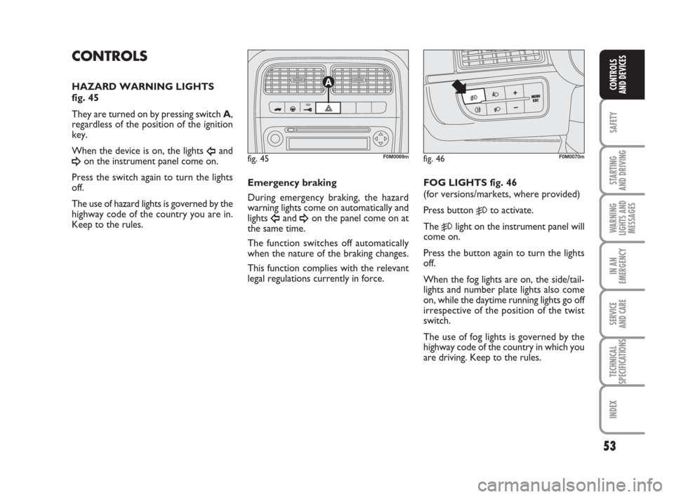
HAZARD WARNING LIGHTS
fig. 45
They are turned on by pressing switch A,
regardless of the position of the ignition
key.
When the device is on, the lights
Îand
¥on the instrument panel come on.
Press the switch again to turn the lights
off.
The use of hazard lights is governed by the
highway code of the country you are in.
Keep to the rules.Emergency braking
During emergency braking, the hazard
warning lights come on automatically and
lights
Îand ¥on the panel come on at
the same time.
The function switches off automatically
when the nature of the braking changes.
This function complies with the relevant
legal regulations currently in force.FOG LIGHTS fig. 46
(for versions/markets, where provided)
Press button 5to activate.
The
5light on the instrument panel will
come on.
Press the button again to turn the lights
off.
When the fog lights are on, the side/tail -
lights and number plate lights also come
on, while the daytime running lights go off
irrespective of the position of the twist
switch.
The use of fog lights is governed by the
highway code of the country in which you
are driving. Keep to the rules.
fig. 45F0M0069mfig. 46F0M0070m
033-071 ACTUAL 1ed EN 21-07-2010 14:25 Pagina 53
Page 55 of 216

54
SAFETY
STARTING
AND DRIVING
WARNING
LIGHTS AND
MESSAGES
IN AN
EMERGENCY
SERVICE
AND CARE
TECHNICAL
SPECIFICATIONS
INDEX
CONTROLS
AND DEVICES
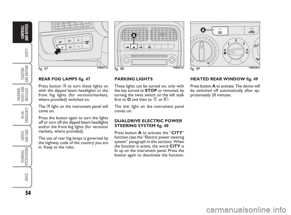
HEATED REAR WINDOW fig. 49
Press button Ato activate. The device will
be switched off automatically after ap-
proximately 20 minutes.
fig. 49F0M0036m
PARKING LIGHTS
These lights can be turned on, only with
the key turned to STOPor removed, by
turning the twist switch on the left stalk
first to Oand then to
6or 2.
The
3light on the instrument panel
comes on.
DUALDRIVE ELECTRIC POWER
STEERING SYSTEM fig. 48
Press button A to activate the “CITY”
function (see the “Electric power steering
system” paragraph in this section). When
the function is active, the word CITYis
lit up on the instrument panel. Press the
button again to deactivate the function.
fig. 48F0M0073m
REAR FOG LAMPS fig. 47
Press button 4to turn these lights on
with the dipped beam headlights or the
front fog lights (for versions/markets,
where provided) switched on.
The 4light on the instrument panel will
come on.
Press the button again to turn the lights
off or turn off the dipped beam headlights
and/or the front fog lights (for versions/
markets, where provided).
The use of rear fog lamps is governed by
the highway code of the country you are
in. Keep to the rules.
fig. 47F0M0071m
033-071 ACTUAL 1ed EN 21-07-2010 14:25 Pagina 54
Page 73 of 216

72
SAFETY
STARTING
AND DRIVING
WARNING
LIGHTS AND
MESSAGES
IN AN
EMERGENCY
SERVICE
AND CARE
TECHNICAL
SPECIFICATIONS
INDEX
CONTROLS
AND DEVICES
HEADLIGHTS
LIGHT BEAM DIRECTION
The correct direction of the headlights is
essential for the comfort and safety of the
driver and other road users. The head-
lights must be correctly directed to ensure
the best visibility. Contact a Fiat Dealer-
ship to have the direction checked and, if
necessary, adjusted.
HEADLIGHT ALIGNMENT
CORRECTOR
This device works with the key atMAR
and the dipped beam headlights on. The
car will slant backwards when it is loaded,
raising the light beam. The beams must
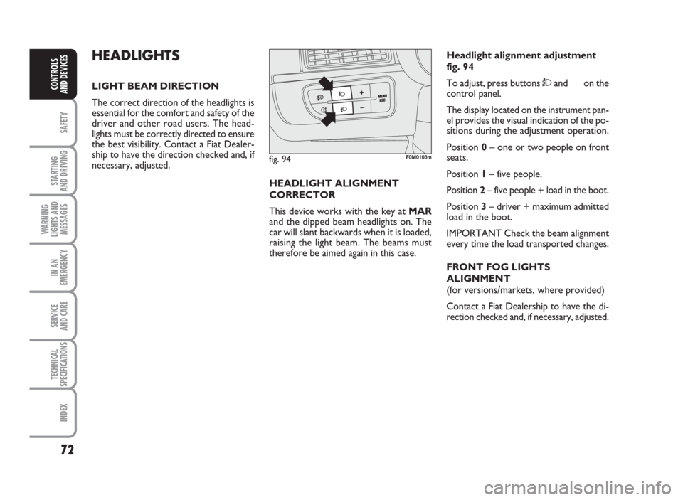
therefore be aimed again in this case.Headlight alignment adjustment
fig. 94
To adjust, press buttonsÒand on the
control panel.
The display located on the instrument pan-
el provides the visual indication of the po-
sitions during the adjustment operation.
Position0– one or two people on front
seats.
Position1– five people.
Position2– five people + load in the boot.
Position3– driver + maximum admitted
load in the boot.
IMPORTANT Check the beam alignment
every time the load transported changes.
FRONT FOG LIGHTS
ALIGNMENT
(for versions/markets, where provided)
Contact a Fiat Dealership to have the di-
rection checked and, if necessary, adjusted.
fig. 94F0M0103m
072-092 ACTUAL 1ed EN 26-07-2010 10:54 Pagina 72