2015 FIAT FREEMONT interior lights
[x] Cancel search: interior lightsPage 216 of 412

The SABICs and SABs (“Side Air Bags”) are designed to
activate in certain side impacts and certain rollover
events. The Occupant Restraint Controller (“ORC”)
determines whether the deployment of the Side Air
Bags in a particular side impact or rollover event is
appropriate, based on the severity and type of collision.
Vehicle damage by itself is not a good indicator of
whether or not Side Air Bags should have deployed.
Side Air Bags are a supplement to the seat belt restraint
system. Side Air Bags deploy in less time than it takes to
blink your eyes. Occupants, including children, who are
up against or very close to Side Air Bags can be
seriously injured or killed. Occupants, including chil-
dren, should never lean on or sleep against the door,
side windows, or area where the Side Air Bags inflate,
even if they are in an infant or child restraint.
Seat belts (and child restraints where appropriate) are
necessary for your protection in all collisions. They also
help keep you in position, away from inflating Side Air
Bags. To get the best protection from the Side Air Bags,
occupants must wear their seat belts properly and sit
upright with their backs against the seats. Children
must be properly restrained in a child restraint or
booster seat that is appropriate for the size of the child.WARNING!
• Side Air Bags need room to inflate. Do
n ot
lean against the door or window. Sit
upright in the center of the seat .
• Being too close to the Side Air Bags during
deployment could cause you to be severely in-
jured or killed.
• Relying on the Side Air Bags alone could lead to
more severe injuries in a collision. The Side Air
Bags work with your seat belt to restrain you
properly. In some collisions, Side Air Bags won’t
deploy at all. Always wear your seat belt even
though you have Side Air Bags.
NOTE: Air bag covers may not be obvious in the
interior trim, but they will open during air bag deploy-
ment.
Side Impacts
In side impacts, the side impact sensors aid the ORC in
determining the appropriate response to impact
events. The system is calibrated to deploy the Side Air
Bags on the impact side of the vehicle during impacts
that require Side Air Bag occupant protection. In side
impacts, the Side Air Bags deploy independently; a left
side impact deploys the left Side Air Bags only and a
right side impact deploys the right Side Air Bags only.
210
KNOWING YOUR
VEHICLE
SAFETY
STARTING AND
DRIVING
WARNING LIGHTSAND
MESSAGES
IN
AN
EMERGENCY
SERVICINGAND CARE
TECHNICAL
SPECIFICATIONS
CONTENTS
Page 218 of 412

Do not drive your vehicle after the air bags have
deployed. If you are involved in another collision, the
air bags will not be in place to protect you.
WARNING!
Deployed air bags and seat belt preten-
sion er
s cannot protect you in another
collision. Have the air bags, seat belt pretension-
ers, and the seat belt retractor assemblies re-
placed by an authorized dealer immediately.
Also, have the Occupant Restraint Controller Sys-
tem serviced as well.
NOTE:
• Air bag covers may not be obvious in the interior trim, but they will open during air bag deployment.
• After any collision, the vehicle should be taken to an authorized dealer immediately. ENHANCED ACCIDENT RESPONSE
SYSTEM
In the event of an impact, if the communication net-
work remains intact, and the power remains intact,
depending on the nature of the event, the ORC will
determine whether to have the Enhanced Accident
Response System perform the following functions:
• Cut off fuel to the engine.
• Flash hazard lights as long as the battery has power
or until the ignition switch is turned to the “OFF”
position.
• Turn on the interior lights, which remain on as long as the battery has power or until the ignition switch
is turned to the “OFF” position.
• Unlock the doors automatically.
SYSTEM RESET PROCEDURE
In order to reset the Enhanced Accident Response
System functions after an event, the ignition switch
must be changed from ignition START or ON/RUN to
ignition OFF.
212
KNOWING YOUR
VEHICLE
SAFETY
STARTING AND
DRIVING
WARNING LIGHTSAND
MESSAGES
IN
AN
EMERGENCY
SERVICINGAND CARE
TECHNICAL
SPECIFICATIONS
CONTENTS
Page 239 of 412

WARNING!
• An incorrectly anchored tether strap
c ould
lead to increased head motion and
possible injury to the child. Use only the anchor-
age position directly behind the child seat to
secure a child restraint top tether strap.
• If your vehicle is equipped with a split rear
seat , make sure the tether strap does not slip into
the opening between the seatbacks as you re-
move slack in the strap.
WARNING!
The child restraint owner ’s manual pro-
vides ins
tructions for installing the child
restraint using the seat belt . Read and follow
these instructions to install the child seat
properly.
Transporting Pets
Air Bags deploying in the front seat could harm your
pet. An unrestrained pet could be thrown about and
possibly injured, or injure a passenger during panic
braking or in a collision.
Pets should be restrained in the rear seat in pet har-
nesses or pet carriers that are secured by seat belts.
SAFETY TIPS
Transporting Passengers
NEVER TRANSPORT PASSENGERS IN THE CARGO
AREA.
WARNING!
• Do not leave children or animals inside
par k
ed vehicles in hot weather. Interior
heat build-up may cause serious injury or death.
• It is extremely dangerous to ride in a cargo
area, inside or outside of a vehicle. In a collision,
people riding in these areas are more likely to be
seriously injured or killed.
• Do not allow people to ride in any area of your
vehicle that is not equipped with seats and seat
belts.
• Be sure everyone in your vehicle is in a seat and
using a seat belt properly.
• On seven passenger models, do not drive the
vehicle with the second row passenger seat in the
easy entry/exit position (seat cushion flipped up-
ward and seat moved forward), as this position is
only intended for entering and exiting the third
row seats. Failure to follow this warning may
result in personal injury.
(Continued)
233
KNOWING
YOUR
VEHICLE
SAFETY
STARTING
AND
DRIVING
WARNING
LIGHTS
AND
MESSAGES
IN
AN
EMERGENCY
SERVICING
AND CARE
TECHNICAL
SPECIFICATIONS
CONTENTS
Page 244 of 412

WARNING! (Continued)
• Do not leave the Key Fob in or near the vehicle
(or in a location accessible to children), and do
not leave the ignition of a vehicle equipped with
Keyless Enter-N-Go™ in the ACC or ON/RUN
mode. A child could operate power windows,
other controls, or move the vehicle.
• Do not leave animals or children inside parked
vehicles in hot weather; interior heat buildup
may cause serious injury or death.
KEYLESS ENTER-N-GO™
This feature allows the driver to op-
erate the ignition switch with the
push of a button, as long as the Re-
mote Keyless Entry (RKE) transmit-
ter is in the passenger compartment.
NORMAL STARTING — GASOLINE ENGINE
Using The ENGINE START/STOP Button
1. The transmission must be in PARK or NEUTRAL.
2. Press and hold the brake pedal while pushing the ENGINE START/STOP button once. 3. The system takes over and attempts to start the
vehicle. If the vehicle fails to start, the starter will
disengage automatically after 10 seconds.
4. If you wish to stop the cranking of the engine prior to the engine starting, push the button again.
NOTE: Normal starting of either a cold or a warm
engine is obtained without pumping or pressing the
accelerator pedal.
To Turn Off The Engine Using ENGINE
START/STOP Button
1. Place the shift lever in PARK, then press and release the ENGINE START/STOP button.
2. The ignition switch will return to the OFF position.
3. If the shift lever is not in PARK and the vehicle speed is above 8 km/h, the ENGINE START/STOP button
must be held for two seconds before the engine
shuts off. The ignition switch position will remain in
the ACC position until the shift lever is in PARK and
the button is pressed twice to the OFF position. If
the shift lever is not in PARK and the ENGINE
START/STOP button is pressed once, the EVIC will
display a “Vehicle Not In Park” message and the
engine will remain running. Never leave a vehicle out
of the PARK position, or it could roll.
238
KNOWING YOUR
VEHICLE
SAFETY
STARTING AND
DRIVING
WARNING LIGHTSAND
MESSAGES
INAN
EMERGENC
Y
SERVICING AND CARE
TECHNICAL
SPECIFICATIONS
CONTENTS
Page 304 of 412

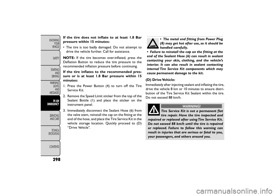
If the tire does not inflate to at least 1.8 Bar
pressure within 15 minutes:
• The tire is too badly damaged. Do not attempt todrive the vehicle further. Call for assistance.
NOTE: If the tire becomes over-inflated, press the
Deflation Button to reduce the tire pressure to the
recommended inflation pressure before continuing.
If the tire inflates to the recommended pres-
sure or is at least 1.8 Bar pressure within 15
minutes:
1. Press the Power Button (4) to turn off the Tire Service Kit.
2. Remove the Speed Limit sticker from the top of the Sealant Bottle (1) and place the sticker on the
instrument panel.
3. Immediately disconnect the Sealant Hose (6) from the valve stem, reinstall the cap on the fitting at the
end of the hose, and place the Tire Service Kit in the
vehicle storage location. Quickly proceed to (D)
“Drive Vehicle”.•The metal end fitting from Power Plug
(8) may get hot after use, so it should be
handled carefully.
• Failure to reinstall the cap on the fitting at the
end of the Sealant Hose (6) can result in sealant
contacting your skin, clothing, and the vehicle’s
interior. It can also result in sealant contacting
internal Tire Service Kit components which may
cause permanent damage to the kit .
(D) Drive Vehicle:
Immediately after injecting sealant and inflating the tire,
drive the vehicle 8 km or 10 minutes to ensure distri-
bution of the Tire Service Kit Sealant within the tire.
Do not exceed 88 km/h.
WARNING!
Tire Service Kit is not a permanent flat
tire re
pair. Have the tire inspected and
repaired or replaced after using Tire Service Kit .
Do not exceed 88 km/h until the tire is repaired
or replaced. Failure to follow this warning can
result in injuries that are serious or fatal to you,
your passengers, and others around you.
298
KNOWING YOUR
VEHICLE
SAFETY
STARTING AND
DRIVING
WARNING LIGHTSAND
MESSAGES
IN AN
EMERGENCY
SER VICING
AND
CARE
TECHNICAL
SPECIFICATIONS
CONTENTS
Page 306 of 412

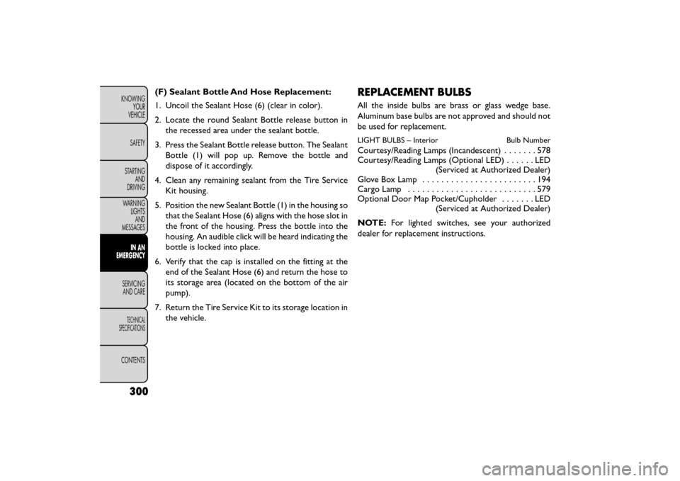
(F) Sealant Bottle And Hose Replacement:
1. Uncoil the Sealant Hose (6) (clear in color).
2. Locate the round Sealant Bottle release button inthe recessed area under the sealant bottle.
3. Press the Sealant Bottle release button. The Sealant Bottle (1) will pop up. Remove the bottle and
dispose of it accordingly.
4. Clean any remaining sealant from the Tire Service Kit housing.
5. Position the new Sealant Bottle (1) in the housing so that the Sealant Hose (6) aligns with the hose slot in
the front of the housing. Press the bottle into the
housing. An audible click will be heard indicating the
bottle is locked into place.
6. Verify that the cap is installed on the fitting at the end of the Sealant Hose (6) and return the hose to
its storage area (located on the bottom of the air
pump).
7. Return the Tire Service Kit to its storage location in the vehicle.REPLACEMENT BULBS
All the inside bulbs are brass or glass wedge base.
Aluminum base bulbs are not approved and should not
be used for replacement.
LIGHT BULBS – Interior Bulb Number
Courtesy/Reading Lamps (Incandescent).......578
Courtesy/Reading Lamps (Optional LED) ......LED
(Serviced at Authorized Dealer)
Glove Box Lamp ........................194
Cargo Lamp ...........................579
Optional Door Map Pocket/Cupholder .......LED
(Serviced at Authorized Dealer)
NOTE: For lighted switches, see your authorized
dealer for replacement instructions.
300
KNOWING YOUR
VEHICLE
SAFETY
STARTING AND
DRIVING
WARNING LIGHTSAND
MESSAGES
IN AN
EMERGENCY
SER VICING
AND
CARE
TECHNICAL
SPECIFICATIONS
CONTENTS
Page 314 of 412

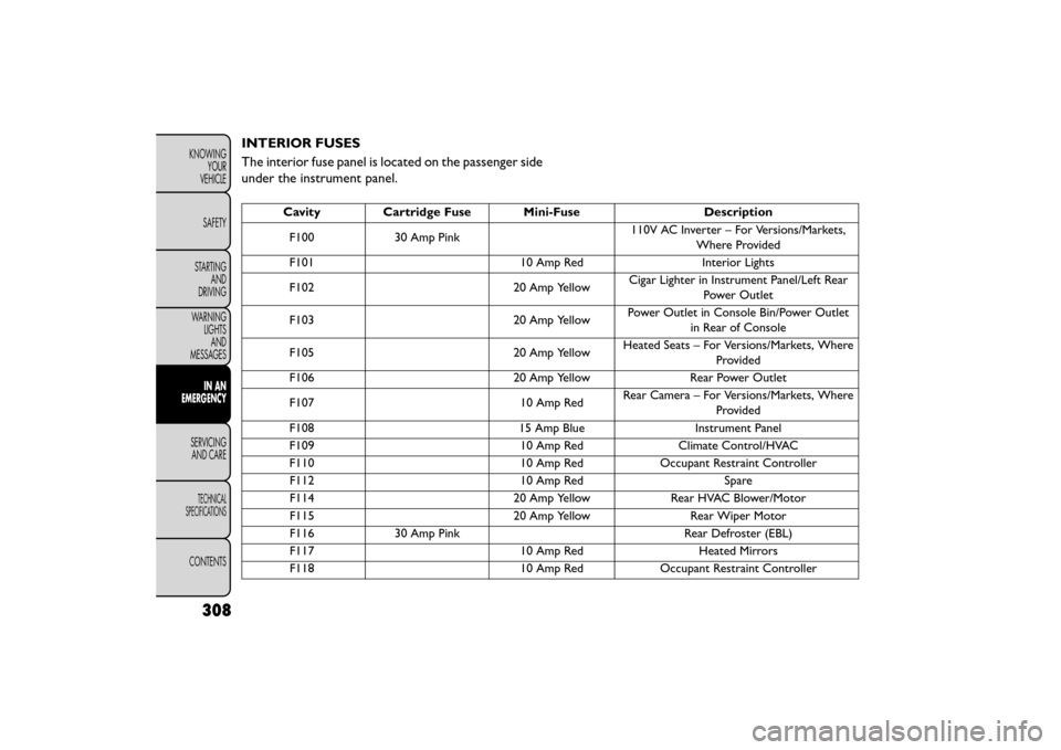
INTERIOR FUSES
The interior fuse panel is located on the passenger side
under the instrument panel.
CavityCartridge Fuse Mini-Fuse Description
F100 30 Amp Pink 110V AC Inverter – For Versions/Markets,
Where Provided
F101 10 Amp RedInterior Lights
F102 20 Amp YellowCigar Lighter in Instrument Panel/Left Rear
Power Outlet
F103 20 Amp YellowPower Outlet in Console Bin/Power Outlet
in Rear of Console
F105 20 Amp YellowHeated Seats – For Versions/Markets, Where
Provided
F106 20 Amp YellowRear Power Outlet
F107 10 Amp RedRear Camera – For Versions/Markets, Where
Provided
F108 15 Amp BlueInstrument Panel
F109 10 Amp RedClimate Control/HVAC
F110 10 Amp RedOccupant Restraint Controller
F112 10 Amp RedSpare
F114 20 Amp YellowRear HVAC Blower/Motor
F115 20 Amp YellowRear Wiper Motor
F116 30 Amp Pink Rear Defroster (EBL)
F117 10 Amp RedHeated Mirrors
F118 10 Amp RedOccupant Restraint Controller
308
KNOWING
YOUR
VEHICLE
SAFETY
STARTING AND
DRIVING
WARNING LIGHTSAND
MESSAGES
IN AN
EMERGENCY
SER VICING
AND
CARE
TECHNICAL
SPECIFICATIONS
CONTENTS
Page 316 of 412

UNDERHOOD FUSES (POWER
DISTRIBUTION CENTER)
The power distribution center is located in the engine
compartment.
(fig. 191)
Cavity Cartridge Fuse Mini-FuseDescription
F101 60 Amp Yellow Interior Power Distribution Center Rail
F102 60 Amp Yellow Interior Power Distribution Center Rail
F103 60 Amp Yellow Interior Power Distribution Center Rail
F105 60 Amp Yellow Interior Power Distribution Center Rail
Ignition Run Relay
F106 60 Amp Yellow Interior Power Distribution Center Rail Run/
Accessory Relays
F139 40 Amp Green Climate Control System Blower
F140 30 Amp Pink Power Locks
F141 40 Amp Green Anti-Lock Brake System
F142 40 Amp Green Glow Plugs – For Versions/Markets, Where
Provided
F143 40 Amp Green Exterior Lights 1
(fig. 191)
Power Distribution Center (Fuses)
310
KNOWINGYOUR
VEHICLE
SAFETY
STARTING AND
DRIVING
WARNING LIGHTSAND
MESSAGES
IN AN
EMERGENCY
SER VICING
AND
CARE
TECHNICAL
SPECIFICATIONS
CONTENTS