2015 FIAT FREEMONT instrument panel
[x] Cancel search: instrument panelPage 219 of 412

AIR BAG WARNING LIGHTThe air bags must be ready to inflate for your
protection in a collision. The Occupant Re-
straint Controller (ORC) monitors the inter-
nal circuits and interconnecting wiring asso-
ciated with air bag system electrical components.
The ORC monitors the readiness of the electronic
parts of the air bag system whenever the ignition
switch is in the START or ON/RUN position. If the
ignition switch is in the OFF position or in the ACC
position, the air bag system is not on and the air bags
will not inflate
The ORC contains a backup power supply system that
may deploy the air bags even if the battery loses power
or it becomes disconnected prior to deployment.
The ORC turns on the Air Bag Warning Light
in the
instrument panel for approximately four to eight sec-
onds for a self-check when the ignition switch is first
turned to the ON/RUN position. After the self-check,
the Air Bag Warning Light will turn off. If the ORC
detects a malfunction in any part of the system, it turns
on the Air Bag Warning Light, either momentarily or
continuously. A single chime will sound to alert you if
the light comes on again after initial startup. The ORC also includes diagnostics that will illuminate
the instrument panel Air Bag Warning Light if a mal-
function is detected that could affect the air bag sys-
tem. The diagnostics also record the nature of the
malfunction. While the air bag system is designed to be
maintenance free, if any of the following occurs, have an
authorized dealer service the air bag system immedi-
ately.
• The Air Bag Warning Light does not come on during
the four to eight seconds when the ignition switch is
first turned to the ON/RUN position.
• The Air Bag Warning Light remains on after the four to eight-second interval.
• The Air Bag Warning Light comes on intermittently or remains on while driving.
NOTE: If the speedometer, tachometer, or any engine
related gauges are not working, the Occupant Re-
straint Controller (ORC) may also be disabled. In this
condition the air bags may not be ready to inflate for
your protection. Have an authorized dealer service the
air bag system immediately.
213
KNOWING
YOUR
VEHICLE
SAFETY
STARTING
AND
DRIVING
WARNING
LIGHTS
AND
MESSAGES
IN
AN
EMERGENCY
SERVICING
AND CARE
TECHNICAL
SPECIFICATIONS
CONTENTS
Page 220 of 412

WARNING!
Ignoring the Air Bag Warning Light in
your ins
trument panel could mean you
won’t have the air bags to protect you in a
collision. If the light does not come on as a bulb
check when the ignition is first turned on, stays
on after you start the vehicle, or if it comes on as
you drive, have an authorized dealer service the
air bag system immediately.
MAINTAINING YOUR AIR BAG SYSTEM
WARNING!
• Modifications to any part of the air
bag sys
tem could cause it to fail when
you need it . You could be injured if the air bag
system is not there to protect you. Do not modify
the components or wiring, including adding any
kind of badges or stickers to the steering wheel
hub trim cover or the upper right side of the
instrument panel. Do not modify the front bum-
per, vehicle body structure, or add aftermarket
side steps or running boards.
(Continued)
WARNING! (Continued)
• It is dangerous to try to repair any part of the
air bag system yourself. Be sure to tell anyone
who works on your vehicle that it has an air bag
system.
• Do not attempt to modify any part of your air
bag system.The air bag may inflate accidentally
or may not function properly if modifications are
made.Take your vehicle to an authorized dealer
for any air bag system service. If your seat , includ-
ing your trim cover and cushion, needs to be
serviced in any way (including removal or
loosening/tightening of seat attachment bolts),
take the vehicle to your authorized dealer. Only
manufacturer approved seat accessories may be
used. If it is necessary to modify the air bag
system for persons with disabilities, contact your
authorized dealer.
214
KNOWING YOUR
VEHICLE
SAFETY
STARTING AND
DRIVING
WARNING LIGHTSAND
MESSAGES
IN
AN
EMERGENCY
SERVICINGAND CARE
TECHNICAL
SPECIFICATIONS
CONTENTS
Page 249 of 412

Automatic Transmission
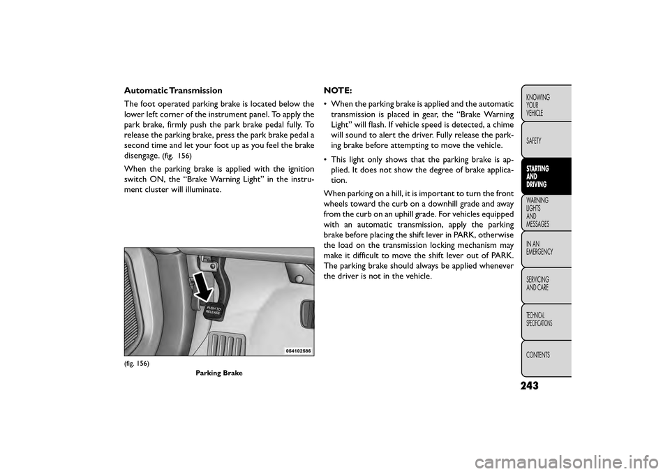
The foot operated parking brake is located below the
lower left corner of the instrument panel. To apply the
park brake, firmly push the park brake pedal fully. To
release the parking brake, press the park brake pedal a
second time and let your foot up as you feel the brake
disengage.
(fig. 156)
When the parking brake is applied with the ignition
switch ON, the “Brake Warning Light” in the instru-
ment cluster will illuminate.NOTE:
• When the parking brake is applied and the automatic
transmission is placed in gear, the “Brake Warning
Light” will flash. If vehicle speed is detected, a chime
will sound to alert the driver. Fully release the park-
ing brake before attempting to move the vehicle.
• This light only shows that the parking brake is ap- plied. It does not show the degree of brake applica-
tion.
When parking on a hill, it is important to turn the front
wheels toward the curb on a downhill grade and away
from the curb on an uphill grade. For vehicles equipped
with an automatic transmission, apply the parking
brake before placing the shift lever in PARK, otherwise
the load on the transmission locking mechanism may
make it difficult to move the shift lever out of PARK.
The parking brake should always be applied whenever
the driver is not in the vehicle.
(fig. 156) Parking Brake
243
KNOWING
YOUR
VEHICLE
SAFETY
STARTING
AND
DRIVING
WARNING
LIGHTS
AND
MESSAGES
INAN
EMERGENC
Y
SERVICING
AND CARE
TECHNICAL
SPECIFICATIONS
CONTENTS
Page 304 of 412

If the tire does not inflate to at least 1.8 Bar
pressure within 15 minutes:
• The tire is too badly damaged. Do not attempt todrive the vehicle further. Call for assistance.
NOTE: If the tire becomes over-inflated, press the
Deflation Button to reduce the tire pressure to the
recommended inflation pressure before continuing.
If the tire inflates to the recommended pres-
sure or is at least 1.8 Bar pressure within 15
minutes:
1. Press the Power Button (4) to turn off the Tire Service Kit.
2. Remove the Speed Limit sticker from the top of the Sealant Bottle (1) and place the sticker on the
instrument panel.
3. Immediately disconnect the Sealant Hose (6) from the valve stem, reinstall the cap on the fitting at the
end of the hose, and place the Tire Service Kit in the
vehicle storage location. Quickly proceed to (D)
“Drive Vehicle”.•The metal end fitting from Power Plug
(8) may get hot after use, so it should be
handled carefully.
• Failure to reinstall the cap on the fitting at the
end of the Sealant Hose (6) can result in sealant
contacting your skin, clothing, and the vehicle’s
interior. It can also result in sealant contacting
internal Tire Service Kit components which may
cause permanent damage to the kit .
(D) Drive Vehicle:
Immediately after injecting sealant and inflating the tire,
drive the vehicle 8 km or 10 minutes to ensure distri-
bution of the Tire Service Kit Sealant within the tire.
Do not exceed 88 km/h.
WARNING!
Tire Service Kit is not a permanent flat
tire re
pair. Have the tire inspected and
repaired or replaced after using Tire Service Kit .
Do not exceed 88 km/h until the tire is repaired
or replaced. Failure to follow this warning can
result in injuries that are serious or fatal to you,
your passengers, and others around you.
298
KNOWING YOUR
VEHICLE
SAFETY
STARTING AND
DRIVING
WARNING LIGHTSAND
MESSAGES
IN AN
EMERGENCY
SER VICING
AND
CARE
TECHNICAL
SPECIFICATIONS
CONTENTS
Page 314 of 412

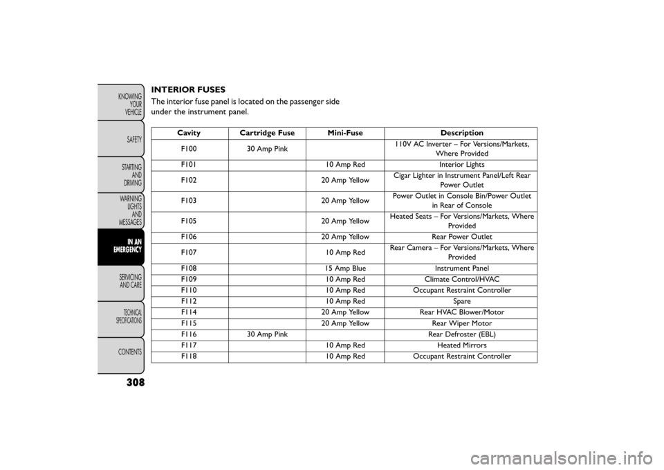
INTERIOR FUSES
The interior fuse panel is located on the passenger side
under the instrument panel.
CavityCartridge Fuse Mini-Fuse Description
F100 30 Amp Pink 110V AC Inverter – For Versions/Markets,
Where Provided
F101 10 Amp RedInterior Lights
F102 20 Amp YellowCigar Lighter in Instrument Panel/Left Rear
Power Outlet
F103 20 Amp YellowPower Outlet in Console Bin/Power Outlet
in Rear of Console
F105 20 Amp YellowHeated Seats – For Versions/Markets, Where
Provided
F106 20 Amp YellowRear Power Outlet
F107 10 Amp RedRear Camera – For Versions/Markets, Where
Provided
F108 15 Amp BlueInstrument Panel
F109 10 Amp RedClimate Control/HVAC
F110 10 Amp RedOccupant Restraint Controller
F112 10 Amp RedSpare
F114 20 Amp YellowRear HVAC Blower/Motor
F115 20 Amp YellowRear Wiper Motor
F116 30 Amp Pink Rear Defroster (EBL)
F117 10 Amp RedHeated Mirrors
F118 10 Amp RedOccupant Restraint Controller
308
KNOWING
YOUR
VEHICLE
SAFETY
STARTING AND
DRIVING
WARNING LIGHTSAND
MESSAGES
IN AN
EMERGENCY
SER VICING
AND
CARE
TECHNICAL
SPECIFICATIONS
CONTENTS
Page 315 of 412

CavityCartridge Fuse Mini-Fuse Description
F119 10 Amp RedSteering Column Control Module
F120 10 Amp RedAll Wheel Drive – For Versions/Markets,
Where Provided
F121 15 Amp BlueWireless Ignition Node
F122 25 Amp ClearDriver Door Module
F123 25 Amp ClearPassenger Door Module
F124 10 Amp RedMirrors
F125 10 Amp RedSteering Column Control Module
F126 10 Amp RedAudio Amplifier
F127 20 Amp YellowTrailer Tow – For Versions/Markets, Where
Provided
F128 15 Amp BlueRadio
F129 15 Amp BlueVideo/DVD – For Versions/Markets, Where
Provided
F130 15 Amp BlueClimate Control/Instrument Panel
F131 10 Amp RedPassenger Assistance/Hands Free System –
For Versions/Markets, Where Provided
F132 10 Amp RedTire Pressure Module
F133 10 Amp RedSpare
309
KNOWING
YOUR
VEHICLE
SAFETY
STARTING
AND
DRIVING
WARNING
LIGHTS
AND
MESSAGES
IN AN
EMERGENCY
SERVICING
AND
CARE
TECHNICAL
SPECIFICATIONS
CONTENTS
Page 328 of 412

Thousands Of Kilometers 15 30 45 60 75 90 105 120 135 150Years 1 2 3 4 5678910
Check tire condition/wear and adjust pressure, if
necessary, check TIREKIT expiration date (if
provided). ••••••••••
Check operation of lighting system (headlamps,
direction indicators, hazard warning lights,
luggage compartment, passenger compartment,
glove compartment, instrument panel warning
lights, etc.). ••••••••••
Check and, if necessary, top up fluid levels
(brakes/hydraulic clutch, windshield washer,
battery, engine coolant, etc.). ••••••••••
Check exhaust gas emissions/smokiness. • • • • ••••••
Using diagnosis socket, check operation of engine
management systems, emissions and (where
provided) engine oil deterioration. ••••••••••
Check windshield/rear window wiper blade
position/wear. •••••
Check operation of windshield washer system
and adjust jets if necessary. •••••
Check cleanliness of hood and tailgate locks and
cleanliness and lubrication of linkages. •••••
Check the parking brake lever stroke and adjust
it, if necessary. (Manual Transmission Only) ••••••••••
322
KNOWING
YOUR
VEHICLE
SAFETY
STARTING AND
DRIVING
WARNING LIGHTSAND
MESSAGES
IN AN
EMERGENCY
SERVICINGAND C ARE
TECHNICAL
SPECIFICATIONS
CONTENTS
Page 330 of 412

Thousands Of Kilometers 15 30 45 60 75 90 105 120 135 150Years 1 2 3 4 5678910
Replace rear drive assembly (RDA) fluid (for
versions/markets, where provided). •
Replace power transfer unit (PTU) fluid (for
versions/markets, where provided). •
Replace cabin filter. (#) ◦•◦ • ◦ •◦•◦•
Flush and replace the engine coolant. •
◦Recommend replacement.
(#) The air cleaner cartridge must be changed every
15,000 km if used in dusty areas.
(##)
Non-dusty/normal areas: advised maximum mileage
120,000 km. Regardless of the mileage, the belt must be
replaced every 6 years. Dusty areas and/or demanding use
(cold climates, town use, long periods of idling): advised
maximum mileage 60,000 km. Regardless of the mileage,
the belt must be replaced every 4 years.
(*)The oil and oil filter replacement must be carried out
when indicated by a warning light or message on the
instrument panel, or in any case should not exceed 1 year.
(**) The spark plug change is km based only, yearly
intervals do not apply.
(***) Change the automatic transmission fluid and
filter(s) at 75,000 km or 5 years if using your vehicle for
police, taxi, fleet, or frequent trailer towing. Periodic Checks
Every
1,000 km or before long journeys, check and, if
necessary, restore:
• engine coolant;
• brake fluid;
• power steering fluid;
• windshield washer fluid level;
• tire inflation pressure and condition;
• operation of lighting system (headlights, direction indicators, hazard warning lights, etc.);
• operation of windshield washer/wiper system and positioning/wear of windshield/rear window wiper
blades.
324
KNOWING YOUR
VEHICLE
SAFETY
STARTING AND
DRIVING
WARNING LIGHTSAND
MESSAGES
IN AN
EMERGENCY
SERVICINGAND C ARE
TECHNICAL
SPECIFICATIONS
CONTENTS