Page 84 of 367

WARNING
45) For safety reasons, the bonnet
must always be perfectly closed
while travelling. Make sure that
the bonnet is perfectly closed and
that the lock is engaged. If you
notice when driving that the
bonnet has not been properly
locked, stop immediately
and close the bonnet correctly.
46) Incorrect positioning of the stay
rod may cause the bonnet to drop
suddenly.
47) Perform these operations only
when the vehicle is stationary.
ROOF RACK/SKI
RACK
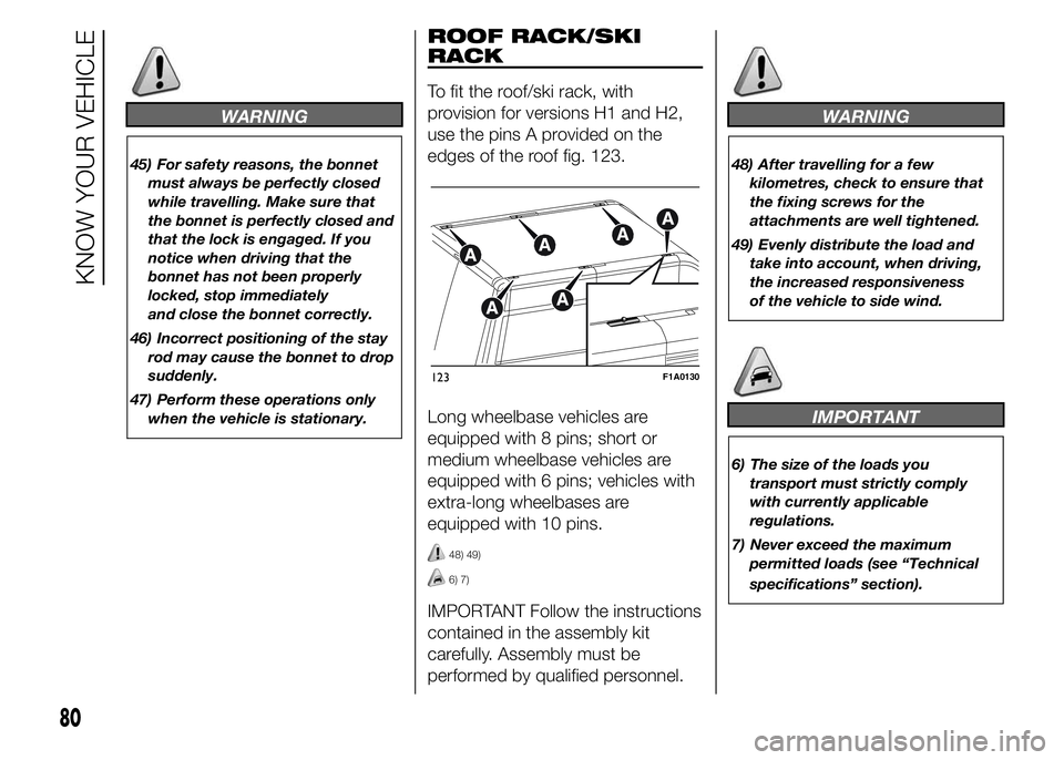
To fit the roof/ski rack, with
provision for versions H1 and H2,
use the pins A provided on the
edges of the roof fig. 123.
Long wheelbase vehicles are
equipped with 8 pins; short or
medium wheelbase vehicles are
equipped with 6 pins; vehicles with
extra-long wheelbases are
equipped with 10 pins.
48) 49)
6) 7)
IMPORTANT Follow the instructions
contained in the assembly kit
carefully. Assembly must be
performed by qualified personnel.
WARNING
48) After travelling for a few
kilometres, check to ensure that
the fixing screws for the
attachments are well tightened.
49) Evenly distribute the load and
take into account, when driving,
the increased responsiveness
of the vehicle to side wind.
IMPORTANT
6) The size of the loads you
transport must strictly comply
with currently applicable
regulations.
7) Never exceed the maximum
permitted loads (see “Technical
specifications” section).
123F1A0130
80
KNOW YOUR VEHICLE
Page 95 of 367

IMPORTANT
INFORMATION
WARNING
69) The TPMS is optimised for the
original tyres and wheels
provided. TPMS pressures and
alerts have been defined
according to the size of the tyres
mounted on the vehicle. Using
equipment with different size,
type or kind may cause irregular
system operation or sensor
damage. Non-original spare
wheels can damage the sensor.
Do not use tyre sealant or
balancing weights if the vehicle is
equipped with TPMS as these
may damage the sensors.
70) If the system signals a pressure
decrease on a specific tyre, it is
recommended to check the
pressure on all four tyres.
71) TPMS does not relieve the driver
from the obligation to check the
tyre pressure every month; it is
not even to be considered a
replacing system for maintenance
or a safety system.72) Tyre pressure must be checked
with tyres cold. Should it become
necessary for whatever reason
to check pressure with warm
tyres, do not reduce pressure
even if it is higher than the
prescribed value, but repeat the
check when tyres are cold.
73) The TPMS cannot indicate
sudden tyre pressure drops (for
example when a tyre bursts).
In this case, stop the car, braking
with caution and avoiding abrupt
steering.
74) The system only warns that the
tyre pressure is low: it is not able
to inflate them.
75) An insufficient tyre inflation
increases fuel consumption,
reduces the tread duration and
may affect the capacity of driving
safely.
76) Always refit the valve stem cap
after inspecting or adjusting tyre
pressure. This prevents dampness
or dirt from entering the valve
stem and thus the pressure
control sensor from being
damaged.77) The tyre repair kit (Fix&Go)
provided with the car (for
versions/markets, where
provided) is compatible with the
TPMS sensors; using sealants not
equivalent with that in the original
kit may adversely affect its
operation. If sealants not
equivalent with the original one
are used, it is recommended to
have the TPMS sensor operation
checked by a qualified repair
centre.
91
Page 206 of 367

❒take the kit from the tool bag, located
in the glove compartment;
❒the kit includes one bracket, three
special screws and one Allen
spanner, 10 size;
❒go to the rear side of the vehicle
where the spare wheel is located;
❒make sure to have fully unwound the
cable of the spare wheel lifting
device; take the bell and position it
inside the circular bracket fig. 190;
❒tighten the knob on the screw to
secure the bracket fig. 191.
❒lay the bracket on the inside of the
alloy rim fig. 192.
❒use the Allen spanner and tighten the
three special screws on the nuts of
the bracket fig. 193 locking the rim;❒introduce the assembled tool fig. 185
with the suitable extension B fig. 184
on the screw A fig. 184 of the spare
wheel housing manoeuvring device
and turn clockwise to lift the spare
wheel back up until it is fully
supported in its housing under the
platform, checking that the
attachment reference D fig. 187
appears in the window on the device;❒Check the correct position of the
replaced wheel under the platform
(the lifting system is equipped with a
clutch to limit the end of the stroke).
Incorrect positioning may jeopardise
safety;
❒place the removal tools back in the
tool bag / compartment;
❒place the tool box / compartment in
its housing under the passenger
seat.
151) 152)
190F1A0424
191F1A0425
192F1A0426
193F1A0385
202
IN AN EMERGENCY