2015 FIAT 500X change wheel
[x] Cancel search: change wheelPage 9 of 240

DASHBOARD1. Adjustable side air diffusers 2. Left stalk: direction indicators, main beam headlights, flashing, Lane change function 3. Instrument panel
4. Steering wheel controls: Cruise control, Speed Limiter 5. Right stalk: windscreen wiper/washer, rear window wiper/washer, rain sensor sensitivity
level setting 6. Display: radio /Uconnect™7. Start&Stop, Hazard warning lights, passenger airbag status LEDs 8. Upper refrigerated storage
compartment 9. Passenger front airbag 10. Adjustable central air diffusers 11. Lower glove compartment 12. Climate control system controls
13. Buttons on the central console: seat heating, steering wheel heating, control panel for USB port + AUX socket and SD Card reader (where
provided) 14. Knee bag 15. Ignition device (key or button) 16. Driver front airbag 17. Steering wheel controls: display menu, trip computer,
multimedia, phone, voice recognition 18. Control panel: light switch, headlight alignment corrector.
12
11
1
F1B0321C
7
15-12-2014 8:23 Pagina 7
Page 25 of 240

Automatic main beam headlights(where provided)
In order not to disturb other road users,
the main beam headlights are
automatically deactivated when
approaching vehicles travelling in the
opposite direction or when following a
vehicle travelling in the same direction.
This function can be set through the
display menu (see the instructions
in the "Display" paragraph, "Knowing
the instrument panel" chapter); the light
switch ring nut must be turned to
AUTO to activate.
The function is activated by pushing the
stalk toward the dashboard (stable
position); the
warning light comes
on in the instrument panel. The
warning light will also come on in
the instrument panel with main beam
headlights on. If the vehicle is turned off
with the setting described previously,
the automatic main beam headlight
function will need a new resetting: bring
back the stalk in the centre position
and then press it again towards the
instrument panel.
When the speed is higher than 40 km/h
and the function is active, if the stalk
is brought again to the stable central
position the function deactivates and
the main beam headlights turn off.When the speed is lower than 15 km/h
and the function is active, the system
automatically switches the main beam
headlights off.
If the stalk is moved from the stable
central position and pushed again
towards the dashboard in the stable
position, this is interpreted as a request
for fixed main beam headlights: the
warning light comes on in the
instrument panel and the main beam
headlights turn on until vehicle speed
exceeds 40 km/h again. When this
threshold is exceeded the function
activates again automatically and the
warning light comes on again
in the instrument panel.
To deactivate this function, rotate the
light switch ring nut to the
position.
DIRECTION INDICATORSBring left stalk A fig. 28 to the (stable)
position:
upwards: activates the right direction
indicator;
downwards: activates the left direction
indicator.
The
or
warning light respectively
will flash on the instrument panel.
The direction indicators switch
off automatically when the steering
wheel is straightened or when the
daytime running lights (DRL)/parking
lights are activated.
"Lane Change" functionIf you wish to signal a lane change while
running, place the left stalk in the
unstable position for less than half a
second.
The direction indicator on the side
selected will flash five times and then
switch off automatically.HEADLIGHT ALIGNMENT
ADJUSTMENT
Headlight alignment correctorThe headlight alignment corrector
operates with ignition device at MAR
and dipped headlights on.
To adjust rotate ring nut A fig. 29.
❒Position 0: one or two people on the
front seats;
❒Position 1: 4 or 5 passengers
❒Position 2: 4 or 5 passengers + load
in the boot29
F1B0038C
23
15-12-2014 8:23 Pagina 23
Page 43 of 240

DISPLAYDESCRIPTIONThe vehicle is equipped with a display
that can show useful information to the
driver while driving.
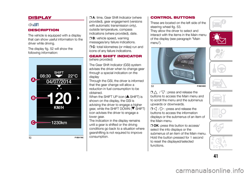
The display fig. 52 will show the
following information:❒A: time, Gear Shift Indicator (where
provided), gear engagement (versions
with automatic transmission only),
outside temperature, compass
indications (where provided), date.
❒B: vehicle speed, warning
messages/any failure indications.
❒C: total kilometres (or miles) run and
icons of any failure indications.
GEAR SHIFT INDICATOR(where provided)
The Gear Shift Indicator (GSI) system
advises the driver when to change gear
through a special indication on the
display
Through the GSI, the driver is informed
that the gear change will allow a
reduction in fuel consumption to be
obtained.
When the SHIFT UP icon (
SHIFT) is
shown on the display, the GSI is
advising the driver to engage a higher
gear, while the SHIFT DOWN (
SHIFT)
icon advises the driver to engage a
lower gear.
The indication in the display remains
until a gear is shifted or the driving
conditions go back to a situation where
gearshifting is not required to improve
consumption.
CONTROL BUTTONSThese are located on the left side of the
steering wheel fig. 53.
They allow the driver to select and
interact with the items in the Main menu
of the display (see paragraph "Main
menu").
❒
/
: press and release the
buttons to access the Main menu and
to scroll the menu and the submenus
upwards or downwards.
❒
/
: press and release the
buttons to access the information
displays or the submenus of an item of
the Main menu.
❒OK: press this button to access/
select the info displays or the
submenus of an item of the Main menu.
Hold the button pressed for 1 second
to reset the displayed/selected
functions.
08:30
KM/H
120
22°C
04/07/2014
1230km
52
F1B0179C
53
F1B0183C
41
15-12-2014 8:23 Pagina 41
Page 75 of 240

Low tyre pressureThe system warns the driver if one or
more tyres are flat by switching on
the
warning light on the instrument
panel and a warning message on
the display, along with an acoustic
signal. .
If the system does not recognise the
pressure value of one or more tyres, the
display will show dashes "– –"
This indication is displayed also when
turning the engine off and on again until
the RESET procedure is carried out.
Reset procedureThe iTPMS needs an initial "self-
learning" phase (with length depending
on the driving style and road conditions:
optimal conditions being driving on a
straight road at 80 km/h for at least 20
minutes) which starts when the RESET
procedure is carried out.
The RESET procedure must be carried
out:
❒whenever the tyre pressure is
modified;
❒when even only one tyre is changed;
❒when tyres are rotated/inverted;
❒when the space-saver wheel is fitted.Before carrying out the RESET
procedure, inflate the tyres to the rated
pressure values specified in the inflation
pressure table (see "Wheels" paragraph
in the "Technical specifications"
chapter).
If the RESET is not carried out, in all
above cases, the
warning light may
give false indications on one or more
tyres.
To carry out the RESET procedure, with
the vehicle stopped and the ignition
device at MAR, use the Main Menu as
follows:
❒go to "Vehicle info" and then to
"Reset tyre pressure"
❒press the "OK" and hold down (more
than 2 seconds)
❒the display will show the procedure
progress (with a graphic bar) till the
RESET is completed.
At the end of the RESET procedure the
display will show the "Reset saved"
message, indicating that the self-
learning has been started.
Working conditionsThe system is active for speeds above
15 km/h.In a few situations such as sporty
driving, particular conditions of the road
surface (e.g. icy, snowy, unsurfaced
roads...) the signalling may be delayed
or partial in detecting the contemporary
deflation of more than one tyre.
Under special conditions (e.g. vehicle
loaded asymmetrically on one side,
damaged or worn tyre, fitting the
space-saver wheel, fitting snow chains,
fitting different tyres on the axles) the
system may give false indications or be
temporarily deactivated.
If the system is temporarily deactivated
the
warning light flashes for about
75 seconds and then is continuously
on; at the same time, the display shows
a warning message.
This indication is displayed also after
the engine has been switched off and
then on again if the correct operating
conditions are not restored.
WARNING
57)The system is an aid for vehicle driving,
it DOES NOT warn the driver about
incoming vehicles outside of the detection
areas. The driver must always maintain a
sufficient level of attention to the traffic and
road conditions and for controlling the
trajectory of the vehicle.
73
15-12-2014 8:23 Pagina 73
Page 81 of 240

PRETENSIONERSThe vehicle is equipped with front seat
belt pretensioners, which draw back
the seat belts by several centimetres in
the event of a strong frontal impact.
This guarantees the perfect adherence
of the seat belts to the occupant's
bodies before the retention action
begins.
It is evident that the pretensioners have
been activated when the safety belt
withdraws toward the retractor.
This vehicle is also equipped with a
second pretensioner (in the kick plate
area). Its activation is signalled by
the shortening of the metal cable and
rolling up of the protective sheath.
A slight discharge of smoke may be
produced during the activation of the
pretensioner which is not harmful and
does not indicate any fire hazard.
The pretensioner does not require any
maintenance or lubrication: any
changes to its original conditions will
invalidate its efficiency.
If, due to unusual natural events (floods,
sea storms, etc.), the device has been
affected by water and/or mud, contact
a Fiat Dealership to have it replaced.IMPORTANT To obtain the highest
degree of protection from the action of
the pretensioner, wear the seat belt
tight to the torso and pelvis.
LOAD LIMITERS
72)32)
To increase safety in the event of an
accident, the front seat belt retractors
contain a load limiter which controls the
force acting on the chest and
shoulders during the belt restraining
action in the event of a head-on
collision.GENERAL
INSTRUCTIONS FOR
USING THE SEAT BELTS
73) 74) 75)
Respect and ensure that all the other
occupants of the vehicle comply with
the local laws in force regarding the use
of seat belts. Always fasten the seat
belts before setting off.
Seat belts must also be worn by
pregnant women: the risk of injury in
the event of an accident is reduced for
them and the unborn child if they are
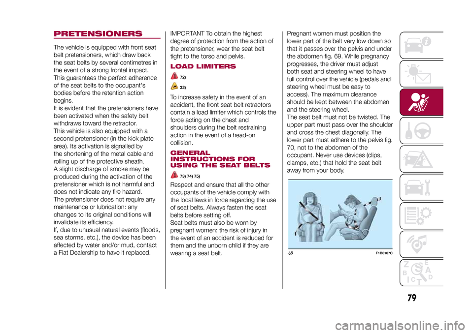
wearing a seat belt.Pregnant women must position the
lower part of the belt very low down so
that it passes over the pelvis and under
the abdomen fig. 69. While pregnancy
progresses, the driver must adjust
both seat and steering wheel to have
full control over the vehicle (pedals and
steering wheel must be easy to
access). The maximum clearance
should be kept between the abdomen
and the steering wheel.
The seat belt must not be twisted. The
upper part must pass over the shoulder
and cross the chest diagonally. The
lower part must adhere to the pelvis fig.
70, not to the abdomen of the
occupant. Never use devices (clips,
clamps, etc.) that hold the seat belt
away from your body.
69
F1B0107C
79
15-12-2014 8:23 Pagina 79
Page 135 of 240

CHANGING A WHEELJACKPlease note that:
❒the weight of the jack is 2.8 kg;
❒The jack requires no adjustment;
❒the jack cannot be repaired and in
the event of a fault it must be replaced
by another original one;
❒No tool other than its cranking device
may be fitted on the jack.CHANGING PROCEDURE
132) 133) 134) 135) 136) 137) 138) 139)
Proceed as follows:
❒stop the vehicle in a position that is
not dangerous for oncoming traffic
where you can change the wheel safely.
The ground should be flat if possible,
and sufficiently firm;
❒stop the engine, engage the hazard
warning lights and the electric parking
brake;
❒engage first gear or reverse or, for
versions with automatic transmission,
move the lever to position P (Park);
❒wear the reflective safety jacket
(compulsory by law in certain countries)
before getting out of the vehicle;❒open the boot and position the
reconfigurable load platform in
an inclined position (see "Boot" in the
"Knowing your vehicle" chapter);
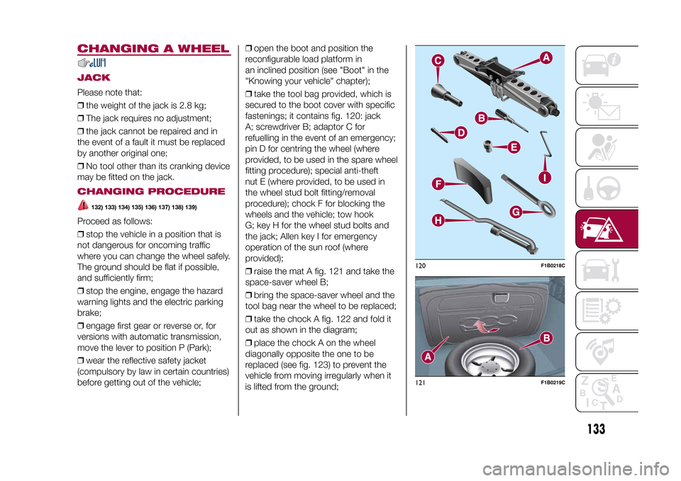
❒take the tool bag provided, which is
secured to the boot cover with specific
fastenings; it contains fig. 120: jack
A; screwdriver B; adaptor C for
refuelling in the event of an emergency;
pin D for centring the wheel (where
provided, to be used in the spare wheel
fitting procedure); special anti-theft
nut E (where provided, to be used in
the wheel stud bolt fitting/removal
procedure); chock F for blocking the
wheels and the vehicle; tow hook
G; key H for the wheel stud bolts and
the jack; Allen key I for emergency
operation of the sun roof (where
provided);
❒raise the mat A fig. 121 and take the
space-saver wheel B;
❒bring the space-saver wheel and the
tool bag near the wheel to be replaced;
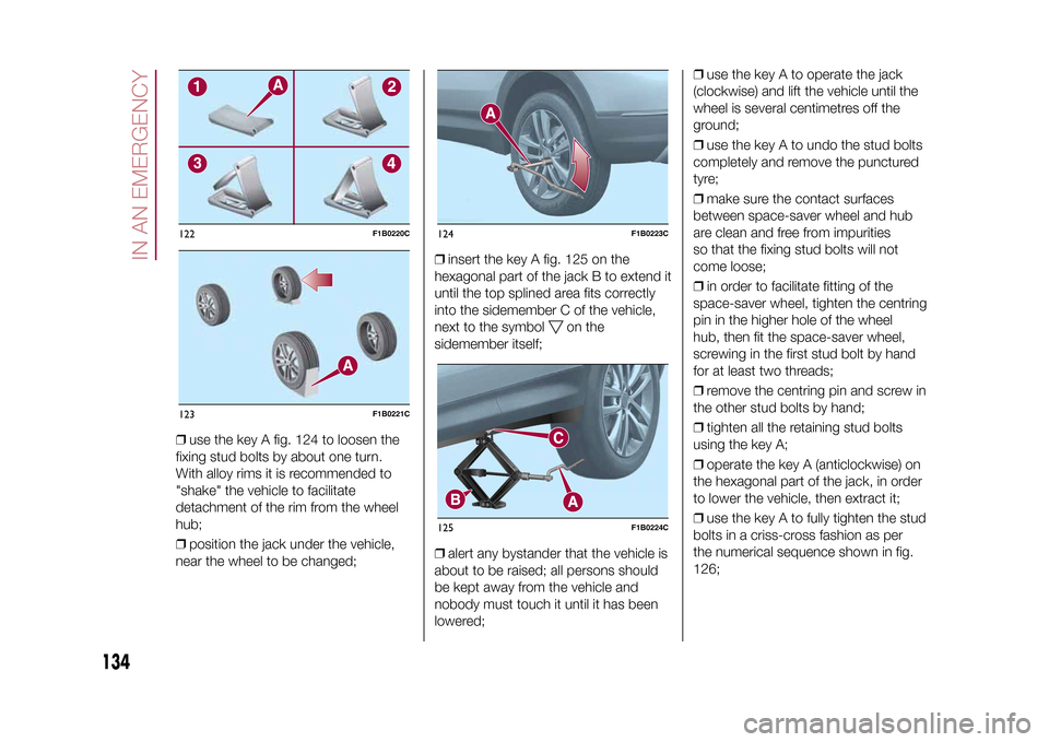
❒take the chock A fig. 122 and fold it
out as shown in the diagram;
❒place the chock A on the wheel
diagonally opposite the one to be
replaced (see fig. 123) to prevent the
vehicle from moving irregularly when it
is lifted from the ground;
120
F1B0218C
121
F1B0219C
133
15-12-2014 8:23 Pagina 133
Page 136 of 240

❒use the key A fig. 124 to loosen the
fixing stud bolts by about one turn.
With alloy rims it is recommended to
"shake" the vehicle to facilitate
detachment of the rim from the wheel
hub;
❒position the jack under the vehicle,
near the wheel to be changed;❒insert the key A fig. 125 on the
hexagonal part of the jack B to extend it
until the top splined area fits correctly
into the sidemember C of the vehicle,
next to the symbol
on the
sidemember itself;
❒alert any bystander that the vehicle is
about to be raised; all persons should
be kept away from the vehicle and
nobody must touch it until it has been
lowered;❒use the key A to operate the jack
(clockwise) and lift the vehicle until the
wheel is several centimetres off the
ground;
❒use the key A to undo the stud bolts
completely and remove the punctured
tyre;
❒make sure the contact surfaces
between space-saver wheel and hub
are clean and free from impurities
so that the fixing stud bolts will not
come loose;
❒in order to facilitate fitting of the
space-saver wheel, tighten the centring
pin in the higher hole of the wheel
hub, then fit the space-saver wheel,
screwing in the first stud bolt by hand
for at least two threads;
❒remove the centring pin and screw in
the other stud bolts by hand;
❒tighten all the retaining stud bolts
using the key A;
❒operate the key A (anticlockwise) on
the hexagonal part of the jack, in order
to lower the vehicle, then extract it;
❒use the key A to fully tighten the stud
bolts in a criss-cross fashion as per
the numerical sequence shown in fig.
126;
122
F1B0220C
123
F1B0221C
124
F1B0223C
125
F1B0224C
134
IN AN EMERGENCY
15-12-2014 8:23 Pagina 134
Page 137 of 240

❒place the punctured tyre in the boot
upside down (with the outer part facing
upwards), then reposition the jack
and the used tools;
❒reposition the boot mat then
reposition the reconfigurable load
platform in a flat position (see "Boot" in
the "Knowing your vehicle" chapter).
Restore the standard wheel as soon as
possible, because, once placed in the
associated compartment, the boot load
platform is rendered uneven as the
standard wheel is larger than the
space-saver wheel.
WARNING
132)If left in the passenger compartment,
the punctured wheel and jack constitute
a serious risk to the safety of occupants in
the event of accidents or sharp braking.
Therefore, always place both the jack and
punctured wheel in the dedicated housing
in the boot.
133)It is extremely dangerous to attempt
to change a wheel on the side of the
vehicle next to the driving lane: make sure
that the vehicle is at a sufficient distance
from the road, to avoid being run over.
134)Alert other drivers that the vehicle is
stationary in compliance with local
regulations: hazard warning lights, warning
triangle, etc. Any passengers on board
should leave the vehicle, especially if it is
heavily laden. Passengers should stay
away from on-coming traffic while the
wheel is being changed. For safety
reasons, always block the wheels with the
chocks provided.135)The vehicle's driving characteristics
will be modified with the space-saver wheel
fitted. Avoid violent acceleration and
braking, abrupt steering and fast cornering.
The overall duration of the space-saver
wheel is about 3000 km, after which the
relevant tyre must be replaced with another
one of the same type. Never install a
standard tyre on a rim that is designed for
use with a space-saver wheel. Have the
wheel repaired and refitted as soon as
possible. Using two or more space-saver
wheels at the same time is forbidden.
Do not grease the threads of the stud bolts
before fitting them: they might slip out
when driving!
136)The space-saver wheel is specific to
your vehicle: do not use it on other models,
or use the space-saver wheel of other
models on your vehicle. The space-saver
wheel must only be used in the event of an
emergency. It must only be used for the
distance necessary to reach a service point
and the vehicle speed must not exceed
80 km/h. The space-saver wheel has
an orange label that summarises the main
cautions for use and limitations. Never
remove or cover the sticker.
126
F1B0225C
135
15-12-2014 8:23 Pagina 135