2015 FIAT 500X Brake
[x] Cancel search: BrakePage 117 of 240

On some versions, a dedicated
message appears on the display when
it is activated and deactivated.Activation conditionsOnce switched on, the system
becomes active only if the following
conditions are met:
❒the driver always keeps at least one
hand on the steering wheel;
❒vehicle speed ranges between 60
km/h and 180 km/h;
❒the lane limit lines are perfectly visible
on both sides;
❒there are suitable visibility conditions;
❒the road is straight or with wide
radius bends;
❒a suitable distance is kept from the
vehicle in front;
❒the direction indicator (for leaving the
lane) is not active;❒the lane limit lines are perfectly visible
on both sides (for activation of the
tactile warning only).
NOTE The system does not apply the
vibration to the steering wheel every
time a safety system is activated
(brakes, ABS, ASR system, ESC
system, Full Brake Control system,
etc.).
WARNING
43)Projecting loads on the roof of the
vehicle may interfere with the correct
operation of the camera. Before starting
make sure the load is correctly positioned,
in order not to cover the camera operating
range.
44)If the windscreen must be replaced
due to scratches, chipping or breakage,
contact exclusively a Fiat Dealership.
Do not replace the windscreen on your
own, risk of malfunction! It is advisable to
replace the windscreen if it is damaged
in the area of the camera.
45)Do not tamper with nor operate on the
camera. Do not close the openings in
the aesthetic cover located under
the interior rear view mirror. In the event of
a failure of the camera, contact a Fiat
Dealership.
46)Do not cover the operating range of the
camera with stickers or other objects.
Also pay attention to other objects on the
bonnet (e.g. a layer of snow) and make
sure they do not interfere with the camera.47)The camera may have limited or absent
operation due to weather conditions such
as: heavy rain, hail, thick fog, heavy snow,
formation of ice layers on the windscreen.
48)Camera operation may also be
compromised by the presence of dust,
condensation, dirt or ice on the
windscreen, by traffic conditions (e.g.
vehicles that are driving not aligned with
yours, vehicle driving in a transverse or
opposite way on the same lane, bend with
a small radius of curvature), by road
surface conditions and by driving
conditions (e.g. off-road driving). Make sure
the windscreen is always clean. Use
specific detergents and clean cloths to
avoid scratching the windscreen. The
camera operation may also be limited or
absent in some driving, traffic and road
surface conditions.
98
F1B0334C
115
15-12-2014 8:23 Pagina 115
Page 118 of 240

REAR VIEW CAMERADESCRIPTIONThe camera A fig. 99 is located on the
tailgate.
119)49)
Every time reverse is engaged, the
display fig. 100 shows the area around
the vehicle, as seen by the rear camera.
SYMBOLS AND
MESSAGES ON THE
DISPLAYA superimposed central broken line
indicates the centre of the vehicle
to facilitate parking manoeuvres or tow
hook alignment. The various coloured
areas indicate the distance from the
rear of the vehicle.
The table below shows the
approximate distances for each area
fig. 100:
AreaDistance from the
rear of the vehicleRed (A) 0–30 cm
Yellow (B) 30–100 cm
Green (C) 1 m or more
IMPORTANT When parking, take the
utmost care over obstacles that may be
above or under the camera range.
WARNING
119)Parking and other potentially
dangerous manoeuvres are, however,
always the driver’s responsibility. While
carrying out these manoeuvres, always
make sure that no people (especially
children) or animals are in the area
concerned. The camera is an aid for the
driver, but the driver must never allow
his/her attention to lapse during potentially
dangerous manoeuvres, even those
executed at low speeds. Always maintain a
moderate speed, so as to be able to
brake promptly in the case of obstacles.
WARNING
49)It is vital, for correct operation, that the
camera is always kept clean and free
from mud, dirt, snow or ice. Be careful not
to scratch or damage the camera while
cleaning it. Avoid using dry, rough or hard
cloths. The camera must be washed
using clean water, with the addition of car
shampoo if necessary. In washing stations
which use steam or high-pressure jets,
clean the camera quickly, keeping the
nozzle more than 10 cm away from the
sensors. Do not apply stickers to the
camera.
99
F1B0064C
100
F1B0167C
116
STARTING AND DRIVING
15-12-2014 8:23 Pagina 116
Page 119 of 240
TOWING TRAILERSIMPORTANT
120) 121)
For towing caravans or trailers the
vehicle must be fitted with an approved
tow hook and an adequate electrical
system. Should aftermarket installation
be requested, this must be carried
out by specialists.
Install any specific and/or additional
door mirrors as specified by the
Highway Code.
Remember that when towing a trailer,
steep hills are harder to climb, braking
distances increase and overtaking
takes longer depending on the overall
weight of the trailer. Engage a low gear
when driving downhill, rather than
constantly using the brake. The weight
the trailer exerts on the vehicle tow
hook reduces the vehicle's loading
capacity by the same amount. To make
sure that the maximum towable weight
is not exceeded (given in the vehicle
registration document) account should
be taken of the fully laden trailer,
including accessories and luggage.
Do not exceed the speed limits specific
to each country you are driving in, in
the case of vehicles towing trailers.
In any case, the top speed must not
exceed 100 km/h.Any electric brake must be powered
directly by the battery through a cable
with a cross-section of no less than 2.5
mm
2. In addition to the electrical
branches, the vehicle electrical system
can only be connected to the supply
cable for an electric brake and to the
cable for an internal light for the trailer,
not exceeding 15 W. For connections,
use the preset control unit with a
battery cable with section not less than
2.5 mm
2. The use of auxiliary loads
other than external lights (e.g. electric
brake) must take place with engine
running.
INSTALLING A TOW
HOOKThe towing device should be fastened
to the body by specialised personnel
according to any additional and/or
integrative information supplied by the
Manufacturer of the device. It must also
meet current regulations with reference
to Directive 94/20/EC and subsequent
amendments.
For any version the towing device used
must be right for the towable weight
of the vehicle on which it is to be
installed.For the electrical connection a standard
connector should be used which is
generally placed on a special bracket
normally fastened to the towing device,
and a special ECU for external trailer
light control must be installed on the
vehicle. 7 or 13-pin 12 V DC
connections should be used (CUNA/
UNI and ISO/DIN Standards). Follow
any instructions provided by the vehicle
manufacturer and/or the towing device
manufacturer.
117
15-12-2014 8:23 Pagina 117
Page 120 of 240
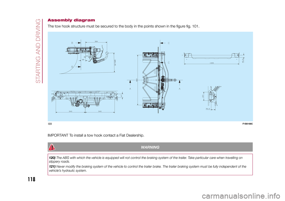
Assembly diagramThe tow hook structure must be secured to the body in the points shown in the figure fig. 101.
.
IMPORTANT To install a tow hook contact a Fiat Dealership.
WARNING
120)The ABS with which the vehicle is equipped will not control the braking system of the trailer. Take particular care when travelling on
slippery roads.
121)Never modify the braking system of the vehicle to control the trailer brake. The trailer braking system must be fully independent of the
vehicle’s hydraulic system.101
F1B0168C
118
STARTING AND DRIVING
15-12-2014 8:23 Pagina 118
Page 126 of 240
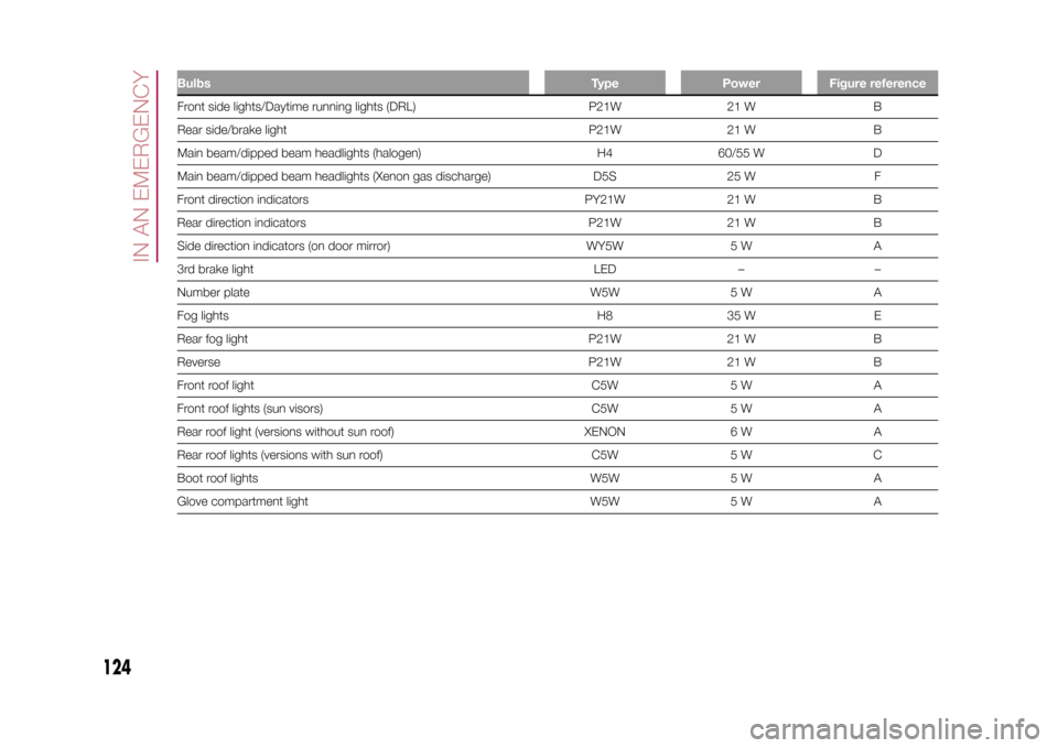
Bulbs Type Power Figure referenceFront side lights/Daytime running lights (DRL) P21W 21 W B
Rear side/brake light P21W 21 W B
Main beam/dipped beam headlights (halogen) H4 60/55 W D
Main beam/dipped beam headlights (Xenon gas discharge) D5S 25 W F
Front direction indicators PY21W 21 W B
Rear direction indicators P21W 21 W B
Side direction indicators (on door mirror) WY5W 5 W A
3rd brake light LED – –
Number plate W5W 5 W A
Fog lights H8 35 W E
Rear fog light P21W 21 W B
Reverse P21W 21 W B
Front roof light C5W 5 W A
Front roof lights (sun visors) C5W 5 W A
Rear roof light (versions without sun roof) XENON 6 W A
Rear roof lights (versions with sun roof) C5W 5 W C
Boot roof lights W5W 5 W A
Glove compartment light W5W 5 W A
124
IN AN EMERGENCY
15-12-2014 8:23 Pagina 124
Page 129 of 240
❒use the wrench A fig. 109 supplied
with the vehicle (located inside the case
with the on-board documentation),
undo the two screws A fig. 110, then
release the light cluster from the
relevant pin fastenings, pulling
cautiously;
❒disconnect the central connector B,
then undo the two screws C;
❒release the tabs indicated by the
arrows and extract the bulb holder
assembly D fig. 111;
❒identify the bulb to be replaced (1
Side/Stop - 2 Direction indicator -
3 Rear fog light or Reverse);
❒all bulbs are "bayonet-fitted";
therefore they must be lightly pressed
and simultaneously turned to be
replaced: anticlockwise for extraction,
clockwise for fitting;
❒correctly refit the bulb holder
assembly D in the light casing; stop
when you hear that the tabs click into
place;
❒tighten the two screws C fig. 110 and
reconnect the central connector B;
❒refit the lens unit, fully tightening the
two screws A;
❒reclose the tailgate.
3rd
brake lights
The 3
rd
brake lights are LED-based. For
their replacement, contact a Fiat
Dealership.
Number plate lightsTo replace the bulbs proceed as
follows:
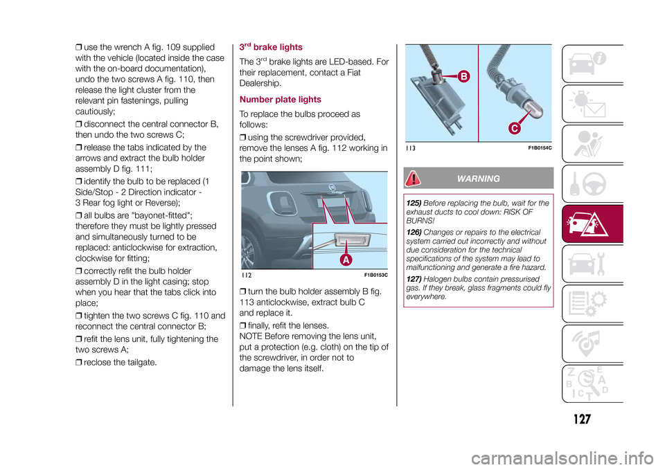
❒using the screwdriver provided,
remove the lenses A fig. 112 working in
the point shown;
❒turn the bulb holder assembly B fig.
113 anticlockwise, extract bulb C
and replace it.
❒finally, refit the lenses.
NOTE Before removing the lens unit,
put a protection (e.g. cloth) on the tip of
the screwdriver, in order not to
damage the lens itself.
WARNING
125)Before replacing the bulb, wait for the
exhaust ducts to cool down: RISK OF
BURNS!
126)Changes or repairs to the electrical
system carried out incorrectly and without
due consideration for the technical
specifications of the system may lead to
malfunctioning and generate a fire hazard.
127)Halogen bulbs contain pressurised
gas. If they break, glass fragments could fly
everywhere.
112
F1B0153C
113
F1B0154C
127
15-12-2014 8:23 Pagina 127
Page 135 of 240
CHANGING A WHEELJACKPlease note that:
❒the weight of the jack is 2.8 kg;
❒The jack requires no adjustment;
❒the jack cannot be repaired and in
the event of a fault it must be replaced
by another original one;
❒No tool other than its cranking device
may be fitted on the jack.CHANGING PROCEDURE
132) 133) 134) 135) 136) 137) 138) 139)
Proceed as follows:
❒stop the vehicle in a position that is
not dangerous for oncoming traffic
where you can change the wheel safely.
The ground should be flat if possible,
and sufficiently firm;
❒stop the engine, engage the hazard
warning lights and the electric parking
brake;
❒engage first gear or reverse or, for
versions with automatic transmission,
move the lever to position P (Park);
❒wear the reflective safety jacket
(compulsory by law in certain countries)
before getting out of the vehicle;❒open the boot and position the
reconfigurable load platform in
an inclined position (see "Boot" in the
"Knowing your vehicle" chapter);
❒take the tool bag provided, which is
secured to the boot cover with specific
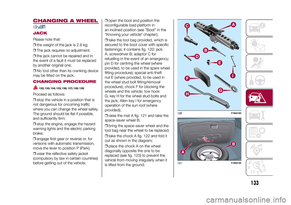
fastenings; it contains fig. 120: jack
A; screwdriver B; adaptor C for
refuelling in the event of an emergency;
pin D for centring the wheel (where
provided, to be used in the spare wheel
fitting procedure); special anti-theft
nut E (where provided, to be used in
the wheel stud bolt fitting/removal
procedure); chock F for blocking the
wheels and the vehicle; tow hook
G; key H for the wheel stud bolts and
the jack; Allen key I for emergency
operation of the sun roof (where
provided);
❒raise the mat A fig. 121 and take the
space-saver wheel B;
❒bring the space-saver wheel and the
tool bag near the wheel to be replaced;
❒take the chock A fig. 122 and fold it
out as shown in the diagram;
❒place the chock A on the wheel
diagonally opposite the one to be
replaced (see fig. 123) to prevent the
vehicle from moving irregularly when it
is lifted from the ground;
120
F1B0218C
121
F1B0219C
133
15-12-2014 8:23 Pagina 133
Page 138 of 240
137)The jack is a tool developed and
designed only for changing a wheel, if a
tyre gets punctured or damaged, on the
vehicle with which it is supplied or on other
vehicles of the same model. It must not
be used, for example, to jack other vehicle
models or objects. Never use the jack to
carry out maintenance or repairs under the
vehicle. Never position yourself under a
jacked vehicle. Should it be necessary to
work under the vehicle, contact a Fiat
Dealership. Incorrectly positioning the jack
may cause the vehicle to fall: use it only
in the positions indicated. Do not use the
jack for loads higher than the one shown
on its label.
138)The space-saver wheel cannot be
fitted with snow chains. If a front (drive) tyre
is punctured and chains are needed, use
a standard wheel from the rear axle and
install the space-saver wheel on the rear
axle. In this way, with two normal drive
wheels at the front axle, it is possible to use
snow chains (this instruction is also valid
for 4x4 versions).
139)Never tamper with the inflation valve.
Never introduce tools of any kind between
the rim and the tyre. Check tyre and
space-saver wheel pressures regularly,
complying with the values given in the
"Technical specifications" chapter.
FIX&GO AUTOMATIC
KIT(where provided)DESCRIPTION
140) 141) 142) 143) 144) 145) 146) 147)54)3)
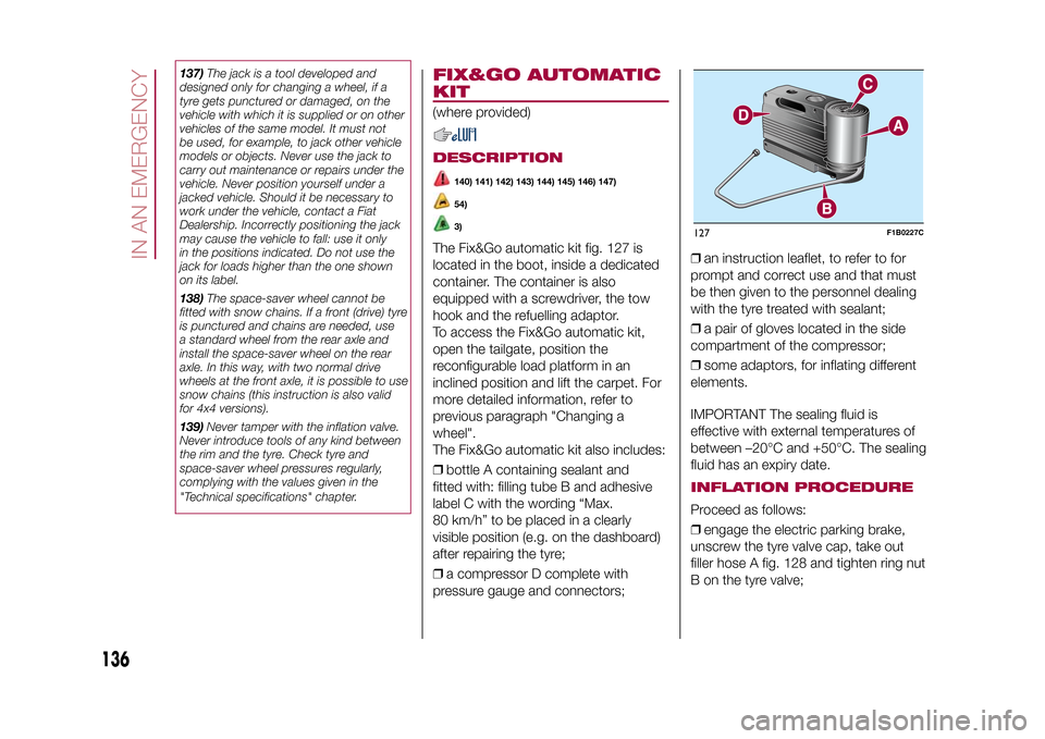
The Fix&Go automatic kit fig. 127 is
located in the boot, inside a dedicated
container. The container is also
equipped with a screwdriver, the tow
hook and the refuelling adaptor.
To access the Fix&Go automatic kit,
open the tailgate, position the
reconfigurable load platform in an
inclined position and lift the carpet. For
more detailed information, refer to
previous paragraph "Changing a
wheel".
The Fix&Go automatic kit also includes:
❒bottle A containing sealant and
fitted with: filling tube B and adhesive
label C with the wording “Max.
80 km/h” to be placed in a clearly
visible position (e.g. on the dashboard)
after repairing the tyre;
❒a compressor D complete with
pressure gauge and connectors;❒an instruction leaflet, to refer to for
prompt and correct use and that must
be then given to the personnel dealing
with the tyre treated with sealant;
❒a pair of gloves located in the side
compartment of the compressor;
❒some adaptors, for inflating different
elements.
IMPORTANT The sealing fluid is
effective with external temperatures of
between –20°C and +50°C. The sealing
fluid has an expiry date.
INFLATION PROCEDUREProceed as follows:
❒engage the electric parking brake,
unscrew the tyre valve cap, take out
filler hose A fig. 128 and tighten ring nut
B on the tyre valve;127
F1B0227C
136
IN AN EMERGENCY
15-12-2014 8:23 Pagina 136