Page 88 of 240

SUITABILITY OF
PASSENGER SEATS FOR
i-Size CHILD RESTRAINT
SYSTEM USEThe rear side seats of the vehicle are
type-approved to house the state-
of-the-art i-Size child restraint systems.
These child restraint systems, built
and type-approved according to the
i-Size (ECE R129) standard, ensure
better safety conditions to carry
children on board a vehicle:
❒the child must be transported
rearward facing until 15 months;
❒child restraint system protection is
increased in the event of a side
collision;
❒the use of the ISOFIX system is
promoted to avoid faulty installation of
the child restraint system;
❒efficiency in the choice of the child
restraint system, which isn't made
according to weight anymore but
according to the child's height,
is increased;
❒compatibility between the vehicle
seats and the child restraint systems is
better: the i-Size child restraint systems
can be considered as "Super ISOFIX";
this means that they can be perfectly
fitted in type-approved i-Size seats, but
can also be fitted in ISOFIX (ECE R44)
type-approved seats.NOTE The vehicle seats, i-Size
type-approved, are marked by the
symbol shown in fig. 80.
80
F1B0124C
86
SAFETY
15-12-2014 8:23 Pagina 86
Page 90 of 240
CHILD RESTRAINT SYSTEMS RECOMMENDED BY FCA FOR YOUR FIAT 500XLineaccessori MOPAR
®includes a complete range of child restraint systems to be fixed using the seat belt with three
anchorage points or the ISOFIX anchorages.
IMPORTANT FCA recommends fitting the child restraint system according to the instructions, which must be included.
Weight group Child restraint system Type of child restraint system Child restraint system installationGroup 0+: from birth
to 13 kg
Peg Perego Primo Viaggio SL
Type-approval number: E24
040089
Universal/ISOFIX child restraint system.
It must be installed rearward facing,
using the vehicle seat belts only, or the
dedicated ISOFIX K base (which can
be purchased separately) and the
vehicle ISOFIX anchorages.
It must be fitted on the rear outer
seats.ISOFIX K base
88
SAFETY
15-12-2014 8:23 Pagina 88
++
Page 91 of 240
Weight group Child restraint system Type of child restraint system Child restraint system installationGroup 1: from 9 up
to 18 kg
Fair G0/1S
Type-approval number: E4
04443718
Universal/ISOFIX child restraint system.
It can be fitted forward facing/rearward
facing using only the vehicle seat belts
or the Isofix anchorages.
FCA recommends fitting it using the
rearward facing ISOFIX platform (RWF
specific for Fiat 500X - to be
purchased separately) or the forward
facing ISOFIX platform (FWF specific
for Fiat 500X - to be purchased
separately), the rigid head restraint (to
be purchased separately) and the
ISOFIX anchorages for the vehicle.
It must be fitted on the rear outer
seats. ++A: Fair ISOFIX RWF platform,
Fiat 500X type specific for
G0/1S
or
B: Fair ISOFIX FWF platform,
Fiat 500X type specific for
G0/1S
++FAIR head restraint
89
15-12-2014 8:23 Pagina 89
Page 92 of 240
Weight group Child restraint system Type of child restraint system Child restraint system installationGroup 2: from 15 kg
to 36 kg
Fair Junior Fix
Type-approval number: E4
04443721It can only be fitted facing forwards,
using the three-point seat belt and the
ISOFIX anchorages of the vehicle, if
present.
90
SAFETY
15-12-2014 8:23 Pagina 90
Page 119 of 240

TOWING TRAILERSIMPORTANT
120) 121)
For towing caravans or trailers the
vehicle must be fitted with an approved
tow hook and an adequate electrical
system. Should aftermarket installation
be requested, this must be carried
out by specialists.
Install any specific and/or additional
door mirrors as specified by the
Highway Code.
Remember that when towing a trailer,
steep hills are harder to climb, braking
distances increase and overtaking
takes longer depending on the overall
weight of the trailer. Engage a low gear
when driving downhill, rather than
constantly using the brake. The weight
the trailer exerts on the vehicle tow
hook reduces the vehicle's loading
capacity by the same amount. To make
sure that the maximum towable weight
is not exceeded (given in the vehicle
registration document) account should
be taken of the fully laden trailer,
including accessories and luggage.
Do not exceed the speed limits specific
to each country you are driving in, in
the case of vehicles towing trailers.
In any case, the top speed must not
exceed 100 km/h.Any electric brake must be powered
directly by the battery through a cable
with a cross-section of no less than 2.5
mm
2. In addition to the electrical
branches, the vehicle electrical system
can only be connected to the supply
cable for an electric brake and to the
cable for an internal light for the trailer,
not exceeding 15 W. For connections,
use the preset control unit with a
battery cable with section not less than
2.5 mm
2. The use of auxiliary loads
other than external lights (e.g. electric
brake) must take place with engine
running.
INSTALLING A TOW
HOOKThe towing device should be fastened
to the body by specialised personnel
according to any additional and/or
integrative information supplied by the
Manufacturer of the device. It must also
meet current regulations with reference
to Directive 94/20/EC and subsequent
amendments.
For any version the towing device used
must be right for the towable weight
of the vehicle on which it is to be
installed.For the electrical connection a standard
connector should be used which is
generally placed on a special bracket
normally fastened to the towing device,
and a special ECU for external trailer
light control must be installed on the
vehicle. 7 or 13-pin 12 V DC
connections should be used (CUNA/
UNI and ISO/DIN Standards). Follow
any instructions provided by the vehicle
manufacturer and/or the towing device
manufacturer.
117
15-12-2014 8:23 Pagina 117
Page 135 of 240

CHANGING A WHEELJACKPlease note that:
❒the weight of the jack is 2.8 kg;
❒The jack requires no adjustment;
❒the jack cannot be repaired and in
the event of a fault it must be replaced
by another original one;
❒No tool other than its cranking device
may be fitted on the jack.CHANGING PROCEDURE
132) 133) 134) 135) 136) 137) 138) 139)
Proceed as follows:
❒stop the vehicle in a position that is
not dangerous for oncoming traffic
where you can change the wheel safely.
The ground should be flat if possible,
and sufficiently firm;
❒stop the engine, engage the hazard
warning lights and the electric parking
brake;
❒engage first gear or reverse or, for
versions with automatic transmission,
move the lever to position P (Park);
❒wear the reflective safety jacket
(compulsory by law in certain countries)
before getting out of the vehicle;❒open the boot and position the
reconfigurable load platform in
an inclined position (see "Boot" in the
"Knowing your vehicle" chapter);
❒take the tool bag provided, which is
secured to the boot cover with specific
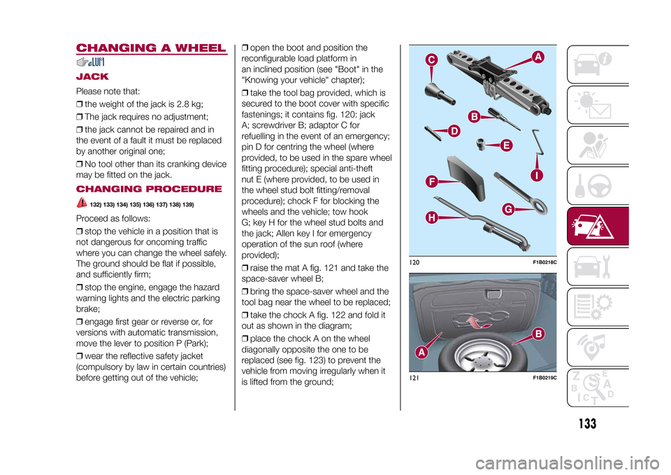
fastenings; it contains fig. 120: jack
A; screwdriver B; adaptor C for
refuelling in the event of an emergency;
pin D for centring the wheel (where
provided, to be used in the spare wheel
fitting procedure); special anti-theft
nut E (where provided, to be used in
the wheel stud bolt fitting/removal
procedure); chock F for blocking the
wheels and the vehicle; tow hook
G; key H for the wheel stud bolts and
the jack; Allen key I for emergency
operation of the sun roof (where
provided);
❒raise the mat A fig. 121 and take the
space-saver wheel B;
❒bring the space-saver wheel and the
tool bag near the wheel to be replaced;
❒take the chock A fig. 122 and fold it
out as shown in the diagram;
❒place the chock A on the wheel
diagonally opposite the one to be
replaced (see fig. 123) to prevent the
vehicle from moving irregularly when it
is lifted from the ground;
120
F1B0218C
121
F1B0219C
133
15-12-2014 8:23 Pagina 133
Page 174 of 240
TECHNICAL SPECIFICATIONS
Everything you may find useful for
understanding how your vehicle
is made and works is contained in this
chapter and illustrated with data, tables
and graphics. For the enthusiasts and
the technician, but also just for those
who want to know every detail of their
vehicle.IDENTIFICATION DATA....................173
ENGINE ..........................................174
WHEELS .........................................176
DIMENSIONS ..................................178
WEIGHTS........................................180
SUPPLIES .......................................182
FLUIDS AND LUBRICANTS ............184
PERFORMANCE .............................186
FUEL CONSUMPTION ....................186
CO2 EMISSIONS ............................188
PRESCRIPTIONS FOR HANDLING
THE VEHICLE AT THE END OF ITS
LIFE ................................................189
172
TECHNICAL SPECIFICATIONS
15-12-2014 8:23 Pagina 172
Page 175 of 240

IDENTIFICATION
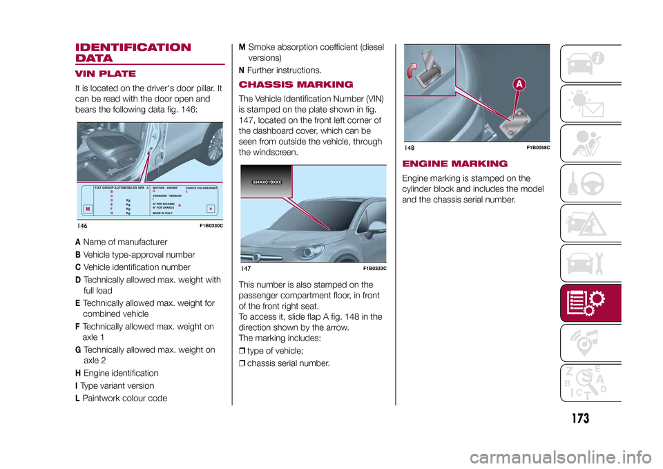
DATAVIN PLATEIt is located on the driver's door pillar. It
can be read with the door open and
bears the following data fig. 146:A
Name of manufacturer
B
Vehicle type-approval number
C
Vehicle identification number
D
Technically allowed max. weight with
full load
ETechnically allowed max. weight for
combined vehicleFTechnically allowed max. weight on
axle 1G
Technically allowed max. weight on
axle 2
H
Engine identification
IType variant versionLPaintwork colour code
M
Smoke absorption coefficient (diesel
versions)
N
Further instructions.
CHASSIS MARKINGThe Vehicle Identification Number (VIN)
is stamped on the plate shown in fig.
147, located on the front left corner of
the dashboard cover, which can be
seen from outside the vehicle, through
the windscreen.
This number is also stamped on the
passenger compartment floor, in front
of the front right seat.
To access it, slide flap A fig. 148 in the
direction shown by the arrow.
The marking includes:
❒type of vehicle;
❒chassis serial number.
ENGINE MARKINGEngine marking is stamped on the
cylinder block and includes the model
and the chassis serial number.
146
F1B0330C
334AXC1BXXX
334AXC1BXXX
147
F1B0333C
148
F1B0058C
173
15-12-2014 8:23 Pagina 173