2015 FIAT 500X mirror
[x] Cancel search: mirrorPage 70 of 240

The system activation is signalled to the
driver by means of a visual and
acoustic warning.
IMPORTANT If the sensors are covered
by objects or vehicles, the system will
not warn the driver.Operating modeThe system can be activated/
deactivated by operating on the display
Menu, or via theUconnect™system
(for further information see the
dedicated Supplement)."Blind Spot Assist", "Visual" modeWhen this mode is active, the BSA
system sends a visual warning to the
relevant door mirror, depending on the
detected object.
However, when operating in RCP
mode, the system sends visual and
acoustic warnings when the presence
of an object is detected.
When an acoustic warning is sent, the
Uconnect™volume is lowered."Blind Spot Assist", "Visual and
acoustic" modeWhen this mode has been activated,
the BSA system sends a visual warning
to the relevant door mirror, depending
on the detected object.If the direction indicator on the side
where an obstacle has been detected is
activated, an acoustic warning is
emitted as well.
When a direction indicator is active and
an object is simultaneously detected
on the same side, both the acoustic
and visual warnings are emitted. The
Uconnect™volume is also lowered.
During "RCP" operating mode, the
system sends acoustic and visual
warnings if the presence of an object is
detected. When an acoustic warning
is sent, theUconnect™volume is also
lowered.
"Blind Spot Assist" function
deactivationWhen the system is deactivated ("Blind
spot alert" mode at "OFF"), the BSA
or RCP systems will not emit neither
acoustic nor visual warnings.
The BSA system will store the operating
mode running when the engine was
switched off. Each time the engine
is started, the operating mode stored
previously will be recalled and used.IMPORTANT The system is an aid for
vehicle driving, it DOES NOT warn
the driver about incoming vehicles
outside of the detection areas. The
driver must always maintain a sufficient
level of attention to the traffic and
road conditions and for controlling the
trajectory of the vehicle.
FULL BRAKE CONTROL
SYSTEM
58) 59) 60) 61)22) 23) 24) 25) 26) 27) 28) 29) 30)
The vehicle can be equipped with the
"Full Brake Control" system. This is
a driving assistance system which
comprises a radar located behind the
front bumper fig. 57 and a camera
located in the central part of the
windscreen fig. 58.57
F1B0095C
68
SAFETY
15-12-2014 8:23 Pagina 68
Page 102 of 240

STARTING THE
ENGINEBefore starting the engine, adjust the
seat, the interior rear view mirrors,
the door mirrors and fasten the seat
belt correctly.
Never press the accelerator pedal for
starting the engine.
If necessary, messages indicating the
starting procedure can be shown on
the display.ENGINE STARTING
PROCEDURE
103) 104) 105) 106)33) 34) 35) 36)
Versions with manual gearboxProceed as follows:
❒engage the electric parking brake
and place the gear lever in neutral;
❒bring the ignition device to MAR. On
Diesel versions, warning light
lights up in the instrument panel:
wait for the warning light to switch off;
❒fully depress the clutch pedal without
touching the accelerator;
❒turn the ignition device to AVV and
release it as soon as the engine starts;❒if the engine does not start within 10
seconds, bring the ignition device
back to STOP and wait for 10-15
seconds before repeating the starting
procedure.
❒after the manoeuvre has been
repeated, if the problem persists,
contact a Fiat Dealership.
Versions with automatic
transmissionProceed as follows:
❒engage
the electric parking brake
and set the gear lever to P (Park) or N
(Neutral);
❒fully depress the brake pedal without
touching the accelerator;
❒set the ignition device to AVV;
❒if the engine does not start, bring the
ignition device back to STOP and
wait for 10-15 seconds before
repeating the starting procedure;
❒after the manoeuvre has been
repeated, if the problem persists,
contact a Fiat Dealership.
ENGINE STARTING
F
AILURE
Starting the engine with electronic
key battery (Keyless Go) run down
or flatIf the ignition device does not respond
when the relevant button is pressed the
electronic key battery might be run
down or flat. Therefore, the system
does not detect the presence of the
electronic key on board the vehicle and
displays a dedicated message. In this
case, rest the rounded edge of the
electronic key (the side opposite the
metal insert) on the ignition device and
press the button using the electronic
key. The ignition device is thus
activated and the engine can be
started.
WARNING
103)Do not try to start the engine by
pouring fuel or other flammable fluid inside
the throttle body air intake: this might
damage the engine and injury people
nearby.
104)It is dangerous to run the engine in
enclosed areas. The engine consumes
oxygen and produces carbon dioxide,
carbon monoxide and other toxic gases.
105)The brake servo is not operational
until the engine has been started; therefore
you need to apply much more force than
usual to the brake pedal.
100
STARTING AND DRIVING
12-1-2015 15:6 Pagina 100
Page 117 of 240

On some versions, a dedicated
message appears on the display when
it is activated and deactivated.Activation conditionsOnce switched on, the system
becomes active only if the following
conditions are met:
❒the driver always keeps at least one
hand on the steering wheel;
❒vehicle speed ranges between 60
km/h and 180 km/h;
❒the lane limit lines are perfectly visible
on both sides;
❒there are suitable visibility conditions;
❒the road is straight or with wide
radius bends;
❒a suitable distance is kept from the
vehicle in front;
❒the direction indicator (for leaving the
lane) is not active;❒the lane limit lines are perfectly visible
on both sides (for activation of the
tactile warning only).
NOTE The system does not apply the
vibration to the steering wheel every
time a safety system is activated
(brakes, ABS, ASR system, ESC
system, Full Brake Control system,
etc.).
WARNING
43)Projecting loads on the roof of the
vehicle may interfere with the correct
operation of the camera. Before starting
make sure the load is correctly positioned,
in order not to cover the camera operating
range.
44)If the windscreen must be replaced
due to scratches, chipping or breakage,
contact exclusively a Fiat Dealership.
Do not replace the windscreen on your
own, risk of malfunction! It is advisable to
replace the windscreen if it is damaged
in the area of the camera.
45)Do not tamper with nor operate on the
camera. Do not close the openings in
the aesthetic cover located under
the interior rear view mirror. In the event of
a failure of the camera, contact a Fiat
Dealership.
46)Do not cover the operating range of the
camera with stickers or other objects.
Also pay attention to other objects on the
bonnet (e.g. a layer of snow) and make
sure they do not interfere with the camera.47)The camera may have limited or absent
operation due to weather conditions such
as: heavy rain, hail, thick fog, heavy snow,
formation of ice layers on the windscreen.
48)Camera operation may also be
compromised by the presence of dust,
condensation, dirt or ice on the
windscreen, by traffic conditions (e.g.
vehicles that are driving not aligned with
yours, vehicle driving in a transverse or
opposite way on the same lane, bend with
a small radius of curvature), by road
surface conditions and by driving
conditions (e.g. off-road driving). Make sure
the windscreen is always clean. Use
specific detergents and clean cloths to
avoid scratching the windscreen. The
camera operation may also be limited or
absent in some driving, traffic and road
surface conditions.
98
F1B0334C
115
15-12-2014 8:23 Pagina 115
Page 119 of 240

TOWING TRAILERSIMPORTANT
120) 121)
For towing caravans or trailers the
vehicle must be fitted with an approved
tow hook and an adequate electrical
system. Should aftermarket installation
be requested, this must be carried
out by specialists.
Install any specific and/or additional
door mirrors as specified by the
Highway Code.
Remember that when towing a trailer,
steep hills are harder to climb, braking
distances increase and overtaking
takes longer depending on the overall
weight of the trailer. Engage a low gear
when driving downhill, rather than
constantly using the brake. The weight
the trailer exerts on the vehicle tow
hook reduces the vehicle's loading
capacity by the same amount. To make
sure that the maximum towable weight
is not exceeded (given in the vehicle
registration document) account should
be taken of the fully laden trailer,
including accessories and luggage.
Do not exceed the speed limits specific
to each country you are driving in, in
the case of vehicles towing trailers.
In any case, the top speed must not
exceed 100 km/h.Any electric brake must be powered
directly by the battery through a cable
with a cross-section of no less than 2.5
mm
2. In addition to the electrical
branches, the vehicle electrical system
can only be connected to the supply
cable for an electric brake and to the
cable for an internal light for the trailer,
not exceeding 15 W. For connections,
use the preset control unit with a
battery cable with section not less than
2.5 mm
2. The use of auxiliary loads
other than external lights (e.g. electric
brake) must take place with engine
running.
INSTALLING A TOW
HOOKThe towing device should be fastened
to the body by specialised personnel
according to any additional and/or
integrative information supplied by the
Manufacturer of the device. It must also
meet current regulations with reference
to Directive 94/20/EC and subsequent
amendments.
For any version the towing device used
must be right for the towable weight
of the vehicle on which it is to be
installed.For the electrical connection a standard
connector should be used which is
generally placed on a special bracket
normally fastened to the towing device,
and a special ECU for external trailer
light control must be installed on the
vehicle. 7 or 13-pin 12 V DC
connections should be used (CUNA/
UNI and ISO/DIN Standards). Follow
any instructions provided by the vehicle
manufacturer and/or the towing device
manufacturer.
117
15-12-2014 8:23 Pagina 117
Page 126 of 240

Bulbs Type Power Figure referenceFront side lights/Daytime running lights (DRL) P21W 21 W B
Rear side/brake light P21W 21 W B
Main beam/dipped beam headlights (halogen) H4 60/55 W D
Main beam/dipped beam headlights (Xenon gas discharge) D5S 25 W F
Front direction indicators PY21W 21 W B
Rear direction indicators P21W 21 W B
Side direction indicators (on door mirror) WY5W 5 W A
3rd brake light LED – –
Number plate W5W 5 W A
Fog lights H8 35 W E
Rear fog light P21W 21 W B
Reverse P21W 21 W B
Front roof light C5W 5 W A
Front roof lights (sun visors) C5W 5 W A
Rear roof light (versions without sun roof) XENON 6 W A
Rear roof lights (versions with sun roof) C5W 5 W C
Boot roof lights W5W 5 W A
Glove compartment light W5W 5 W A
124
IN AN EMERGENCY
15-12-2014 8:23 Pagina 124
Page 128 of 240

❒finally, refit inspection flap B fig. 106,
completely tightening fixing screws A.Fog lightsTo replace the bulbs proceed as
follows:
❒steer the vehicle wheels completely
inwards;
❒undo screws A fig. 106 using the
screwdriver provided and remove
inspection flap B;
❒identify the fog light bulb;
❒turn the bulb-bulb holder assembly
anticlockwise and then remove it sliding
it outwards;
❒disconnect the electrical connector;
❒replace the bulb-bulb holder
assembly B fig. 107.
❒reconnect the electrical connector to
the new bulb-bulb holder assembly,
then fit it ensuring that it locks correctly;
❒fit the assembly turning it clockwise,
ensuring that it locks correctly;
❒finally, refit inspection flap B fig. 106,
completely tightening fixing screws A.Side direction indicatorsIMPORTANT The procedure is only
described by way of illustration. It
is advisable to contact a Fiat Dealership
for bulb replacement.To replace the bulb, proceed as follows:
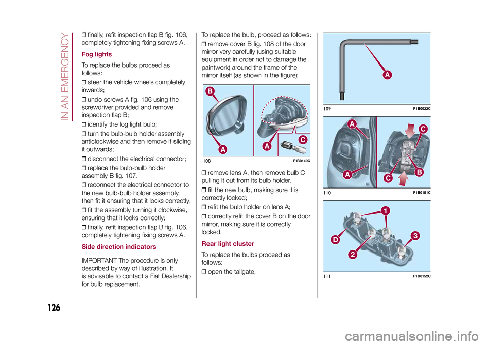
❒remove cover B fig. 108 of the door
mirror very carefully (using suitable
equipment in order not to damage the
paintwork) around the frame of the
mirror itself (as shown in the figure);
❒remove lens A, then remove bulb C
pulling it out from its bulb holder.
❒fit the new bulb, making sure it is
correctly locked;
❒refit the bulb holder on lens A;
❒correctly refit the cover B on the door
mirror, making sure it is correctly
locked.
Rear light clusterTo replace the bulbs proceed as
follows:
❒open the tailgate;108
F1B0149C
109
F1B0022C
110
F1B0151C
111
F1B0152C
126
IN AN EMERGENCY
15-12-2014 8:23 Pagina 126
Page 133 of 240

ENGINE COMPARTMENT FUSE BOXUSERSFUSE AMPEREHornF10 10
Power supply for cigar lighter/power socket F84 20
.
DASHBOARD FUSE BOXUSERSFUSE AMPEREFront electric window (passenger side) F33 20
Front electric window (driver side) F34 20
Supply forUconnect
™
system, Climate Control system, Electric
door mirror folding, EOBD system, USB port/AUX socket, rear
side roof lights (versions with sun roof)F36 15
Dead Lock device (Driver side door unlocking for versions/
markets, where provided)/Door unlocking/Central locking/Electric
tailgate unlockingF38 20
Rear left electric window F47 20
Rear right electric window F48 20
131
15-12-2014 8:23 Pagina 131
Page 166 of 240

❒turn on the battery charger. At the
end of the charging process, switch the
battery charger off;
❒after having disconnected the
charging device, reconnect connector
A to the sensor C as shown.
SERVICING
PROCEDURES
65) 66) 67)
The following pages contain the rules
on therequiredmaintenance
envisaged by the technical personnel
who designed the vehicle.
In addition to these specific
maintenance instructions specified for
routine scheduled servicing, there
are other components which
may require intervention or
replacements over the vehicle’s life
cycle.ENGINE OIL
68)
Engine oil level checkTo ensure correct engine lubrication,
the oil must always be kept at the
prescribed level (see "Engine
compartment" in this chapter).AIR CLEANER
167)
Replacing the air cleanerSee the "Scheduled servicing plan" for
the correct servicing intervals.
It is advisable to replace it with a
genuine spare part, designed especially
for this vehicle.
AIR CONDITIONING
SYSTEM MAINTENANCE
69) 70)
To ensure the best possible
performance, the air conditioning
system must be checked and undergo
maintenance at a Fiat Dealership at
the beginning of the summer.WINDOWSWhen cleaning the heated windscreen
and rear window be careful, if the
defrosting function is active, regarding
the temperature of the glass; also make
sure that children do not come into
contact with the heated surface. The
glass may be hot.
Never use an abrasive detergent to
clean the surface of the windows.
Do not use scrapers or sharp items that
might scratch the windows.
Spray the detergent on the cloth to be
used for cleaning the rear view mirror.
Do not spray the detergent directly
on the glass.
Cleaning the window with hot water
could cause the removal of any labels.
164
SERVICING AND MAINTENANCE
15-12-2014 8:23 Pagina 164