Page 260 of 438

modulate hydraulic pressure, to prevent wheel lock-up
and to help avoid skidding on slippery surfaces.
The system’s pump motor runs during an ABS stop to
provide regulated hydraulic pressure. The pump motor
makes a low humming noise during operation, which is
normal.
The ABS includes an amber ABS Warning Light. When
the light is illuminated, the ABS is not functioning. The
system reverts to standard non-anti-lock brakes. Turning
the ignition Off and On again may reset the ABS if the
fault detected was only momentary.
WARNING!
•Pumping the Anti-Lock Brakes will diminish their
effectiveness and may lead to a collision. Pumping
makes the stopping distance longer. Just press
firmly on your brake pedal when you need to slow
down or stop.
•The Anti-Lock Brake System (ABS) cannot prevent
the natural laws of physics from acting on the
vehicle, nor can it increase braking or steering
efficiency beyond that afforded by the condition of
the vehicle brakes and tires or the traction afforded.
•The ABS cannot prevent collisions, including those
resulting from excessive speed in turns, following
another vehicle too closely, or hydroplaning.
•The capabilities of an ABS-equipped vehicle must
never be exploited in a reckless or dangerous
manner, which could jeopardize the user’s safety or
the safety of others.
258 STARTING AND OPERATING
Page 261 of 438

When you are in a severe braking condition involving the
use of the ABS, you will experience some pedal drop as
the vehicle comes to a stop. This is the result of the
system reverting to the base brake system.
Engagement of the ABS may be accompanied by a
pulsing sensation. You may also hear a clicking noise.
These occurrences are normal and indicate that the
system is functioning properly.
Brake Assist System (BAS)
The BAS is designed to optimize the vehicle’s braking
capability during emergency braking maneuvers. The
system detects an emergency braking situation by sens-
ing the rate and amount of brake application and then
applies optimum pressure to the brakes. This can help
reduce braking distances. The BAS complements the
Anti-Lock Brake System (ABS). Applying the brakes very
quickly results in the best BAS assistance. To receive the
benefit of the system, you must applycontinuousbrak-
ing pressure during the stopping sequence (do not
“pump” the brakes). Do not reduce brake pedal pressure
unless braking is no longer desired. Once the brake pedal
is released, the BAS is deactivated.
WARNING!
•The Brake Assist System (BAS) cannot prevent the
natural laws of physics from acting on the vehicle,
nor can it increase the traction afforded by prevail-
ing road conditions.
•The BAS cannot prevent collisions, including those
resulting from excessive speed in turns, driving on
very slippery surfaces, or hydroplaning.
•The capabilities of a BAS-equipped vehicle must
never be exploited in a reckless or dangerous
manner which could jeopardize the user ’s safety or
the safety of others.
5
STARTING AND OPERATING 259
Page 269 of 438

NOTE:
•P (Passenger) — Metric tire sizing is based on U.S.
design standards. P-Metric tires have the letter “P”
molded into the sidewall preceding the size designa-
tion. Example: P215/65R15 95H.
•European — Metric tire sizing is based on European
design standards. Tires designed to this standard have
the tire size molded into the sidewall beginning with
the section width. The letter#P#is absent from this tire
size designation. Example: 215/65R15 96H.
•LT (Light Truck) — Metric tire sizing is based on U.S.
design standards. The size designation for LT-Metric
tires is the same as for P-Metric tires except for the
letters “LT” that are molded into the sidewall preced-
ing the size designation. Example: LT235/85R16.
•Temporary spare tires are designed for temporary
emergency use only. Temporary high pressure com-
pact spare tires have the letter “T” or “S” molded into
the sidewall preceding the size designation. Example:
T145/80D18 103M.
•High flotation tire sizing is based on U.S. design
standards and it begins with the tire diameter molded
into the sidewall. Example: 31x10.5 R15 LT.5
STARTING AND OPERATING 267
Page 271 of 438

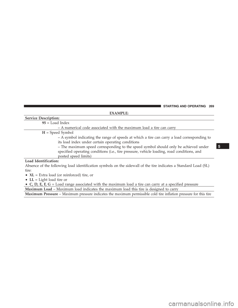
EXAMPLE:
Service Description:
95= Load Index
– A numerical code associated with the maximum load a tire can carry
H= Speed Symbol
– A symbol indicating the range of speeds at which a tire can carry a load corresponding to
its load index under certain operating conditions
– The maximum speed corresponding to the speed symbol should only be achieved under
specified operating conditions (i.e., tire pressure, vehicle loading, road conditions, and
posted speed limits)
Load Identification:
Absence of the following load identification symbols on the sidewall of the tire indicates a Standard Load (SL)
tire:
•XL= Extra load (or reinforced) tire, or
•LL= Light load tire or
•C, D, E, F, G= Load range associated with the maximum load a tire can carry at a specified pressure
Maximum Load– Maximum load indicates the maximum load this tire is designed to carry
Maximum Pressure–Maximum pressure indicates the maximum permissible cold tire inflation pressure for this tire
5
STARTING AND OPERATING 269
Page 320 of 438

WARNING!
•Do not attempt to seal a tire on the side of the
vehicle closest to traffic. Pull far enough off the
road to avoid the danger of being hit when using
the Tire Service Kit.
•Do not use Tire Service Kit or drive the vehicle
under the following circumstances:
– If the puncture in the tire tread is approximately
1/4” (6 mm) or larger.
– If the tire has any sidewall damage.
– If the tire has any damage from driving with
extremely low tire pressure.
– If the tire has any damage from driving on a flat
tire.
– If the wheel has any damage.
– If you are unsure of the condition of the tire or
the wheel.
(Continued)
WARNING!(Continued)
•Keep Tire Service Kit away from open flames or
heat source.
•A loose Tire Service Kit thrown forward in a
collision or hard stop could endanger the occupants
of the vehicle. Always stow the Tire Service Kit in
the place provided. Failure to follow these warn-
ings can result in injuries that are serious or fatal to
you, your passengers, and others around you.
•Take care not to allow the contents of Tire Service
Kit to come in contact with hair, eyes, or clothing.
Tire Service Kit is harmful if inhaled, swallowed,
or absorbed through the skin. It causes skin, eye,
and respiratory irritation. Flush immediately with
plenty of water if there is any contact with eyes or
skin. Change clothing as soon as possible, if there
is any contact with clothing.
(Continued)
318 WHAT TO DO IN EMERGENCIES
Page 358 of 438
The manufacturer recommends that air conditioning
service be performed by authorized dealer using recov-
ery and recycling equipment.
NOTE:Use only manufacturer approved A/C system
PAG compressor oil, and refrigerants.
A/C Air Filter
WARNING!
Do not remove the A/C air filter while the blower is
operating or personal injury may result.
The A/C air filter is located in the fresh air inlet behind
the glove box. Perform the following procedure to re-
place the filter:
1. Open the glove compartment and remove all contents.
2. Push in on the sides of the glove compartment and
lower the door.
3. Pivot the glove compartment downward.
4. Disengage the retaining tabs that secure the air filter
access door to the HVAC housing.
5. Open the air filter access door.
A/C Air Filter Access Door
356 MAINTAINING YOUR VEHICLE
Page 374 of 438

Use only manufacturer’s recommended brake fluid. Re-
fer to “Fluids, Lubricants, and Genuine Parts” in “Main-
taining Your Vehicle” for further information.
WARNING!
•Use only manufacturer’s recommended brake
fluid. Refer to “Fluids, Lubricants, and Genuine
Parts” in “Maintaining Your Vehicle” for further
information. Using the wrong type of brake fluid
can severely damage your brake system and/or
impair its performance. The proper type of brake
fluid for your vehicle is also identified on the
original factory installed hydraulic master cylinder
reservoir.
(Continued)
WARNING!(Continued)
•To avoid contamination from foreign matter or
moisture, use only new brake fluid or fluid that has
been in a tightly closed container. Keep the master
cylinder reservoir cap secured at all times. Brake
fluid in a open container absorbs moisture from the
air resulting in a lower boiling point. This may
cause it to boil unexpectedly during hard or pro-
longed braking, resulting in sudden brake failure.
This could result in a collision.
•Overfilling the brake fluid reservoir can result in
spilling brake fluid on hot engine parts, causing
the brake fluid to catch fire. Brake fluid can also
damage painted and vinyl surfaces, care should be
taken to avoid its contact with these surfaces.
(Continued)
372 MAINTAINING YOUR VEHICLE
Page 387 of 438
Underhood Fuses
The Front Distribution Unit is located on the right side of
the engine compartment, next to the battery. To access the
fuses, press the release tabs and remove the cover.
The ID number of the electrical component correspond-
ing to each fuse can be found on the back of the cover.
Front Distribution Unit
7
MAINTAINING YOUR VEHICLE 385