2015 FIAT 500L LIVING brake
[x] Cancel search: brakePage 111 of 224
HAZARD WARNING
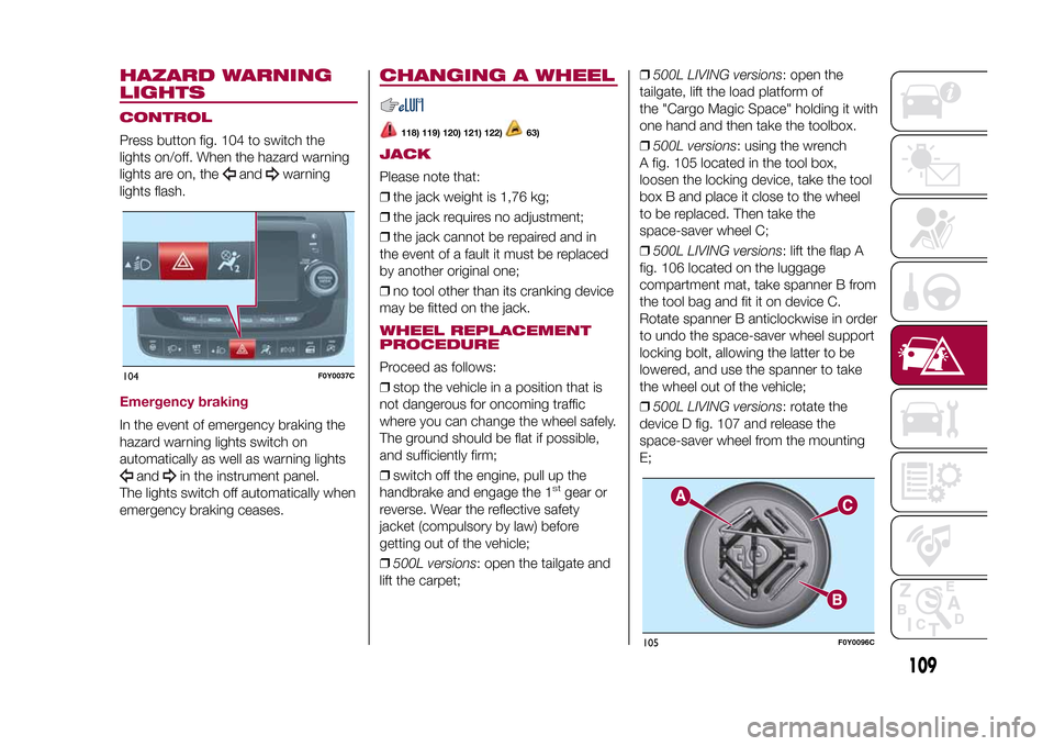
LIGHTSCONTROLPress button fig. 104 to switch the
lights on/off. When the hazard warning
lights are on, the
and
warning
lights flash.
Emergency brakingIn the event of emergency braking the
hazard warning lights switch on
automatically as well as warning lights
and
in the instrument panel.
The lights switch off automatically when
emergency braking ceases.
CHANGING A WHEEL
118) 119) 120) 121) 122)
63)
JACKPlease note that:
❒the jack weight is 1,76 kg;
❒the jack requires no adjustment;
❒the jack cannot be repaired and in
the event of a fault it must be replaced
by another original one;
❒no tool other than its cranking device
may be fitted on the jack.WHEEL REPLACEMENT
PROCEDUREProceed as follows:
❒stop the vehicle in a position that is
not dangerous for oncoming traffic
where you can change the wheel safely.
The ground should be flat if possible,
and sufficiently firm;
❒switch off the engine, pull up the
handbrake and engage the 1
stgear or
reverse. Wear the reflective safety
jacket (compulsory by law) before
getting out of the vehicle;
❒500L versions: open the tailgate and
lift the carpet;❒500L LIVING versions: open the
tailgate, lift the load platform of
the "Cargo Magic Space" holding it with
one hand and then take the toolbox.
❒500L versions: using the wrench
A fig. 105 located in the tool box,
loosen the locking device, take the tool
box B and place it close to the wheel
to be replaced. Then take the
space-saver wheel C;
❒500L LIVING versions: lift the flap A
fig. 106 located on the luggage
compartment mat, take spanner B from
the tool bag and fit it on device C.
Rotate spanner B anticlockwise in order
to undo the space-saver wheel support
locking bolt, allowing the latter to be
lowered, and use the spanner to take
the wheel out of the vehicle;
❒500L LIVING versions: rotate the
device D fig. 107 and release the
space-saver wheel from the mounting
E;
104
F0Y0037C
105
F0Y0096C
109
9-1-2015 12:9 Pagina 109
Page 116 of 224
❒instruction booklet to be used for
prompt and correct use of the kit and
then to be handed to the personnel
charged with handling the treated tyre;
❒a pair of protective gloves located
in the side compartment of the
compressor;
❒adapters for inflating different
elements.
IMPORTANT The sealing fluid is
effective with external temperatures of
between –20°C and +50°C. The sealing
fluid has an expiry date.INFLATION PROCEDUREProceed as follows:
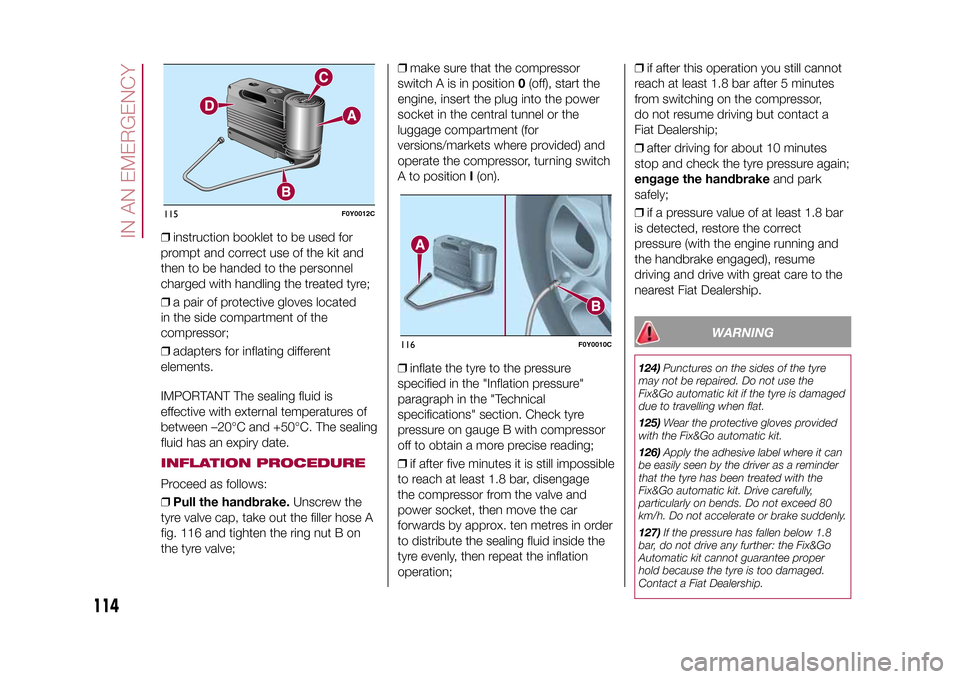
❒Pull the handbrake.Unscrew the
tyre valve cap, take out the filler hose A
fig. 116 and tighten the ring nut B on
the tyre valve;❒make sure that the compressor
switch A is in position0(off), start the
engine, insert the plug into the power
socket in the central tunnel or the
luggage compartment (for
versions/markets where provided) and
operate the compressor, turning switch
A to positionI(on).
❒inflate the tyre to the pressure
specified in the "Inflation pressure"
paragraph in the "Technical
specifications" section. Check tyre
pressure on gauge B with compressor
off to obtain a more precise reading;
❒if after five minutes it is still impossible
to reach at least 1.8 bar, disengage
the compressor from the valve and
power socket, then move the car
forwards by approx. ten metres in order
to distribute the sealing fluid inside the
tyre evenly, then repeat the inflation
operation;❒if after this operation you still cannot
reach at least 1.8 bar after 5 minutes
from switching on the compressor,
do not resume driving but contact a
Fiat Dealership;
❒after driving for about 10 minutes
stop and check the tyre pressure again;
engage the handbrakeand park
safely;
❒if a pressure value of at least 1.8 bar
is detected, restore the correct
pressure (with the engine running and
the handbrake engaged), resume
driving and drive with great care to the
nearest Fiat Dealership.
WARNING
124)Punctures on the sides of the tyre
may not be repaired. Do not use the
Fix&Go automatic kit if the tyre is damaged
due to travelling when flat.
125)Wear the protective gloves provided
with the Fix&Go automatic kit.
126)Apply the adhesive label where it can
be easily seen by the driver as a reminder
that the tyre has been treated with the
Fix&Go automatic kit. Drive carefully,
particularly on bends. Do not exceed 80
km/h. Do not accelerate or brake suddenly.
127)If the pressure has fallen below 1.8
bar, do not drive any further: the Fix&Go
Automatic kit cannot guarantee proper
hold because the tyre is too damaged.
Contact a Fiat Dealership.
115
F0Y0012C
116
F0Y0010C
114
IN AN EMERGENCY
9-1-2015 12:9 Pagina 114
Page 119 of 224
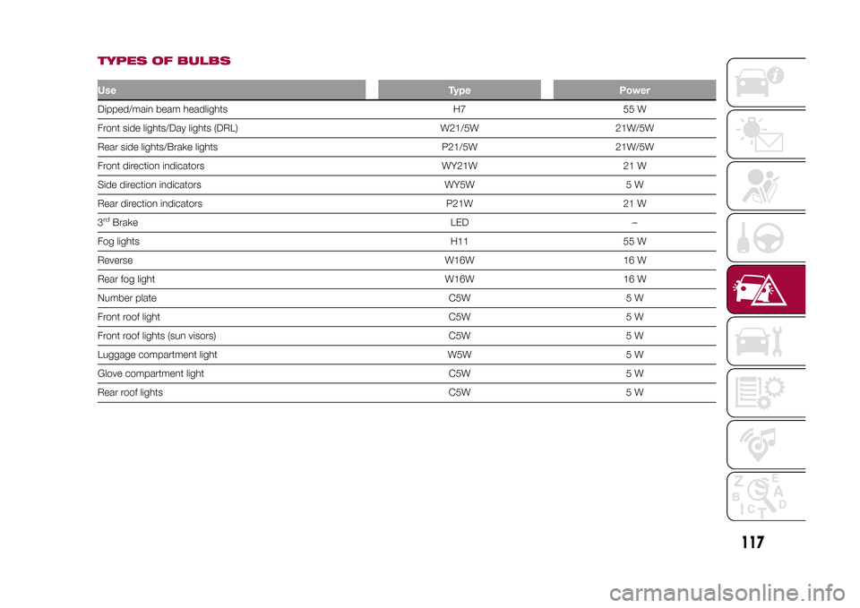
TYPES OF BULBSUseType PowerDipped/main beam headlights H7 55 W
Front side lights/Day lights (DRL) W21/5W 21W/5W
Rear side lights/Brake lights P21/5W 21W/5W
Front direction indicators WY21W 21 W
Side direction indicators WY5W 5 W
Rear direction indicators P21W 21 W
3rdBrake LED –
Fog lights H11 55 W
Reverse W16W 16 W
Rear fog light W16W 16 W
Number plate C5W 5 W
Front roof light C5W 5 W
Front roof lights (sun visors) C5W 5 W
Luggage compartment light W5W 5 W
Glove compartment light C5W 5 W
Rear roof lights C5W 5 W
117
9-1-2015 12:9 Pagina 117
Page 122 of 224
❒refit the cluster making sure that the
internal catch B fig. 125 clips into
position.FOG LIGHTS(for versions/markets, where provided)
To replace the bulb, proceed as follows:
❒steer the wheel completely inwards;
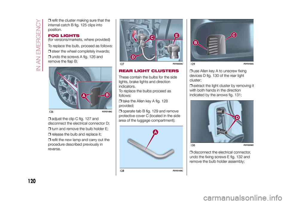
❒undo the screws A fig. 126 and
remove the flap B;
❒adjust the clip C fig. 127 and
disconnect the electrical connector D;
❒turn and remove the bulb holder E;
❒release the bulb and replace it;
❒refit the new lamp and carry out the
procedure described previously in
reverse.
REAR LIGHT CLUSTERSThese contain the bulbs for the side
lights, brake lights and direction
indicators.
To replace the bulbs proceed as
follows:
❒take the Allen key A fig. 128
provided;
❒operate tab B fig. 129 and remove
protective cover C (located in the side
area of the luggage compartment);❒use Allen key A to unscrew fixing
devices D fig. 130 of the rear light
cluster;
❒extract the light cluster by removing it
with both hands in the direction
indicated by the arrows fig. 131;
❒disconnect the electrical connector,
undo the fixing screws E fig. 132 and
remove the bulb holder assembly;
126
F0Y0148C
127
F0Y0033C
128
F0Y0149C
129
F0Y0150C
130
F0Y0258C
120
IN AN EMERGENCY
9-1-2015 12:9 Pagina 120
Page 123 of 224
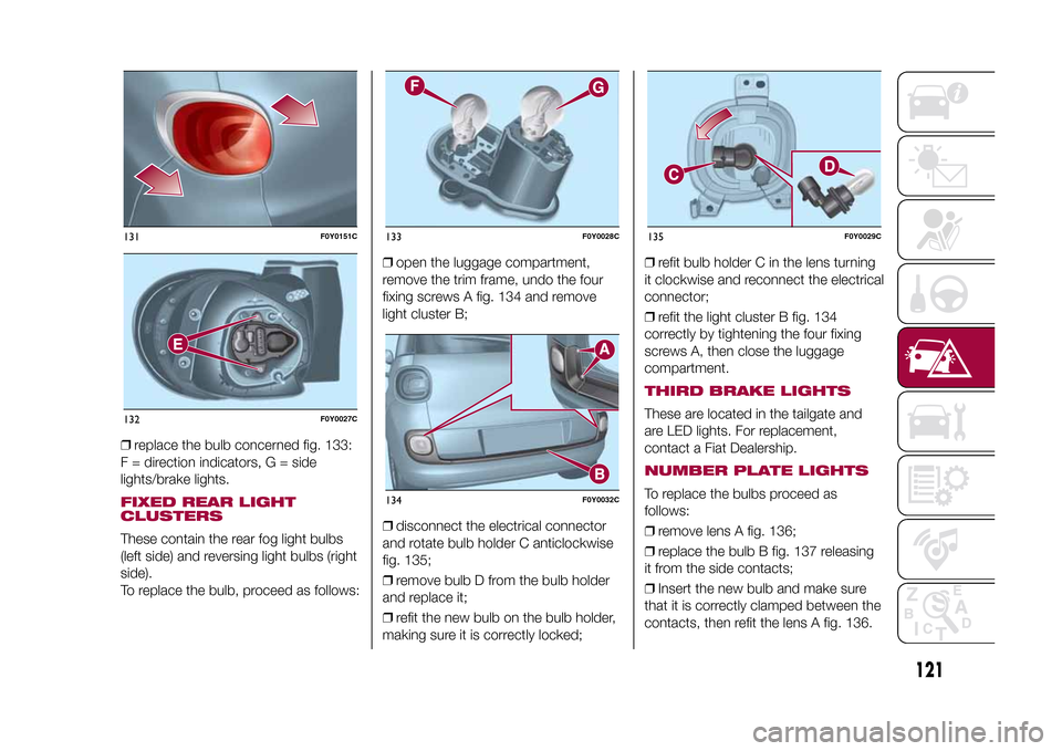
❒replace the bulb concerned fig. 133:
F = direction indicators, G = side
lights/brake lights.FIXED REAR LIGHT
CLUSTERSThese contain the rear fog light bulbs
(left side) and reversing light bulbs (right
side).
To replace the bulb, proceed as follows:❒open the luggage compartment,
remove the trim frame, undo the four
fixing screws A fig. 134 and remove
light cluster B;
❒disconnect the electrical connector
and rotate bulb holder C anticlockwise
fig. 135;
❒remove bulb D from the bulb holder
and replace it;
❒refit the new bulb on the bulb holder,
making sure it is correctly locked;❒refit bulb holder C in the lens turning
it clockwise and reconnect the electrical
connector;
❒refit the light cluster B fig. 134
correctly by tightening the four fixing
screws A, then close the luggage
compartment.
THIRD BRAKE LIGHTSThese are located in the tailgate and
are LED lights. For replacement,
contact a Fiat Dealership.NUMBER PLATE LIGHTSTo replace the bulbs proceed as
follows:
❒remove lens A fig. 136;
❒replace the bulb B fig. 137 releasing
it from the side contacts;
❒Insert the new bulb and make sure
that it is correctly clamped between the
contacts, then refit the lens A fig. 136.
131
F0Y0151C
132
F0Y0027C
133
F0Y0028C
134
F0Y0032C
135
F0Y0029C
121
9-1-2015 12:9 Pagina 121
Page 130 of 224
JUMP STARTINGIf the battery is flat, a jump starting can
be performed using the battery and
the cables of another vehicle, or using a
booster battery.IMPORTANTWhen a booster battery is used, comply
with the utilisation and precaution
instructions specified by the producer.
Do not use the booster battery or
any other source of external supply with
a voltage above 12 V: the battery, the
starter, the alternator and the electrical
system of the vehicle could be
damaged.
Do not attempt jump starting if the
battery is frozen. The battery could
break and explode!PREPARATION TO JUMP
STARTING
140) 141) 142)
68)
IMPORTANT The positive terminal (+) of
the battery is shielded by a protective
cover. Lift the cover to access the
positive terminal.
Proceed as follows:
❒engage the handbrake, move the
Dualogic gear lever to P (Park) or,
for versions with manual gearbox, to
neutral and bring the ignition key to
STOP;❒switch off all the other electrical
devices in the vehicle;
❒if another vehicle is ready for jump
starting, park the vehicle within the
reach of the cables to be used for
starting, operate the handbrake and
make sure that the ignition is
deactivated.
IMPORTANT Avoid contact between
the two vehicles since this could cause
a connection to earth and may result
in serious injury to any people nearby.
PROCEDURE FOR JUMP
STARTINGIMPORTANT If the procedure below is
carried out incorrectly, it can cause
severe injury to people or damage the
recharging system of one or both
vehicles. Carefully follow the
instructions given below.Cable connectionProceed as follows to carry out a jump
starting:
❒connect one end of the cable used
for positive (+) to the positive terminal
(+) of the vehicle with flat battery;
❒connect the other end of the cable
used for positive (+) to the positive
terminal (+) of the auxiliary battery;❒connect one end of the cable used
for negative (–) to the negative terminal
(–) of the auxiliary battery;
❒connect the other end of the cable
used for negative (–) to an engine earth
(the visible metal part of the vehicle
engine with flat battery) away from the
battery and the fuel injection system;
❒start the vehicle engine with the
auxiliary battery, let it run for a
few minutes at idling. Start the engine
of the vehicle with flat battery.
Cable disconnectionOnce the engine has been started,
remove the cables proceeding as
follows:
❒disconnect the end of the cable used
for negative (–) from the engine earth
of the vehicle with flat battery;
❒disconnect the other end of the cable
used for negative (–) from the negative
terminal (–) of the auxiliary battery;
❒disconnect the end of the cable used
for positive (+) from the positive terminal
(+) of the auxiliary battery;
❒disconnect one end of the cable
used for positive (+) from the positive
terminal (+) of the vehicle with flat
battery.
128
IN AN EMERGENCY
9-1-2015 12:9 Pagina 128
Page 133 of 224
146)Whilst towing, remember that the
assistance of the brake servo and the
electric power steering is not available,
therefore greater force needs to be exerted
on the brake pedal and more effort is
required on the steering wheel. Do not use
flexible cables when towing and avoid
jerky movements. Make sure not to
damage parts in contact with the car while
towing. When towing the car, you must
comply with all specific traffic regulations,
both in terms of the towing device and
behaviour on the road. Do not start the
engine while being towed.
147)The front and rear tow hooks should
be used only for emergencies on the road.
The car may be towed for short distances
when a dedicated device is used in
compliance with the Highway Code (rigid
bar), and in order to move the vehicle
on the road in preparation for towing or
transport via a tow truck (on the Trekking
versions do NOT use the rear tow hook for
transport on a tow truck: use the front
tow hook). Tow hooks MUST NOT be used
to tow vehicles off the road or where there
are obstacles and/or for towing operations
using ropes or other non-rigid devices.
Respecting the above conditions, towing
must take place with two vehicles (one
towing, the other towed) aligned as much
as possible along the same centre line.
131
9-1-2015 12:9 Pagina 131
Page 135 of 224
SCHEDULED
SERVICINGCorrect servicing is crucial for
guaranteeing a long life for the vehicle
under the best conditions. For this
reason, Fiat has planned a series of
checks and services at fixed distance
intervals and, where provided, at fixed
time intervals, as described in the
Scheduled Servicing Plan.
Before each service, it is always
necessary to carefully follow the
instructions in the Scheduled Servicing
Plan (e.g. periodically check level of
fluids, tyre pressure, etc.).
Scheduled Servicing is offered by all
Fiat Dealerships according to a set time
schedule. If, during each operation, in
addition to the ones scheduled, the
need arises for further replacements or
repairs, these may be carried out with
the owner's explicit agreement only.
If your vehicle is used frequently for
towing, the interval between one
service operation and the next should
be reduced.IMPORTANT Scheduled Servicing
interventions are set out by the
Manufacturer. Failure to have them
carried out may invalidate the warranty.
It is advisable to inform a Fiat
Dealership of any small operating
irregularities without waiting for the next
service.
PERIODIC CHECKSEvery1,000km or before long
journeys, check and if necessary, top
up: engine coolant level; brake fluid
level; screen washer fluid level; tyre
inflation pressure and condition; lighting
system operation (headlights, direction
indicators, hazard warning lights, etc.);
screen washer/wiper system operation
and positioning/wear of windscreen/
rear window wiper blades.
Every3,000km, check and top up if
required: engine oil level.HEAVY-DUTY USE OF THE
VEHICLEIf the vehicle is used under one of the
following conditions:
❒towing a trailer or caravan;
❒dusty roads;
❒short, repeated journeys (less than
7-8 km) at sub-zero outside
temperatures;❒engine often idling or driving long
distances at low speeds or long periods
of inactivity;
the following checks must be carried
out more often than indicated in the
Scheduled Servicing Plan:
❒check front disc brake pad condition
and wear;
❒check cleanliness of bonnet and
luggage compartment locks,
cleanliness and lubrication of linkage;
❒visually inspect conditions of: engine,
gearbox, transmission, pipes and
hoses (exhaust/fuel system/brakes) and
rubber elements (gaiters/sleeves/
bushes, etc.);
❒check battery charge and battery
fluid level (electrolyte);
❒visually inspect conditions of the
accessory drive belts;
❒check and, if necessary, change
engine oil and replace oil filter;
❒check and, if necessary, replace
pollen filter;
❒check and, if necessary, replace air
cleaner.
133
9-1-2015 12:9 Pagina 133