2015 FIAT 500L LIVING tow
[x] Cancel search: towPage 98 of 224
WARNING
104)Depress the clutch pedal fully to
change gear correctly. Therefore, the floor
area underneath the pedal unit must not
be obstructed in any way. Ensure that the
floor mat is always laid flat and does not
interfere with use of the pedals.
WARNING
56)Do not drive with your hand resting on
the gear lever as the force exerted, even
if slight, could lead over time to premature
wear of the gearbox internal components.
USING THE
DUALOGIC
GEARBOX(for versions/markets, where provided)
105)
57)
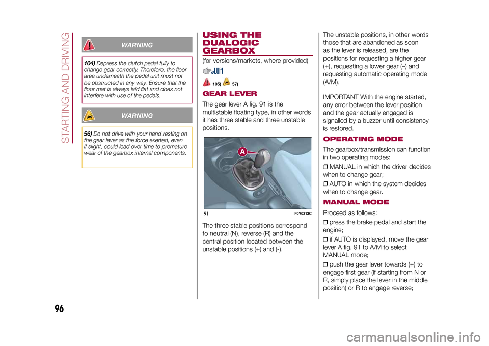
GEAR LEVERThe gear lever A fig. 91 is the
multistable floating type, in other words
it has three stable and three unstable
positions.
The three stable positions correspond
to neutral (N), reverse (R) and the
central position located between the
unstable positions (+) and (-).The unstable positions, in other words
those that are abandoned as soon
as the lever is released, are the
positions for requesting a higher gear
(+), requesting a lower gear (–) and
requesting automatic operating mode
(A/M).
IMPORTANT With the engine started,
any error between the lever position
and the gear actually engaged is
signalled by a buzzer until consistency
is restored.
OPERATING MODEThe gearbox/transmission can function
in two operating modes:
❒MANUAL in which the driver decides
when to change gear;
❒AUTO in which the system decides
when to change gear.MANUAL MODEProceed as follows:
❒press the brake pedal and start the
engine;
❒if AUTO is displayed, move the gear
lever A fig. 91 to A/M to select
MANUAL mode;
❒push the gear lever towards (+) to
engage first gear (if starting from N or
R, simply place the lever in the middle
position) or R to engage reverse;
91
F0Y0313C
96
STARTING AND DRIVING
9-1-2015 12:9 Pagina 96
Page 99 of 224
❒release the brake pedal and press
the accelerator pedal;
❒in driving conditions, push the gear
lever towards (+) to engage the next
gear up or towards (–) to engage the
next gear down.AUTOMATIC LOGIC
(AUTO)Proceed as follows:
❒press the brake pedal and start the
engine;
❒if AUTO is not displayed, move the
gear lever A fig. 91 to A/M to select
AUTOMATIC mode;
❒push the gear lever towards (+) to
engage first gear (if starting from N or
R, simply place the lever in the middle
position), or R to engage reverse;
❒release the brake pedal and press
the accelerator pedal: the gear most
suited to the vehicle speed will be
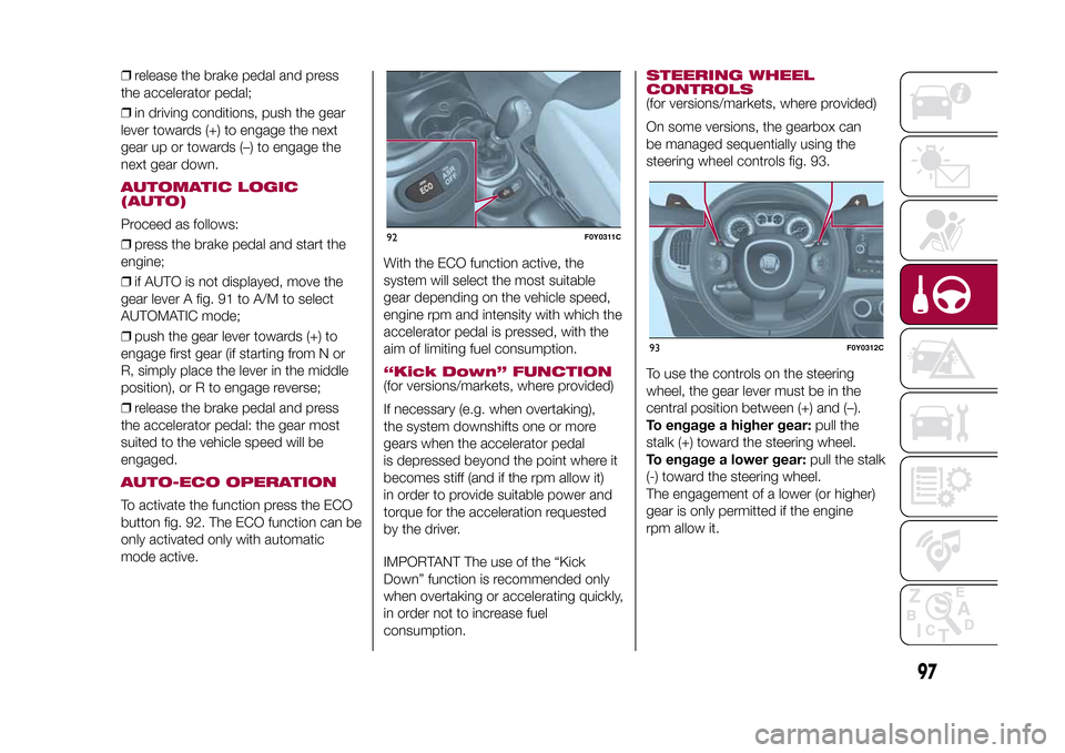
engaged.AUTO-ECO OPERATIONTo activate the function press the ECO
button fig. 92. The ECO function can be
only activated only with automatic
mode active.With the ECO function active, the
system will select the most suitable
gear depending on the vehicle speed,
engine rpm and intensity with which the
accelerator pedal is pressed, with the
aim of limiting fuel consumption.
“Kick Down” FUNCTION(for versions/markets, where provided)
If necessary (e.g. when overtaking),
the system downshifts one or more
gears when the accelerator pedal
is depressed beyond the point where it
becomes stiff (and if the rpm allow it)
in order to provide suitable power and
torque for the acceleration requested
by the driver.
IMPORTANT The use of the “Kick
Down” function is recommended only
when overtaking or accelerating quickly,
in order not to increase fuel
consumption.
STEERING WHEEL
CONTROLS(for versions/markets, where provided)
On some versions, the gearbox can
be managed sequentially using the
steering wheel controls fig. 93.
To use the controls on the steering
wheel, the gear lever must be in the
central position between (+) and (–).
To engage a higher gear:pull the
stalk (+) toward the steering wheel.
To engage a lower gear:pull the stalk
(-) toward the steering wheel.
The engagement of a lower (or higher)
gear is only permitted if the engine
rpm allow it.
92
F0Y0311C
93
F0Y0312C
97
9-1-2015 12:9 Pagina 97
Page 101 of 224
107)Before opening the bonnet, make
sure that the engine is off and that the
ignition key is in the STOP position. Always
refer to the plate inside the bonnet. We
recommend that you remove the key from
the ignition if other people remain in the
vehicle. Exit from the car only after having
removed the ignition key or having rotated
it to the STOP position. During refuelling,
make sure that the engine is off and that
the ignition key is in the STOP position.
WARNING
58)If climate comfort is to be favoured, the
Stop/Start system can be disabled, for a
continuous operation of the climate control
system.
CRUISE CONTROL
(constant speed
regulator)(for versions/markets, where provided)
108) 109)
DESCRIPTIONThis is an electronically controlled
driving assistance device that allows
the desired car speed to be maintained,
without having to press the accelerator
pedal.
This device can be used at a speed
above 30 km/h on long stretches of dry,
straight roads with few variations (e.g.
motorways).
The use of this device on extra-urban
roads with traffic is not therefore
recommended. Do not use the device
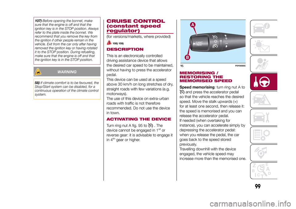
in town.ACTIVATING THE DEVICETurn ring nut A fig. 95 to
. The
device cannot be engaged in 1
stor
reverse gear: it is advisable to engage it
in 4
th
gear or higher.
MEMORISING /
RESTORING THE
MEMORISED SPEEDSpeed memorising: turn ring nut A to
and press the accelerator pedal
so that the vehicle reaches the desired
speed. Move the stalk upwards (+)
for at least one second, then release it:
the speed is memorised and you can
release the accelerator pedal.
If needed (when overtaking for
instance), you can accelerate simply by
depressing the accelerator pedal:
when you release the pedal, the car
goes back to the speed stored
previously.
Travelling downhill with the device
engaged, the vehicle speed may
increase more than the memorised one.
95
F0Y0050C
99
9-1-2015 12:9 Pagina 99
Page 104 of 224
OPERATION WITH A
TRAILERSensor operation is deactivated
automatically when the trailer's electric
cable plug is fitted into the car's tow
hook socket.
The sensors are automatically
reactivated when the trailer's cable plug
is removed.IMPORTANT
INFORMATIONWhen parking, take the utmost care
over obstacles that may be above
or below the sensors.
Under certain circumstances, objects
close to the vehicle are not detected by
the system and could therefore cause
damage to the car or be damaged
themselves.
Some conditions may influence the
performance of the parking sensors:
❒the presence of ice, snow, mud
or think paint on the sensor surface
may cause reduced sensitivity of the
sensor itself and therefore reduce
the system performance.
❒mechanical interference (e.g. washing
the car, rain, strong wind, hail) may
cause the sensor to detect a
non-existent obstacle ("echo
interference");❒the presence of ultrasonic systems
(e.g. pneumatic brake systems of
trucks or pneumatic drills) near the car
could alter the signals sent by the
sensor;
❒the variation in sensor position,
caused by variation in ride (due
to suspension component wear),
changing tyres, overloaded car, or
tuning that lowers the car, for example,
may affect parking sensor system
performance.
WARNING
110)Parking and other dangerous
manoeuvres are, however, always the
driver’s responsibility. While carrying out
these manoeuvres, always make sure that
no people (especially children) or animals
are in the area concerned. The parking
sensors are an aid for the driver, but the
driver must never allow their attention
to lapse during potentially dangerous
manoeuvres, even those executed at low
speeds.
WARNING
59)The sensors must be free from mud,
dirt, snow or ice in order for the system to
operate correctly. Be careful not to scratch
or damage the sensors while cleaning
them. Avoid using dry, rough or hard
cloths. The sensors should be washed
using clean water with the addition of car
shampoo if necessary. When using special
washing equipment such as high pressure
jets or steam cleaning, clean the sensors
very quickly keeping the jet more than
10 cm away. Also, do not apply stickers to
the sensors.
102
STARTING AND DRIVING
9-1-2015 12:9 Pagina 102
Page 106 of 224
WARNING
60)It is extremely important, for correct
operation, that the camera is always kept
clean and free from mud, dirt, snow or ice.
Be careful not to scratch or damage the
camera while cleaning it. Avoid using
dry, rough or hard cloths. The camera
must be washed using clean water, with
the addition of car shampoo if necessary.
In washing stations which use steam or
high-pressure jets, clean the camera
quickly, keeping the nozzle more than 10
cm away. Do not apply stickers to the
camera.
TOWING TRAILERS
112) 113) 114)
INSTALLING A TOW
HOOKThe towing device should be fastened
to the body by specialised personnel
according to any additional and/or
integrative information supplied by the
Manufacturer of the device.
The towing device must meet current
regulations with reference to Directive
94/20/EC and subsequent
amendments.
For any version the towing device used
must be right for the towable weight
of the vehicle on which it is to be
installed.
For the electrical connection a standard
connector should be used which is
generally placed on a special bracket
normally fastened to the towing device,
and a special ECU for external trailer
light control must be installed on the
vehicle.
Seven or thirteen pin 12 V DC
connections should be used (CUNA/
UNI and ISO/DIN Standards). Follow
any instructions provided by the vehicle
manufacturer and/or the towing device
manufacturer.
IMPORTANTFor towing caravans or trailers the car
must be fitted with a type-approved
tow hook and an adequate electrical
system. Installation must be carried out
by a specialist.
Install any specific and/or additional
rear view mirrors as specified by the
Highway Code.
Remember that when towing a trailer,
steep hills are harder to climb, braking
distances increase and overtaking
takes longer depending on the overall
weight of the trail.
Engage a low gear when driving
downhill, rather than constantly using
the brake.
The weight of the trailer on the car's
tow hook will reduce the load capacity
of the car by the same amount. To
make sure that the maximum towable
weight is not exceeded (given in the car
registration document) account should
be taken of the fully laden trailer,
including accessories and luggage.
Respect the speed limits specific to
each country for vehicles towing
trailers. In any case, the top speed
must not exceed 100 km/h.
Any electric brake or other device
(winch etc.) should be powered directly
by the battery through a cable with a
cross-section of no less than 2.5 mm
2.
104
STARTING AND DRIVING
9-1-2015 12:9 Pagina 104
Page 107 of 224
In addition to the electrical branches,
the car's electrical system can be
connected only to the supply cable for
an electric brake and to the cable for an
internal trailer light, though not more
than 15 W. To connect, use the preset
control unit with a battery cable with
cross-section no less than 2.5 mm
2.
IMPORTANT The use of auxiliary loads
other than external lights (electric brake,
winch, etc.) must occur with engine
running.
IMPORTANT To install a tow hook
contact a Fiat Dealership.
WARNING
112)The ABS with which the vehicle is
equipped will not control the braking
system of the trailer. Take particular care
when travelling on slippery roads.
113)Never modify the braking system of
the vehicle to control the trailer brake. The
trailer braking system must be fully
independent of the vehicle’s hydraulic
system.
114)After fitting, fixing screw holes must
be sealed to prevent an exhaust gas inlet.
REFUELLING THE
VEHICLE
115) 116) 117)
61)
During refuelling, switch the engine off,
engage the handbrake, turn the ignition
key to STOP and do not smoke.PETROL ENGINESUse unleaded petrol only, with octane
number (RON) no lower than 95.DIESEL ENGINESOnly use Diesel for motor vehicles (EN
590 specification).
When using or parking the car for a
long time in the mountains or cold
areas, it is advisable to refuel using
locally available diesel. In this case, it is
also advisable to keep the tank over
50% full.REFUELLING
PROCEDURE
Diesel and petrol versionsProceed as follows:
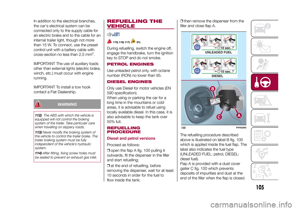
❒open the flap A fig. 100 pulling it
outwards, fit the dispenser in the filler
and start refuelling;
❒at the end of refuelling, before
removing the dispenser, wait for at least
10 seconds in order for the fuel to
flow inside the tank;❒then remove the dispenser from the
filler and close flap A.
The refuelling procedure described
above is illustrated on label B fig. 100
which is applied inside the fuel flap. The
label also indicates the fuel type
(UNLEADED FUEL: petrol, DIESEL:
diesel fuel).
Flap A is provided with a dust cover
gaiter C fig. 100 which prevents
deposits of impurities and dust at the
end of the filler when the flap is closed.
100
F0Y0229C
105
9-1-2015 12:9 Pagina 105
Page 110 of 224
IN AN EMERGENCY
A punctured tyre or a burnt-out bulb?
At times, a problem may interfere
with our journey.
The pages on emergencies can help
you to deal with critical situations
independently and with calm.
In an emergency we recommend that
you call the freephone number found in
the Warranty Booklet.
It is also possible to call the national or
international universal freephone
number to search for the nearest
Dealership.HAZARD WARNING LIGHTS...........109
CHANGING A WHEEL ....................109
"FIX&GO AUTOMATIC" KIT .............113
REPLACING A BULB ......................115
REPLACING FUSES........................122
JUMP STARTING ............................128
FUEL CUT-OFF SYSTEM ................129
TOWING THE VEHICLE ..................130
108
IN AN EMERGENCY
9-1-2015 12:9 Pagina 108
Page 114 of 224
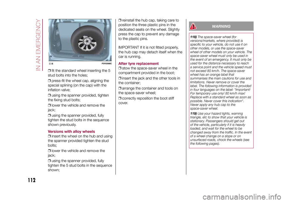
❒fit the standard wheel inserting the 5
stud bolts into the holes;
❒press-fit the wheel cap, aligning the
special splining (on the cap) with the
inflation valve;
❒using the spanner provided, tighten
the fixing stud bolts;
❒lower the vehicle and remove the
jack;
❒using the spanner provided, fully
tighten the stud bolts in the sequence
shown previously.Versions with alloy wheels❒insert the wheel on the hub and using
the spanner provided tighten the stud
bolts;
❒lower the vehicle and remove the
jack;
❒using the spanner provided, fully
tighten the 5 stud bolts in the sequence
shown;❒reinstall the hub cap, taking care to
position the three plastic pins in the
dedicated seats on the wheel. Slightly
press the cap to prevent any damage
to the plastic pins.
IMPORTANT If it is not fitted properly,
the hub cap may detach itself when the
car is running.
After tyre replacement❒stow the space-saver wheel in the
compartment provided in the boot;
❒insert the jack and the other tools in
the container;
❒arrange the container and tools on
the space-saver wheel;
❒correctly reposition the boot stiff
cover.
WARNING
118)The space-saver wheel (for
versions/markets, where provided) is
specific to your vehicle, do not use it on
other models, or use the space-saver
wheel of other models on your vehicle. The
space-saver wheel must only be used in
the event of an emergency. It must only be
used for the distance necessary to reach
a service point and the vehicle speed must
not exceed 80 km/h. The space-saver
wheel has an orange label that
summarises the main cautions for use and
limitations. Never remove or cover the
label. The following information is provided
in four languages on the label: "Important!
For temporary use only! 80 km/h max!
Replace with a standard wheel as soon as
possible. Never cover this indication".
Never apply any hub cap to the
space-saver wheel.
119)Use your hazard lights, warning
triangle, etc to show that your vehicle is
stationary. Passengers should get out
of the vehicle, particularly if it is heavily
loaded, and wait for the wheel to be
changed away from the traffic. In the event
of a wheel change on a slope or on
unsurfaced roads, chock the wheels (see
the following pages).
114
F0Y0368C
112
IN AN EMERGENCY
9-1-2015 12:9 Pagina 112