2015 DODGE GRAND CARAVAN clock
[x] Cancel search: clockPage 16 of 164

Removing The Button
•TheENGINESTART/STOPbuttoncan
be removed from the ignition switch for
Key Fob use.
•Insertthemetalpartoftheemergency
key under the chrome bezel at the 6
o’clock position and gently pry the button
loose.
NOTE:
The ENGINE START/STOP button should
only be removed or inserted with the igni-
tion in the LOCK position (OFF position for
Keyless Enter-N-Go™).
Engine Starting/Stopping
Starting
Perform the following starting procedure with a Remote Keyless Entry (RKE) transmitter
inside the vehicle:
1. Place the shift lever in PARK or NEUTRAL.
2. While pushing the brake pedal, push the ENGINE START/STOP button once. If the
engine fails to start, the starter will disengage automatically after 10 seconds.
3. To stop the cranking of the engine prior to the engine starting, push the button again.
Stopping
1. Bring the vehicle to a complete stop.
2. Shift the transmission to PARK (P).
3. Push the ENGINE START/STOP button once. The ignition switch will return to the OFF
position.
NOTE:
If the transmission is not in PARK and the vehicle is in motion, the ENGINE START/
STOP button must be held for two seconds with the vehicle speed above 5 mph
(8 km/h) before the engine will shut off.
Removing START/STOP Button
GETTING STARTED
14
Page 60 of 164

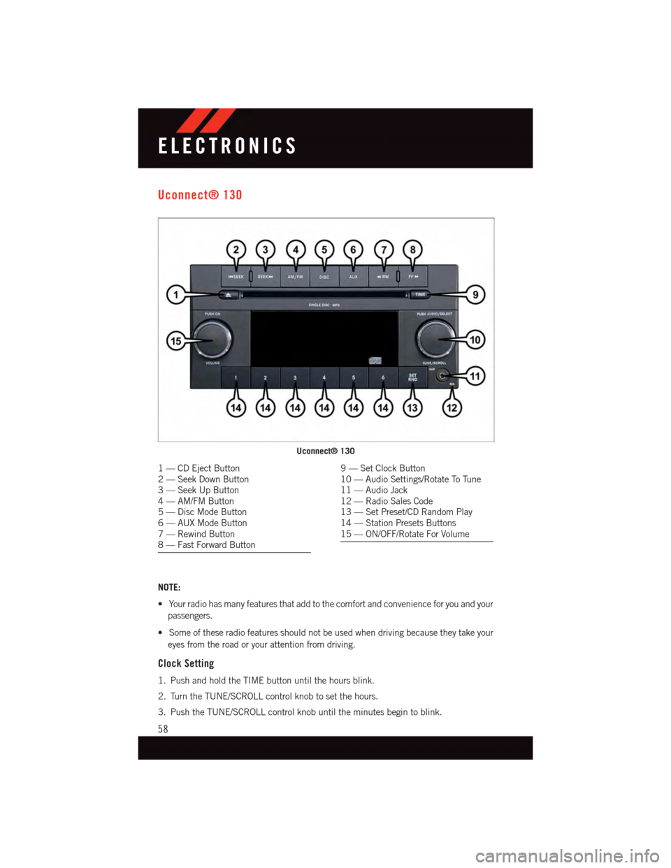
Uconnect® 130
NOTE:
•Yourradiohasmanyfeaturesthataddtothecomfortandconvenienceforyouandyour
passengers.
•Someoftheseradiofeaturesshouldnotbeusedwhendrivingbecausetheytakeyour
eyes from the road or your attention from driving.
Clock Setting
1. Push and hold the TIME button until the hours blink.
2. Turn the TUNE/SCROLL control knob to set the hours.
3. Push the TUNE/SCROLL control knob until the minutes begin to blink.
Uconnect® 130
1—CDEjectButton2—SeekDownButton3—SeekUpButton4—AM/FMButton5—DiscModeButton6—AUXModeButton7—RewindButton8—FastForwardButton
9—SetClockButton10 — Audio Settings/Rotate To Tune11 — Audio Jack12 — Radio Sales Code13 — Set Preset/CD Random Play14 — Station Presets Buttons15 — ON/OFF/Rotate For Volume
ELECTRONICS
58
Page 62 of 164

Uconnect® 130 WITH SiriusXM SATELLITE RADIO
NOTE:
•YourradiomaynotbeequippedwiththeUconnect®Voice Command and Uconnect®
Phone features. To determine if your radio has these features, push the Voice Command
button on the radio. You will hear a voice prompt if you have the feature, or see a
message on the radio stating “Uconnect Phone not available” if you do not.
•Yourradiohasmanyfeaturesthataddtothecomfortandconvenienceofyouandyour
passengers. Some of these radio features should not be used when driving because they
take your eyes from the road or your attention from driving.
Uconnect® 130 With SiriusXM Satellite Radio
1—CDEjectButton2—SeekDownButton3—SeekUpButton4—VoiceCommandButton5—Uconnect®Phone Button6—StationInfoButton7—RewindButton8—FastForwardButton9—SetClockButton10 — Audio Settings/Rotate To Tune11 — Audio Jack
12 — Radio Sales Code13 — Set Preset/CD Random Play14 — Station Preset Buttons15 — ON/OFF/Rotate For Volume16 — AM/FM Mode Button17 — List Folders On A CD18 — Satellite Radio Button19 — Music Type Button20 — Disc Mode Button21 — Set Up Function Button
ELECTRONICS
60
Page 63 of 164

Clock Setting
1. Push and hold the TIME button until the hours blink.
2. Turn the TUNE/SCROLL control knob to set the hours.
3. Push the TUNE/SCROLL control knob until the minutes begin to blink.
4. Turn the TUNE/SCROLL control knob to set the minutes.
5. Push the TUNE/SCROLL control knob to save the changes.
6. Push any button/knob or wait five seconds to exit.
Equalizer, Balance And Fade
1. Push the TUNE/SCROLL control knob and “BASS” will display.
2. Rotate the TUNE/SCROLL control knob to select the desired setting.
3. Continue pushing the TUNE/SCROLL control knob to display and set “MID RANGE,”
“TREBLE,” “BALANCE” and “FADE.”
Radio Operation
Seek Up/Down Buttons
•PushtoseekthroughradiostationsinAM,FM,orSATbands.
•Holdeitherbuttontobypassstationswithoutstopping.
Store Radio Presets
•PushtheSET/RNDorSET(dependingontheradio)buttononceandSET1willshow
in the display. Then select a preset button (1–6).
•Asecondstationmaybeaddedtoeachpushbutton.PushtheSET/RNDorSET
(depending on the radio) button twice and SET 2 will show in the display. Then select
apresetbutton(1–6).
Music Type
NOTE:
The Music Type function only operates when in FM mode.
•PushtheMUSICTYPEbuttontoactivatethismode.PushtheMUSICTYPEbutton
again or turn the TUNE/SCROLL control knob to select the desired music type (Adult
Hits, Country, Jazz, Oldies, Rock, etc.).
•WhenamusictypeischosenandtheMusictypeisdisplayed,PusheitherSEEKbutton
and the radio will only search for stations with the selected music type.
SETUP Button
•PushingtheSETUPbuttonallowsyoutoselectbetweenitemsthatareavailableinthat
particular mode.
•TurntheTUNE/SCROLLcontrolknobtoscrollthroughtheentries.PushtheAUDIO/
SELECT button to select an entry and make changes.
ELECTRONICS
61
Page 66 of 164

Clock Setting
1. Turn the radio on, then press the screen where the time is displayed.
2. Press the “User Clock” button on the touchscreen or the time display (Navigation radio
only).
3. To adjust the hours, press either the “Hour Forward” or “Hour Backward” button on the
touchscreen.
4. To adjust the minutes, press either the “Minute Forward” or “Minute Backward”
button on the touchscreen.
5. To save the new time setting, press the screen where the word “Save” is displayed.
Menu
•PushtheMENUbuttononthefaceplatetoaccesstheSystemSetupmenuandtheMy
Files menu.
•PushtheMENUbuttononthefaceplateinanactivemode(SAT,CD,AUX,etc.)to
change mode specific settings.
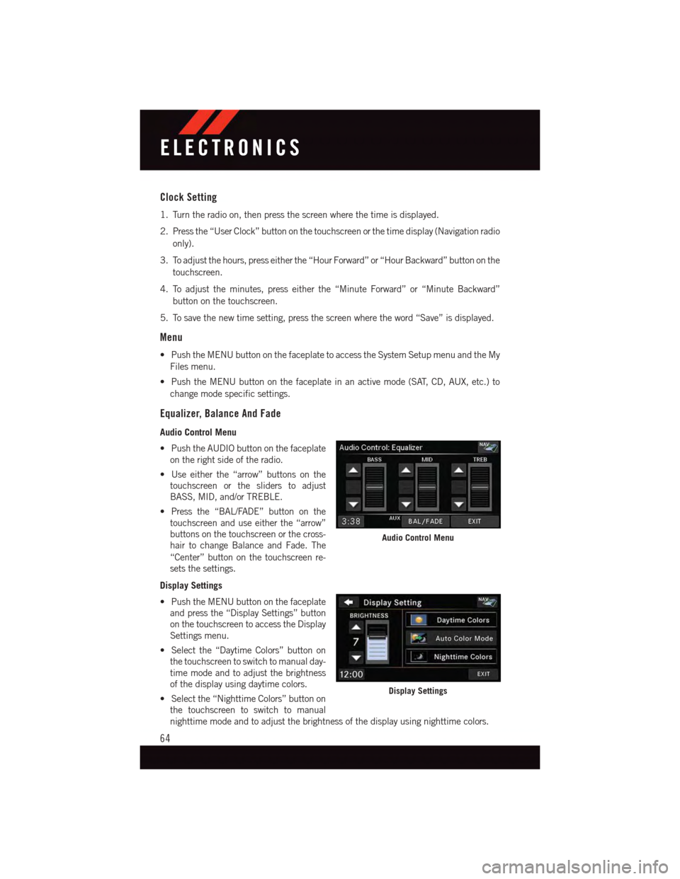
Equalizer, Balance And Fade
Audio Control Menu
•PushtheAUDIObuttononthefaceplate
on the right side of the radio.
•Useeitherthe“arrow”buttonsonthe
touchscreen or the sliders to adjust
BASS, MID, and/or TREBLE.
•Pressthe“BAL/FADE”buttononthe
touchscreen and use either the “arrow”
buttons on the touchscreen or the cross-
hair to change Balance and Fade. The
“Center” button on the touchscreen re-
sets the settings.
Display Settings
•PushtheMENUbuttononthefaceplate
and press the “Display Settings” button
on the touchscreen to access the Display
Settings menu.
•Selectthe“DaytimeColors”buttonon
the touchscreen to switch to manual day-
time mode and to adjust the brightness
of the display using daytime colors.
•Selectthe“NighttimeColors”buttonon
the touchscreen to switch to manual
nighttime mode and to adjust the brightness of the display using nighttime colors.
Audio Control Menu
Display Settings
ELECTRONICS
64
Page 121 of 164

3. Turn the compact spare tire so that the valve stem is down, and place the tire into the
spare tire/cover assembly. Slide the wheel spacer through the center of the wheel and
spare tire/cover assembly, so that the two retainer tabs snap out and engage the spare
tire cover on the opposite side.
4. Using the winch T-handle, rotate the drive nut to the right until the compact spare
tire/cover assembly is drawn into place against the underside of the vehicle.
5. Continue to rotate the nut to the right until you hear the winch mechanism click three
times. It cannot be overtightened. Check under the vehicle to ensure the compact
spare tire/cover assembly is positioned correctly against the underside of the vehicle.
Road Tire Installation
Vehicles Equipped With Wheel Covers
1. Mount the road tire on the axle.
2. To ease the installation process for steel wheels with wheel covers, install two lug nuts
on the mounting studs which are on each side of the valve stem. Install the lug nuts
with the cone shaped end of the nut toward the wheel. Lightly tighten the lug nuts.
3. Align the valve notch in the wheel cover
with the valve stem on the wheel. Install
the cover by hand, snapping the cover
over the two lug nuts. Do not use a
hammer or excessive force to install the
cover.
4. Install the remaining lug nuts with the
cone shaped end of the nut toward the
wheel. Lightly tighten the lug nuts.
5. Lower the vehicle to the ground by turn-
ing the jack handle counterclockwise.
6. Finish tightening the lug nuts. Push
down on the wrench while at the end of
the handle for increased leverage.
Ti g h t e n t h e l u g n u t s i n a s t a r p a t t e r n
until each nut has been tightened twice.
The correct tightness of each lug nut is
100 ft/lbs (135 N·m). If in doubt about
the correct tightness, have them checked with a torque wrench by your authorized
dealer or service station.
7. After 25 miles (40 km) check the lug nut torque with a torque wrench to ensure that
all lug nuts are properly seated against the wheel.
Wheel Cover Installation
1—ValveStem2—ValveNotch3—WheelLugNut4—WheelCover5—MountingStud
WHAT TO DO IN EMERGENCIES
119
Page 122 of 164

Vehicles Without Wheel Covers
1. Mount the road tire on the axle.
2. Install the remaining lug nuts with the cone shaped end of the nut toward the wheel.
Lightly tighten the lug nuts.
3. Lower the vehicle to the ground by turning the jack handle counterclockwise.
4. Finish tightening the lug nuts. Push down on the wrench while at the end of the handle
for increased leverage. Tighten the lug nuts in a star pattern until each nut has been
tightened twice. The correct tightness of each lug nut is 100 ft/lbs (135 N·m). If in
doubt about the correct tightness, have them checked with a torque wrench by your
authorized dealer or service station.
5. After 25 miles (40 km) check the lug nut torque with a torque wrench to ensure that
all lug nuts are properly seated against the wheel.
CAUTION!
•ThewinchmechanismisdesignedforusewiththewinchT-handleonly.Useofair
wrench or other power tools is not recommended and can damage the winch.
•Donotattempttoraisethevehiclebyjackingonlocationsotherthanthose
indicated in the Jacking Instructions for this vehicle.
•Besuretomountthesparetirewiththevalvestemfacingoutward.Thevehicle
could be damaged if the spare tire is mounted incorrectly.
•Thecompactsparetire/coverassemblymustbeusedwhenthecompactsparetire
is stored. Failure to use this cover could drastically reduce the life of the compact
spare tire.
•Thewinchmechanismisdesignedspecificallytostowacompactsparetireonly.Do
not attempt to use the winch to stow the full size flat tire, or any other full-size tire.
Vehicle damage may result.
WHAT TO DO IN EMERGENCIES
120
Page 141 of 164

Cavity Cartridge Fuse Mini-FuseDescription
J19 60 Amp Yellow –Radiator Fan
J20 30 Amp Pink –Front Wiper LO/HI
J21 20 Amp Blue –Front/Rear Washer
J22 25 Amp Clear –Sunroof Module
M1–15AmpBlueRear Center Brake Lamp/BrakeSwitch
M2–20AmpYellow FrontFogLamps
M3–20AmpYellowFront/Rear Axle Locker, VacuumPump Motor
M4–10AmpRedTr a i l e r To w
M5–25AmpClearInverter
M6–20AmpYellowPower Outlet #1 (ACC), Rain Sen-sor, Cigar Lighter (InstrumentPanel or with Console Rear)
M7–20AmpYellowPower Outlet #2 (BATT/ACC SE-LECT) – Center Seat or with Con-sole Rear
M8–20AmpYellowFrontHeatedSeat–IfEquipped
M9–20AmpYellowRearHeatedSeat–IfEquipped
M10–15AmpBlue
Ignition Off Draw — Video Sys-tem, Satellite Radio, DVD, Hands-Free Module, Universal GarageDoor Opener, Vanity Lamp,Streaming Video Module – IfEquipped
M11–10AmpRedClimateControlSystem
M12–30AmpGreenAmplifier/Radio
M13–20AmpYellowInstrument Cluster, SIREN, ClockModule, Multi-Function ControlSwitch – If Equipped
M14–20AmpYellowTrailerTow–IfEquipped
M15–20AmpYellow
Rear View Mirror, Instrument Clus-ter, Multi-Function Control Switch,Ti r e P r e s s u r e M o n i t o r, G l o w P l u gModule – If Equipped
M16–10AmpRedAirbag Module/Occupant Classifi-cation Module
M17–15AmpBlueLeft Tail/License/Park Lamp, Run-ning Lamps
M18–15AmpBlueRightTail/Park/RunLamp
M19–25AmpClearPowertrain
M20–15AmpBlueInstrument Cluster Interior Light,Switch Bank, Steering ColumnModule, Switch Steering Wheel
MAINTAINING YOUR VEHICLE
139