2015 DODGE GRAND CARAVAN ad blue
[x] Cancel search: ad bluePage 3 of 164

INTRODUCTION/WELCOME
WELCOME FROM CHRYSLERGROUP LLC..................3
CONTROLS AT A GLANCE
DRIVER COCKPIT...............6INSTRUMENT CLUSTER...........8
GETTING STARTED
KEY FOB . . . . . . . . . . . . . . . . . . . 10REMOTE START . . . . . . . . . . . . . . . 11KEYLESS ENTER-N-GO™.........12VEHICLE SECURITY ALARM........16SEAT BELT SYSTEMS............17SUPPLEMENTAL RESTRAINT SYSTEM(SRS) — AIR BAGS.............18CHILD RESTRAINTS............21HEAD RESTRAINTS.............26FRONT SEATS................28REAR SEATS.................31HEATED SEATS . . . . . . . . . . . . . . . 36HEATED STEERING WHEEL........37TILT/TELESCOPING STEERINGCOLUMN...................38
OPERATING YOUR VEHICLE
ENGINE BREAK-INRECOMMENDATIONS............39TURN SIGNAL/WIPER/WASHER/HIGHBEAM LEVER.................40HEADLIGHT SWITCH AND HALO LIGHTSWITCH....................42ELECTRONIC SPEED CONTROL......43ELECTRONIC RANGE SELECTION (ERS) . . 45FUEL ECONOMY (ECON) MODE......46MANUAL CLIMATE CONTROLS.......47THREE ZONE MANUAL CLIMATECONTROLS..................48THREE ZONE AUTOMATIC TEMPERATURECONTROLS (ATC)...............50PA R K S E N S E®REAR PARK ASSIST....52PA R K V I E W®REAR BACK-UP CAMERA . . 52BLIND SPOT MONITORING WITH REARCROSS PATH.................52POWER SLIDING SIDE DOORS.......53POWER LIFTGATE..............53POWER SUNROOF..............54WIND BUFFETING..............55
ELECTRONICS
YOUR VEHICLE'S SOUND SYSTEM....56Uconnect®130 . . . . . . . . . . . . . . . . 58Uconnect®130 WITH SiriusXM SATELLITERADIO.....................60Uconnect®430/430N............63
SiriusXM SATELLITE RADIO/TRAVELLINK......................73STEERING WHEEL AUDIO CONTROLS . . 77iPod®/USB/MP3 CONTROL.........77Uconnect®PHONE..............78Uconnect®VOICE COMMAND........81Bluetooth®STREAMING AUDIO......84VIDEO ENTERTAINMENT SYSTEM(VES™)....................84ELECTRONIC VEHICLE INFORMATIONCENTER (EVIC)................86PROGRAMMABLE FEATURES.......87UNIVERSAL GARAGE DOOR OPENER(HomeLink®).................89POWER INVERTER.............91POWER OUTLETS..............92
UTILITY
IN-FLOOR STORAGE — STOW'N GO®...94ROOF LUGGAGE RACK...........94TRAILER TOWING WEIGHTS (MAXIMUMTRAILER WEIGHT RATINGS)........95RECREATIONAL TOWING (BEHINDMOTORHOME, ETC.)............96
WHAT TO DO IN EMERGENCIES
ROADSIDE ASSISTANCE..........97INSTRUMENT CLUSTER WARNINGLIGHTS....................97INSTRUMENT CLUSTER INDICATORLIGHTS...................101IF YOUR ENGINE OVERHEATS......103TIRE SERVICE KIT.............103JACKING AND TIRE CHANGING.....110JUMP-STARTING..............122SHIFT LEVER OVERRIDE.........124TOWING A DISABLED VEHICLE.....124FREEING A STUCK VEHICLE.......125EVENT DATA RECORDER (EDR).....126
MAINTAINING YOUR VEHICLE
OPENING THE HOOD...........127ENGINE COMPARTMENT.........128FLUID CAPACITIES............130FLUIDS, LUBRICANTS AND GENUINEPA RT S . . . . . . . . . . . . . . . . . . . . 1 3 0MAINTENANCE PROCEDURES......132MAINTENANCE SCHEDULE.......132MAINTENANCE RECORD.........136FUSES....................137TIRE PRESSURES.............141SPARE TIRES — IF EQUIPPED.....142ADDING FUEL................144WHEEL AND WHEEL TRIM CARE....145REPLACEMENT BULBS..........146
TABLE OF CONTENTS
Page 81 of 164
NOTE:
The Uconnect®Phone requires a mobile phone equipped with the Bluetooth®Hands-
Free Profile, Version 1.0 or higher. For Uconnect®Customer Support: U.S. residents - visit
UconnectPhone.com or call 1–877–855–8400. Canadian residents - visit
UconnectPhone.com or call, 1-800-465–2001 (English) or 1-800-387-9983 (French).
This site will provide specific instructions based on the type of mobile phone being paired.
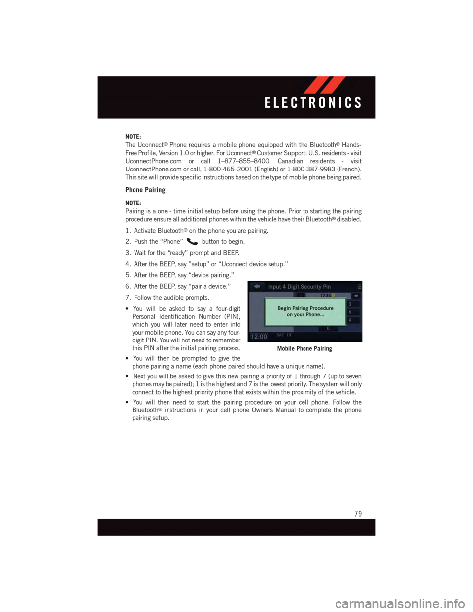
Phone Pairing
NOTE:
Pairing is a one - time initial setup before using the phone. Prior to starting the pairing
procedure ensure all additional phones within the vehicle have their Bluetooth®disabled.
1. Activate Bluetooth®on the phone you are pairing.
2. Push the “Phone”button to begin.
3. Wait for the “ready” prompt and BEEP.
4. After the BEEP, say ”setup” or “Uconnect device setup.”
5. After the BEEP, say “device pairing.”
6. After the BEEP, say “pair a device.”
7. Follow the audible prompts.
•Youwillbeaskedtosayafour-digit
Personal Identification Number (PIN),
which you will later need to enter into
your mobile phone. You can say any four-
digit PIN. You will not need to remember
this PIN after the initial pairing process.
•Youwillthenbepromptedtogivethe
phone pairing a name (each phone paired should have a unique name).
•Nextyouwillbeaskedtogivethisnewpairingapriorityof1through7(uptoseven
phones may be paired); 1 is the highest and 7 is the lowest priority. The system will only
connect to the highest priority phone that exists within the proximity of the vehicle.
•Youwillthenneedtostartthepairingprocedureonyourcellphone.Followthe
Bluetooth®instructions in your cell phone Owner's Manual to complete the phone
pairing setup.
Mobile Phone Pairing
ELECTRONICS
79
Page 82 of 164
Phonebook
Phonebook Download — Automatic Phonebook Transfer From Mobile Phone
If equipped and specifically supported by your phone, Uconnect®Phone automatically
downloads names (text names) and number entries from your mobile phone’s phonebook.
Specific Bluetooth®Phones with Phone Book Access Profile may support this feature.
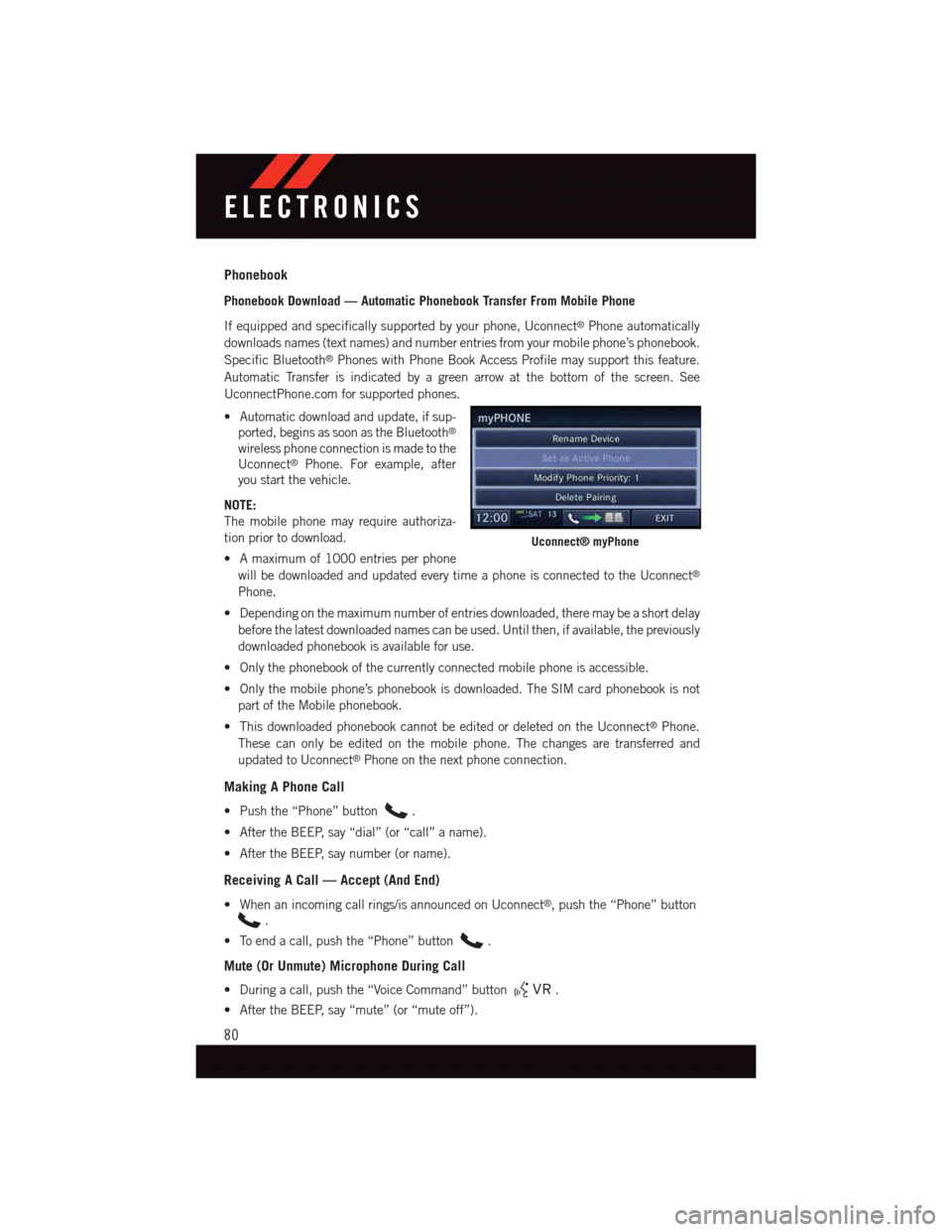
Automatic Transfer is indicated by a green arrow at the bottom of the screen. See
UconnectPhone.com for supported phones.
•Automaticdownloadandupdate,ifsup-
ported, begins as soon as the Bluetooth®
wireless phone connection is made to the
Uconnect®Phone. For example, after
you start the vehicle.
NOTE:
The mobile phone may require authoriza-
tion prior to download.
•Amaximumof1000entriesperphone
will be downloaded and updated every time a phone is connected to the Uconnect®
Phone.
•Dependingonthemaximumnumberofentriesdownloaded,theremaybeashortdelay
before the latest downloaded names can be used. Until then, if available, the previously
downloaded phonebook is available for use.
•Onlythephonebookofthecurrentlyconnectedmobilephoneisaccessible.
•Onlythemobilephone’sphonebookisdownloaded.TheSIMcardphonebookisnot
part of the Mobile phonebook.
•ThisdownloadedphonebookcannotbeeditedordeletedontheUconnect®Phone.
These can only be edited on the mobile phone. The changes are transferred and
updated to Uconnect®Phone on the next phone connection.
Making A Phone Call
•Pushthe“Phone”button.
•AftertheBEEP,say“dial”(or“call”aname).
•AftertheBEEP,saynumber(orname).
Receiving A Call — Accept (And End)
•Whenanincomingcallrings/isannouncedonUconnect®,pushthe“Phone”button
.
•Toendacall,pushthe“Phone”button.
Mute (Or Unmute) Microphone During Call
•Duringacall,pushthe“VoiceCommand”button.
•AftertheBEEP,say“mute”(or“muteoff”).
Uconnect® myPhone
ELECTRONICS
80
Page 84 of 164
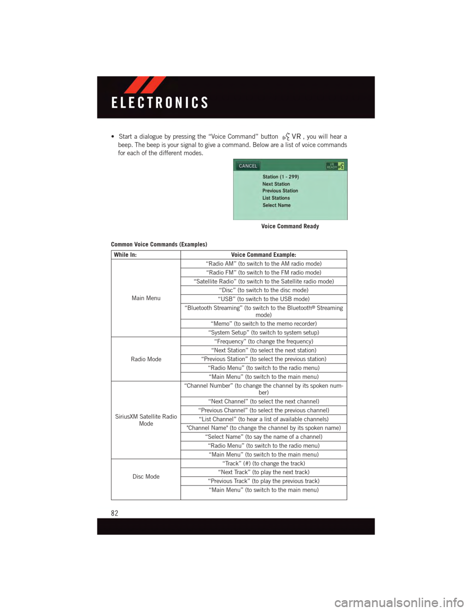
•Startadialoguebypressingthe“VoiceCommand”button,youwillheara
beep. The beep is your signal to give a command. Below are a list of voice commands
for each of the different modes.
Common Voice Commands (Examples)
While In:Voice Command Example:
Main Menu
“Radio AM” (to switch to the AM radio mode)
“Radio FM” (to switch to the FM radio mode)
“Satellite Radio” (to switch to the Satellite radio mode)
“Disc” (to switch to the disc mode)
“USB” (to switch to the USB mode)
“Bluetooth Streaming” (to switch to the Bluetooth®Streamingmode)
“Memo” (to switch to the memo recorder)
“System Setup” (to switch to system setup)
Radio Mode
“Frequency” (to change the frequency)
“Next Station” (to select the next station)
“Previous Station” (to select the previous station)
“Radio Menu” (to switch to the radio menu)
“Main Menu” (to switch to the main menu)
SiriusXM Satellite RadioMode
“Channel Number” (to change the channel by its spoken num-ber)
“Next Channel” (to select the next channel)
“Previous Channel” (to select the previous channel)
“List Channel” (to hear a list of available channels)
"Channel Name" (to change the channel by its spoken name)
“Select Name” (to say the name of a channel)
“Radio Menu” (to switch to the radio menu)
“Main Menu” (to switch to the main menu)
Disc Mode
“Track” (#) (to change the track)
“Next Track” (to play the next track)
“Previous Track” (to play the previous track)
“Main Menu” (to switch to the main menu)
Voice Command Ready
ELECTRONICS
82
Page 85 of 164
While In:Voice Command Example:
Memo Mode
To s w i t c h t o t h e v o i c e r e c o r d e r m o d e , s a y “ M e m o . ” T h e f o l l o w -ing are common voice commands for this mode: “New Memo”(to record a new memo) — During the recording, you may pressthe Voice Command buttonto stop recording. You pro-ceed by saying one of the following commands:
—“Save”(tosavethememo)
—“Continue”(tocontinuerecording)
—“Delete”(todeletetherecording)
—“PlayMemos”(toplaypreviouslyrecordedmemos)—Dur-ing the playback you may press the Voice Command buttonto stop playing memos. You proceed by saying one ofthe following commands:
—“Repeat”(torepeatamemo)
—“Next”(toplaythenextmemo)
—“Previous”(toplaythepreviousmemo)
—“Delete”(todeleteamemo)
—“DeleteAll”(todeleteallmemos)
Voice Text Reply
If equipped with Uconnect®Voice Command, your Uconnect®430N/730N radio may be
able to play incoming Short Message Service (SMS) messages (text messages) through
the vehicle's sound system. It also allows you to respond by selecting from various
predefined phrases.
NOTE:
Not all phones are compatible with this feature. Refer to the phone compatibility list at
UconnectPhone.com. Connected mobile phones must be bluetooth-compatible and
paired with your radio.
•Pushthe“VoiceCommand”buttonand after the BEEP, say “SMS” to get
started.
NOTE:
To a c c e s s t h e t u t o r i a l , p u s h t h e “ V o i c e C o m m a n d ” b u t t o n.AftertheBEEP,say
“tutorial.” Push any button on the faceplate or press any button on the touchscreen to
cancel the tutorial.
WARNING!
Any voice commanded system should be used only in safe driving conditions following
applicable laws regarding phone use. Your attention should be focused on safely
operating the vehicle. Failure to do so may result in a collision causing you and others
to be severely injured or killed.
ELECTRONICS
83
Page 86 of 164
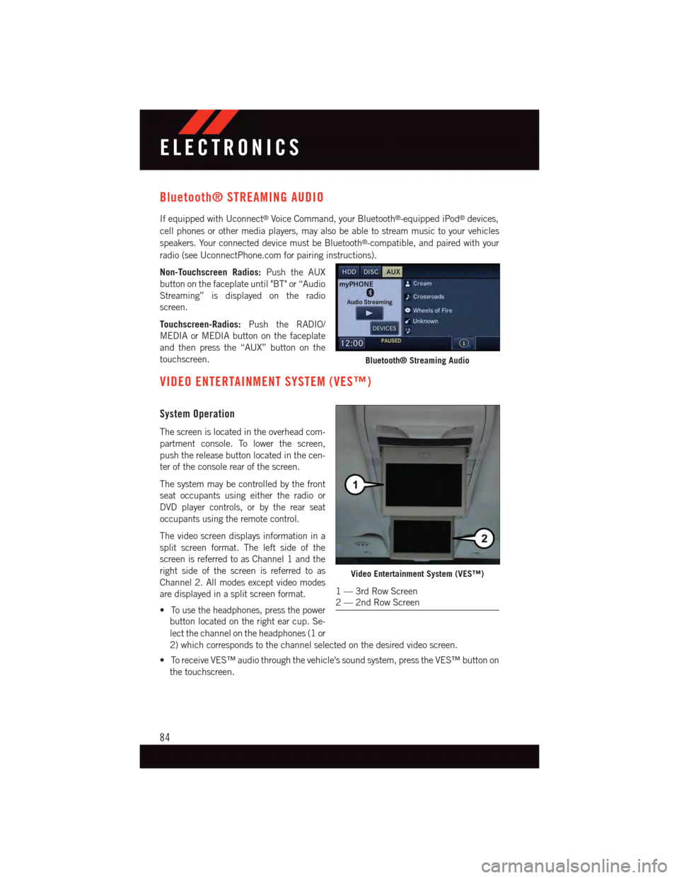
Bluetooth® STREAMING AUDIO
If equipped with Uconnect®Voice Command, your Bluetooth®-equipped iPod®devices,
cell phones or other media players, may also be able to stream music to your vehicles
speakers. Your connected device must be Bluetooth®-compatible, and paired with your
radio (see UconnectPhone.com for pairing instructions).
Non-Touchscreen Radios:Push the AUX
button on the faceplate until "BT" or “Audio
Streaming” is displayed on the radio
screen.
Touchscreen-Radios:Push the RADIO/
MEDIA or MEDIA button on the faceplate
and then press the “AUX” button on the
touchscreen.
VIDEO ENTERTAINMENT SYSTEM (VES™)
System Operation
The screen is located in the overhead com-
partment console. To lower the screen,
push the release button located in the cen-
ter of the console rear of the screen.
The system may be controlled by the front
seat occupants using either the radio or
DVD player controls, or by the rear seat
occupants using the remote control.
The video screen displays information in a
split screen format. The left side of the
screen is referred to as Channel 1 and the
right side of the screen is referred to as
Channel 2. All modes except video modes
are displayed in a split screen format.
•Tousetheheadphones,pressthepower
button located on the right ear cup. Se-
lect the channel on the headphones (1 or
2) which corresponds to the channel selected on the desired video screen.
•ToreceiveVES™audiothroughthevehicle'ssoundsystem,presstheVES™buttonon
the touchscreen.
Bluetooth® Streaming Audio
Video Entertainment System (VES™)
1—3rdRowScreen2—2ndRowScreen
ELECTRONICS
84
Page 140 of 164
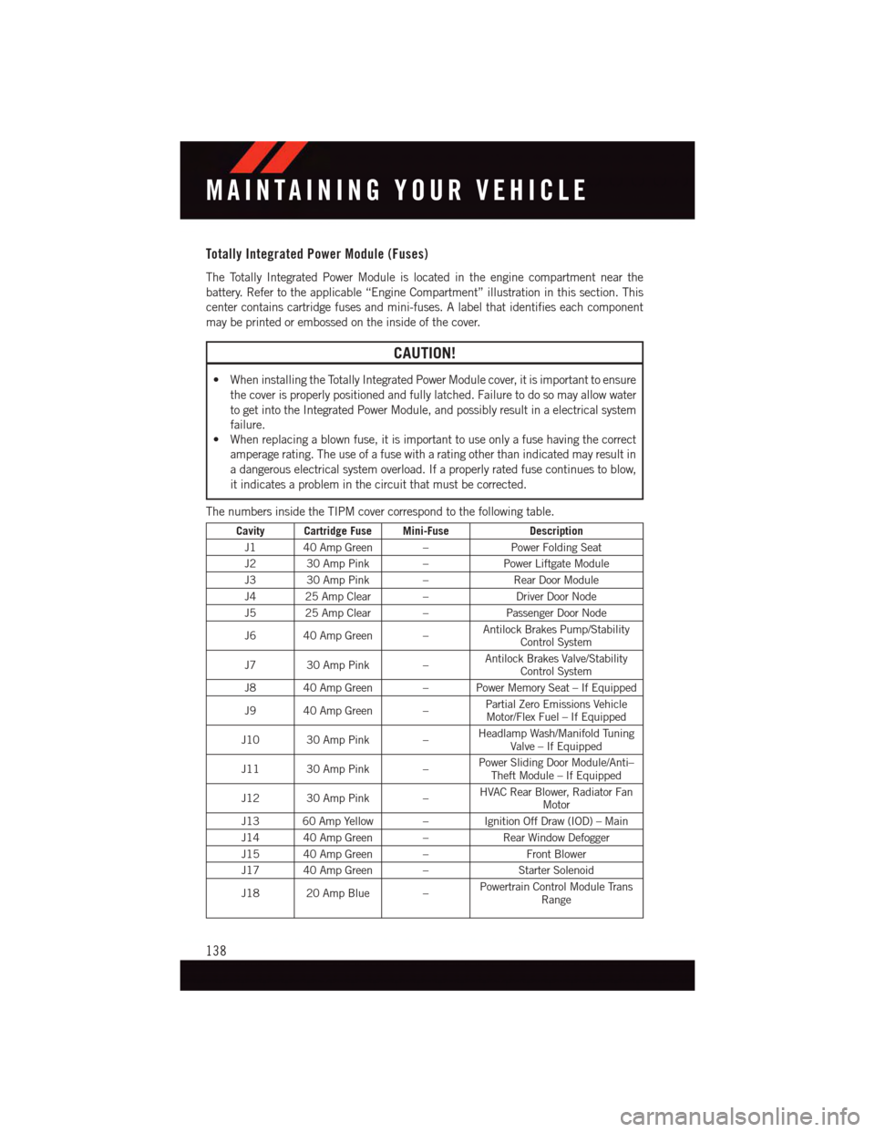
Totally Integrated Power Module (Fuses)
The Totally Integrated Power Module is located in the engine compartment near the
battery. Refer to the applicable “Engine Compartment” illustration in this section. This
center contains cartridge fuses and mini-fuses. A label that identifies each component
may be printed or embossed on the inside of the cover.
CAUTION!
•WheninstallingtheTotallyIntegratedPowerModulecover,itisimportanttoensure
the cover is properly positioned and fully latched. Failure to do so may allow water
to get into the Integrated Power Module, and possibly result in a electrical system
failure.
•Whenreplacingablownfuse,itisimportanttouseonlyafusehavingthecorrect
amperage rating. The use of a fuse with a rating other than indicated may result in
adangerouselectricalsystemoverload.Ifaproperlyratedfusecontinuestoblow,
it indicates a problem in the circuit that must be corrected.
The numbers inside the TIPM cover correspond to the following table.
Cavity Cartridge Fuse Mini-FuseDescription
J1 40 Amp Green –Power Folding Seat
J2 30 Amp Pink –Power Liftgate Module
J3 30 Amp Pink –Rear Door Module
J4 25 Amp Clear –Driver Door Node
J5 25 Amp Clear –Passenger Door Node
J6 40 Amp Green –Antilock Brakes Pump/StabilityControl System
J7 30 Amp Pink –Antilock Brakes Valve/StabilityControl System
J8 40 Amp Green – Power Memory Seat – If Equipped
J9 40 Amp Green –Partial Zero Emissions VehicleMotor/Flex Fuel – If Equipped
J10 30 Amp Pink –Headlamp Wash/Manifold TuningValve – If Equipped
J11 30 Amp Pink –Power Sliding Door Module/Anti–Theft Module – If Equipped
J12 30 Amp Pink –HVAC Rear Blower, Radiator FanMotor
J13 60 Amp Yellow – Ignition Off Draw (IOD) – Main
J14 40 Amp Green –Rear Window Defogger
J15 40 Amp Green –Front Blower
J17 40 Amp Green –Starter Solenoid
J18 20 Amp Blue –Powertrain Control Module TransRange
MAINTAINING YOUR VEHICLE
138
Page 141 of 164

Cavity Cartridge Fuse Mini-FuseDescription
J19 60 Amp Yellow –Radiator Fan
J20 30 Amp Pink –Front Wiper LO/HI
J21 20 Amp Blue –Front/Rear Washer
J22 25 Amp Clear –Sunroof Module
M1–15AmpBlueRear Center Brake Lamp/BrakeSwitch
M2–20AmpYellow FrontFogLamps
M3–20AmpYellowFront/Rear Axle Locker, VacuumPump Motor
M4–10AmpRedTr a i l e r To w
M5–25AmpClearInverter
M6–20AmpYellowPower Outlet #1 (ACC), Rain Sen-sor, Cigar Lighter (InstrumentPanel or with Console Rear)
M7–20AmpYellowPower Outlet #2 (BATT/ACC SE-LECT) – Center Seat or with Con-sole Rear
M8–20AmpYellowFrontHeatedSeat–IfEquipped
M9–20AmpYellowRearHeatedSeat–IfEquipped
M10–15AmpBlue
Ignition Off Draw — Video Sys-tem, Satellite Radio, DVD, Hands-Free Module, Universal GarageDoor Opener, Vanity Lamp,Streaming Video Module – IfEquipped
M11–10AmpRedClimateControlSystem
M12–30AmpGreenAmplifier/Radio
M13–20AmpYellowInstrument Cluster, SIREN, ClockModule, Multi-Function ControlSwitch – If Equipped
M14–20AmpYellowTrailerTow–IfEquipped
M15–20AmpYellow
Rear View Mirror, Instrument Clus-ter, Multi-Function Control Switch,Ti r e P r e s s u r e M o n i t o r, G l o w P l u gModule – If Equipped
M16–10AmpRedAirbag Module/Occupant Classifi-cation Module
M17–15AmpBlueLeft Tail/License/Park Lamp, Run-ning Lamps
M18–15AmpBlueRightTail/Park/RunLamp
M19–25AmpClearPowertrain
M20–15AmpBlueInstrument Cluster Interior Light,Switch Bank, Steering ColumnModule, Switch Steering Wheel
MAINTAINING YOUR VEHICLE
139