2015 DODGE DURANGO change time
[x] Cancel search: change timePage 26 of 689

Headlight Illumination On Approach
This feature activates the headlights for up to 90 seconds
when the doors are unlocked with the RKE transmitter.
The time for this feature is programmable on vehicles
equipped through Uconnect®. To change the current
setting, refer to “Uconnect® Settings” in “Understanding
Your Instrument Panel” for further information.
To Lock The Doors And Liftgate
Push and release the LOCK button on the RKE transmit-
ter to lock all doors and liftgate. The turn signal lights
will flash, and the horn will chirp to acknowledge the
signal.
If the vehicle is equipped with Passive Entry, refer to
“Keyless Enter-N-Go™” in “Things To Know Before
Starting Your Vehicle” for further information.
Sound Horn With Lock
This feature will cause the horn to chirp when the doors
are locked with the RKE transmitter. This feature can be
turned on or turned off. To change the current setting,
refer to “Uconnect® Settings” in “Understanding Your
Instrument Panel” for further information.
Using The Panic Alarm
To turn the Panic Alarm feature on or off, push and hold
the PANIC button on the RKE transmitter for at least one
second and release. When the Panic Alarm is activated,
the turn signals will flash, the horn will pulse on and off,
and the interior lights will turn on.
The Panic Alarm will stay on for three minutes unless
you turn it off by either pushing the PANIC button a
second time or drive the vehicle at a speed of 15 MPH
(24 km/h) or greater.
24 THINGS TO KNOW BEFORE STARTING YOUR VEHICLE
Page 112 of 689

Whenever a change is noticed in the sound of the exhaust
system, when exhaust fumes can be detected inside the
vehicle, or when the underside or rear of the vehicle is
damaged, have a competent mechanic inspect the com-
plete exhaust system and adjacent body areas for broken,
damaged, deteriorated, or mispositioned parts. Open
seams or loose connections could permit exhaust fumes
to seep into the passenger compartment. In addition,
inspect the exhaust system each time the vehicle is raised
for lubrication or oil change. Replace as required.
Safety Checks You Should Make Inside The
Vehicle
Seat Belts
Inspect the seat belt system periodically, checking for
cuts, frays, and loose parts. Damaged parts must be
replaced immediately. Do not disassemble or modify the
system.
Front seat belt assemblies must be replaced after a
collision. Rear seat belt assemblies must be replaced after
a collision if they have been damaged (i.e., bent retractor,
torn webbing, etc.). If there is any question regarding seat
belt or retractor condition, replace the seat belt.
Air Bag Warning Light
The light should come on and remain on for
four to eight seconds as a bulb check when the
ignition switch is first turned ON. If the light is
not lit during starting, see your authorized
dealer. If the light stays on, flickers, or comes on while
driving, have the system checked by an authorized
dealer.
Defroster
Check operation by selecting the defrost mode and place
the blower control on high speed. You should be able to
11 0 T H I N G S TO K N O W B E F O R E S TA R T I N G Y O U R V E H I C L E
Page 134 of 689

The BSM detection zone covers approximately one lane
on both sides of the vehicle (12 ft or 3.8 m). The zone
length starts at the outside rear view mirror and extends
approximately 10 ft (3 m) beyond the rear bumper of the
vehicle. The BSM system monitors the detection zones on
both sides of the vehicle when the vehicle speed has
reached approximately 6 mph (10 km/h) or higher and
will alert the driver of vehicles in these areas.
NOTE:
•The BSM system does NOT alert the driver about
rapidly approaching vehicles that are outside the de-
tection zones.
•The BSM system detection zone DOES NOT change if
your vehicle is towing a trailer. Therefore, visually
verify the adjacent lane is clear for both your vehicle
and trailer before making a lane change. If the trailer or
other object (i.e., bicycle, sports equipment) extends
beyond the side of your vehicle, this may result in the
BSM warning light remaining illuminated or the alert
chime remaining on the entire time the vehicle is in a
forward gear. Refer to “Uconnect® Settings” in “Un-
derstanding Your Instrument Panel” for more informa-
tion.
The area on the rear fascia where the radar sensors are
located must remain free of snow, ice, and dirt/road
contamination so that the BSM system can function
properly. Do not block the area of the rear fascia where
the radar sensors are located with foreign objects (bum-
per stickers, bicycle racks, etc.).
132 UNDERSTANDING THE FEATURES OF YOUR VEHICLE
Page 142 of 689

Blind Spot Alert Off
When the BSM system is turned off there will be no
visual or audible alerts from either the BSM or RCP
systems.
NOTE:The BSM system will store the current operating
mode when the vehicle is shut off. Each time the vehicle
is started the previously stored mode will be recalled and
used.
General Information
This vehicle has systems that operate on radio frequency
that comply with Part 15 of the Federal Communications
Commission (FCC) rules and with Industry Canada
Standards RSS- GEN/210/220/310.
Operation is subject to the following two conditions:
1. The device may not cause harmful interference.
2. The device must accept any interference received,
including interference that may cause undesired op-
eration of the device.
Changes or modifications to any of these systems by
other than an authorized service facility could void
authorization to use this equipment.
SEATS
Seats are part of the Occupant Restraint System of the
vehicle.
WARNING!
•It is dangerous to ride in a cargo area, inside or
outside of a vehicle. In a collision, people riding in
these areas are more likely to be seriously injured
or killed.
(Continued)
140 UNDERSTANDING THE FEATURES OF YOUR VEHICLE
Page 150 of 689

Front Heated Seats
The front heated seats control buttons are located within
the climate or controls screen of the touchscreen.
You can choose from HI, LO or OFF heat settings. The
indicator lights in each switch indicate the level of heat in
use. Two indicator lights will illuminate for HI, one for
LO and none for OFF.
•Press the heated seat buttononce to turn the HI
setting ON.
•Press the heated seat buttona second time to turn
the LO setting ON.
•Press the heated seat buttona third time to turn
the heating elements OFF.
If the HI-level setting is selected, the system will auto-
matically switch to LO-level after approximately 60 min-
utes of continuous operation. At that time, the display
will change from HI to LO, indicating the change. The
LO-level setting will turn OFF automatically after ap-
proximately 45 minutes.
NOTE:
•Once a heat setting is selected, heat will be felt within
two to five minutes.
•The engine must be running for the heated seats to
operate.
Vehicles Equipped With Remote Start
On models that are equipped with remote start, the
heated seats can be programed to come on during a
remote start.
This feature can be programmed through the Uconnect®
system. Refer to “Uconnect® Settings” in “Understand-
ing Your Instrument Panel” for further information.
148 UNDERSTANDING THE FEATURES OF YOUR VEHICLE
Page 151 of 689

Rear Heated Seats — If Equipped
On some models, the two rear outboard seats may be
equipped with heated seats. There are two heated seat
switches that allow the rear passengers to operate the
seats independently. The heated seat switches for each
heater are located on the rear of the center console.
You can choose from HI, LO or OFF heat settings. Amber
indicator lights in each switch indicate the level of heat in
use. Two indicator lights will illuminate for HI, one for
LO and none for OFF.
Press the switch once to select HI-level heating.
Press the switch a second time to select LO-
level heating. Press the switch a third time to
shut the heating elements OFF.
When the HI-level setting is selected, the heater will
provide a boosted heat level during the first four minutes
of operation. Then, the heat output will drop to the
normal HI-level. If the HI-level setting is selected, the
system will automatically switch to LO-level after ap-
proximately 60 minutes of continuous operation. At that
time, the number of illuminated LEDs changes from two
to one, indicating the change. The LO-level setting will
turn OFF automatically after approximately 45 minutes.
Rear Heated Seat Switches
3
UNDERSTANDING THE FEATURES OF YOUR VEHICLE 149
Page 183 of 689

When the Daytime Running Lights are on and a turn
signal is activated, the Daytime Running Lamp will turn
off on the side of the vehicle in which the turn signal is
flashing. The Daytime Running Lamp will turn back on
when the turn signal is turned off.
Lane Change Assist
Tap the lever up or down once, without moving beyond
the detent, and the turn signal (right or left) will flash
three times then automatically turn off.
Flash-To-Pass
You can signal another vehicle with your headlights by
partially pulling the multifunction lever toward the steer-
ing wheel. This will cause the high beam headlights to
turn on until the lever is released.
High/Low Beam Switch
Push the multifunction lever toward the instrument
panel to switch the headlights to high beam. Pulling the
multifunction back toward the steering wheel will turn
the low beams back on, or shut the high beams off.
3
UNDERSTANDING THE FEATURES OF YOUR VEHICLE 181
Page 210 of 689

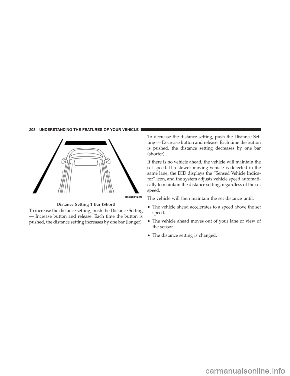
To increase the distance setting, push the Distance Setting
— Increase button and release. Each time the button is
pushed, the distance setting increases by one bar (longer).
To decrease the distance setting, push the Distance Set-
ting — Decrease button and release. Each time the button
is pushed, the distance setting decreases by one bar
(shorter).
If there is no vehicle ahead, the vehicle will maintain the
set speed. If a slower moving vehicle is detected in the
same lane, the DID displays the “Sensed Vehicle Indica-
tor” icon, and the system adjusts vehicle speed automati-
cally to maintain the distance setting, regardless of the set
speed.
The vehicle will then maintain the set distance until:
•The vehicle ahead accelerates to a speed above the set
speed.
•The vehicle ahead moves out of your lane or view of
the sensor.
•The distance setting is changed.
Distance Setting 1 Bar (Short)
208 UNDERSTANDING THE FEATURES OF YOUR VEHICLE