2015 DODGE DART ESP
[x] Cancel search: ESPPage 93 of 164

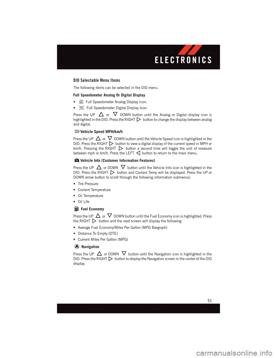
DID Selectable Menu Items
The following items can be selected in the DID menu.
Full Speedometer Analog Or Digital Display
•Full Speedometer Analog Display Icon.
•Full Speedometer Digital Display Icon.
Press the UPorDOWN button until the Analog or Digital display icon is
highlighted in the DID. Press the RIGHTbutton to change the display between analog
and digital.
Vehicle Speed MPH/km/h
Press the UPorDOWN button until the Vehicle Speed icon is highlighted in the
DID. Press the RIGHTbutton to view a digital display of the current speed in MPH or
km/h. Pressing the RIGHTbutton a second time will toggle the unit of measure
between mph or km/h. Press the LEFTbutton to return to the main menu.
Vehicle Info (Customer Information Features)
Press the UPor DOWNbutton until the Vehicle Info icon is highlighted in the
DID. Press the RIGHTbutton and Coolant Temp will be displayed. Press the UP or
DOWN arrow button to scroll through the following information submenus:
•TirePressure
•CoolantTemperature
•OilTemperature
•OilLife
Fuel Economy
Press the UPorDOWN button until the Fuel Economy icon is highlighted. Press
the RIGHTbutton and the next screen will display the following:
•AverageFuelEconomy/MilesPerGallon(MPGBargraph)
•DistanceToEmpty(DTE)
•CurrentMilesPerGallon(MPG)
Navigation
Press the UPor DOWNbutton until the Navigation icon is highlighted in the
DID. Press the RIGHTbutton to display the Navigation screen in the center of the DID
display.
ELECTRONICS
91
Page 103 of 164

NOTE:
AFTER INFLATION, THE VEHICLE MAY NEED TO BE DRIVEN FOR 20 MINUTES
BEFORE THE FLASHING LIGHT WILL TURN OFF.
Please note that the TPMS is not a substitute for proper tire maintenance, and it is the
driver’s responsibility to maintain correct tire pressure, even if under-inflation has not
reached the level to trigger illumination of the TPMS low tire pressure telltale.
Yo u r v e h i c l e h a s a l s o b e e n e q u i p p e d w i t h a T P M S m a l f u n c t i o n i n d i c a t o r t o i n d i c a t e w h e n
the system is not operating properly. The TPMS malfunction indicator is combined with
the low tire pressure telltale.
When the system detects a malfunction, the telltale will flash for approximately one
minute and then remain continuously illuminated. This sequence will continue upon
subsequent vehicle start-ups as long as the malfunction exists. When the malfunction
indicator is illuminated, the system may not be able to detect or signal low tire pressure
as intended. TPMS malfunctions may occur for a variety of reasons, including the
installation of replacement or alternate tires or wheels on the vehicle that prevent the
TPMS from functioning properly. Always check the TPMS malfunction telltale after
replacing one or more tires or wheels on your vehicle to ensure that the replacement or
alternate tires and wheels allow the TPMS to continue to function properly.
NOTE:
Ti r e p r e s s u r e s c h a n g e b y a p p r o x i m a t e l y 1 p s i ( 7 k P a ) p e r 1 2 ° F ( 7 ° C ) o f a i r t e m p e r a t u r e
change. Keep this in mind when checking tire pressure inside a garage, especially in the
Winter. Example: If garage temperature is 68°F (20°C) and the outside temperature is
32°F (0°C), then the cold tire inflation pressure should be increased by 3 psi (21 kPa),
which equals 1 psi (7 kPa) for every 12°F (7°C) for this outside temperature condition.
CAUTION!
The TPMS has been optimized for the original equipment tires and wheels. TPMS
pressures and warning have been established for the tire size equipped on your vehicle.
Undesirable system operation or sensor damage may result when using replacement
equipment that is not of the same size, type, and/or style. Aftermarket wheels can
cause sensor damage. Do not use tire sealant from a can, or balance beads if your
vehicle is equipped with a TPMS, as damage to the sensors may result.
WHAT TO DO IN EMERGENCIES
101
Page 114 of 164

Vehicles Without Wheel Covers
1. Mount the road tire on the axle.
2. Install the remaining wheel bolts with the threaded end of the wheel bolt toward the
wheel. Lightly tighten the wheel bolts.
3. Lower the vehicle to the ground by turning the jack handle counterclockwise.
4. Finish tightening the wheel bolts. Push down on the wrench while at the end of the
handle for increased leverage. Tighten the wheel bolts in a star pattern until each bolt
has been tightened twice. The correct tightness of each wheel bolt is 100 ft/lbs
(135 N·m). If in doubt about the correct tightness, have them checked with a torque
wrench by your authorized dealer or service station.
5. After 25 miles (40 km) check the wheel bolt torque with a torque wrench to ensure that
all wheel bolts are properly seated against the wheel.
CAUTION!
•Thewinchmechanismisdesignedforusewiththejack-handleonly.Useofanair
wrench or other power tools is not recommended and they can damage the winch.•Donotattempttoraisethevehiclebyjackingonlocationsotherthanthose
indicated in the Jacking Instructions for this vehicle.
•Besuretomountthesparetirewiththevalvestemfacingoutward.Thevehicle
could be damaged if the spare tire is mounted incorrectly.
WHAT TO DO IN EMERGENCIES
112
Page 121 of 164

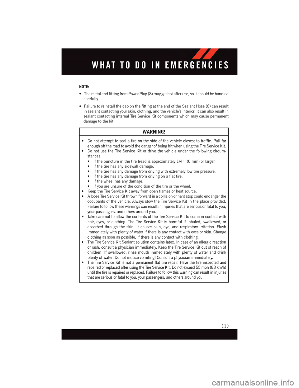
NOTE:
•ThemetalendfittingfromPowerPlug(8)maygethotafteruse,soitshouldbehandled
carefully.
•FailuretoreinstallthecaponthefittingattheendoftheSealantHose(6)canresult
in sealant contacting your skin, clothing, and the vehicle’s interior. It can also result in
sealant contacting internal Tire Service Kit components which may cause permanent
damage to the kit.
WARNING!
•Donotattempttosealatireonthesideofthevehicleclosesttotraffic.Pullfar
enough off the road to avoid the danger of being hit when using the Tire Service Kit.•DonotusetheTireServiceKitordrivethevehicleunderthefollowingcircum-
stances:
•Ifthepunctureinthetiretreadisapproximately1/4”.(6mm)orlarger.
•Ifthetirehasanysidewalldamage.
•Ifthetirehasanydamagefromdrivingwithextremelylowtirepressure.
•Ifthetirehasanydamagefromdrivingonaflattire.
•Ifthewheelhasanydamage.
•Ifyouareunsureoftheconditionofthetireorthewheel.
•KeeptheTireServiceKitawayfromopenflamesorheatsource.
•AlooseTireServiceKitthrownforwardinacollisionorhardstopcouldendangerthe
occupants of the vehicle. Always stow the Tire Service Kit in the place provided.
Failure to follow these warnings can result in injuries that are serious or fatal to you,
your passengers, and others around you.
•TakecarenottoallowthecontentsoftheTireServiceKittocomeincontactwith
hair, eyes, or clothing. The Tire Service Kit is harmful if inhaled, swallowed, or
absorbed through the skin. It causes skin, eye, and respiratory irritation. Flush
immediately with plenty of water if there is any contact with eyes or skin. Change
clothing as soon as possible, if there is any contact with clothing.
•TheTireServiceKitSealantsolutioncontainslatex.Incaseofanallergicreaction
or rash, consult a physician immediately. Keep the Tire Service Kit out of reach of
children. If swallowed, rinse mouth immediately with plenty of water and drink
plenty of water. Do not induce vomiting! Consult a physician immediately.
•The Tire Service Kit is not a permanent flat tire repair. Have the tire inspected and
repaired or replaced after using the Tire Service Kit. Do not exceed 55 mph (88 km/h)
until the tire is repaired or replaced. Failure to follow this warning can result in injuries
that are serious or fatal to you, your passengers, and others around you.
WHAT TO DO IN EMERGENCIES
119
Page 142 of 164

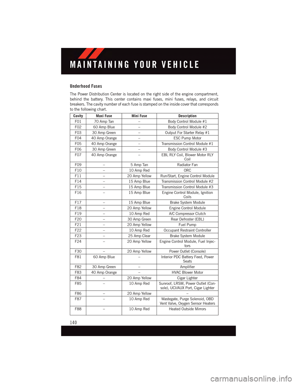
Underhood Fuses
The Power Distribution Center is located on the right side of the engine compartment,
behind the battery. This center contains maxi fuses, mini fuses, relays, and circuit
breakers. The cavity number of each fuse is stamped on the inside cover that corresponds
to the following chart.
Cavity Maxi FuseMini FuseDescription
F01 70 Amp Tan–Body Control Module #1
F02 60 Amp Blue–Body Control Module #2
F03 30 Amp Green–Output For Starter Relay #1
F04 40 Amp Orange–ESC Pump Motor
F05 40 Amp Orange–Tr a n s m i s s i o n C o n t r o l M o d u l e # 1
F06 30 Amp Green–Body Control Module #3
F07 40 Amp Orange–EBL RLY Coil, Blower Motor RLYCoil
F09–5AmpTanRadiator Fan
F10–10 Amp RedORC
F11–20 Amp Yellow Run/Start, Engine Control Module
F14–15 Amp Blue Transmission Control Module #2
F15–15 Amp Blue Transmission Control Module #3
F16–15 Amp Blue Engine Control Module, IgnitionCoils
F17–15 Amp BlueBrake System Module
F18–20 Amp Yellow Engine Control Module
F19–10 Amp RedA/C Compressor Clutch
F20–30 Amp GreenRear Defroster (EBL)
F21–20 Amp YellowFuel Pump
F22–10 Amp Red Occupant Restraint Controller
F23–25 Amp ClearBrake System Module
F24–20 Amp Yellow Engine Control Module, Fuel Injec-tors
F30–20 Amp Yellow Power Outlet (Console)
F81 60 Amp Blue–Interior PDC Battery Feed, PowerSeats
F82 30 Amp Green–Amplifier
F83 40 Amp Orange–HVAC Blower Motor
F84–20 Amp YellowCigar Lighter
F85–10 Amp Red Sunroof, LRSM, Power Outlet (Con-sole), UCI/AUX Port, Cigar Lighter
F86–20 Amp Yellow–
F87–10 Amp Red Wastegate, Purge Solenoid, OBDVent Valve, Oxygen Sensor Heaters
F88–10 Amp Red Heated Outside Mirrors
MAINTAINING YOUR VEHICLE
140
Page 146 of 164

Full Size Spare — If Equipped
The full size spare is for temporary emergency use only. This tire may look like the
originally equipped tire on the front or rear axle of your vehicle, but it is not. This spare tire
may have limited tread life. When the tread is worn to the tread wear indicators, the
temporary use full size spare tire needs to be replaced. Since it is not the same as your
original equipment tire, replace (or repair) the original equipment tire and reinstall on the
vehicle at the first opportunity.
Limited-Use Spare — If Equipped
The limited-use spare tire is for temporary emergency use only. This tire is identified by a
label located on the limited-use spare wheel. This label contains the driving limitations for
this spare. This tire may look like the original equipped tire on the front or rear axle of your
vehicle, but it is not. Installation of this limited-use spare tire affects vehicle handling.
Since it is not the same as your original equipment tire, replace (or repair) the original
equipment tire and reinstall on the vehicle at the first opportunity.
WARNING!
Limited-use spares are for emergency use only. Installation of this limited-use spare
tire affects vehicle handling. With this tire, do not drive more than the speed listed on
the limit-use spare wheel. Keep inflated to the cold tire inflation pressures listed on
your Tire and Loading Information Placard located on the driver’s side B-Pillar or the
rear edge of the driver’s side door. Replace (or repair) the original equipment tire at the
first opportunity and reinstall it on your vehicle. Failure to do so could result in loss of
vehicle control.
WHEEL AND WHEEL TRIM CARE
All wheels and wheel trim, especially aluminum and chrome plated wheels, should be
cleaned regularly with a mild soap and water to prevent corrosion.
To r e m o v e h e a v y s o i l a n d / o r e x c e s s i v e b r a k e d u s t , u s e M O PA R®Wheel Cleaner or
equivalent or select a non-abrasive, non-acidic cleaner.
CAUTION!
Do not use scouring pads, steel wool, a bristle brush, or metal polishes. Do not use oven
cleaner. These products may damage the wheel's protective finish. Avoid automatic car
washes that use acidic solutions or harsh brushes that may damage the wheel's
protective finish. Only MOPAR®Wheel Cleaner or equivalent is recommended.
MAINTAINING YOUR VEHICLE
144