2015 DODGE CHALLENGER park assist
[x] Cancel search: park assistPage 3 of 220

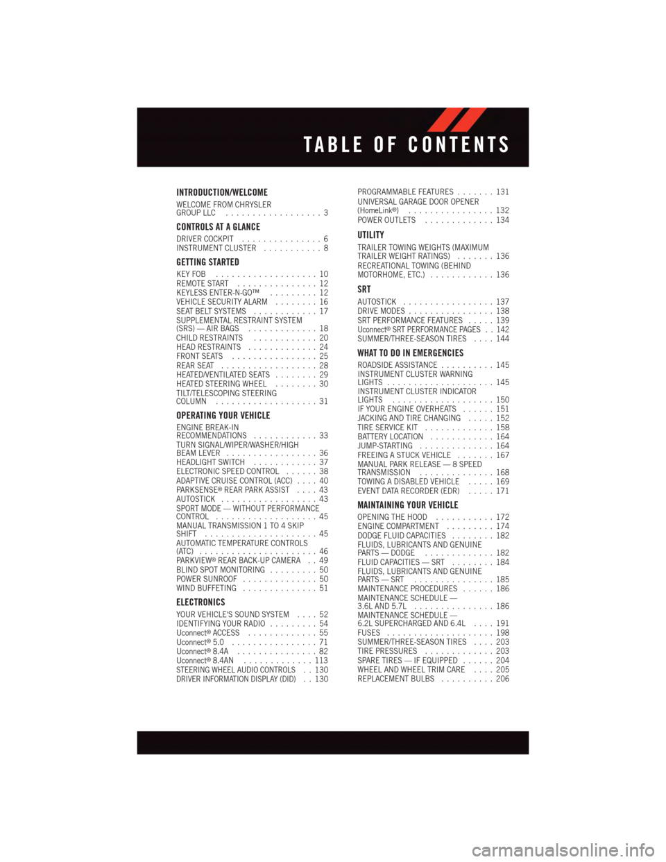
INTRODUCTION/WELCOME
WELCOME FROM CHRYSLERGROUP LLC..................3
CONTROLS AT A GLANCE
DRIVER COCKPIT...............6INSTRUMENT CLUSTER...........8
GETTING STARTED
KEY FOB . . . . . . . . . . . . . . . . . . . 10REMOTE START . . . . . . . . . . . . . . . 12KEYLESS ENTER-N-GO™.........12VEHICLE SECURITY ALARM........16SEAT BELT SYSTEMS............17SUPPLEMENTAL RESTRAINT SYSTEM(SRS) — AIR BAGS.............18CHILD RESTRAINTS............20HEAD RESTRAINTS.............24FRONT SEATS................25REAR SEAT..................28HEATED/VENTILATED SEATS........29HEATED STEERING WHEEL........30TILT/TELESCOPING STEERINGCOLUMN...................31
OPERATING YOUR VEHICLE
ENGINE BREAK-INRECOMMENDATIONS............33TURN SIGNAL/WIPER/WASHER/HIGHBEAM LEVER.................36HEADLIGHT SWITCH............37ELECTRONIC SPEED CONTROL......38ADAPTIVE CRUISE CONTROL (ACC)....40PA R K S E N S E®REAR PARK ASSIST....43AUTOSTICK..................43SPORT MODE — WITHOUT PERFORMANCECONTROL...................45MANUAL TRANSMISSION 1 TO 4 SKIPSHIFT.....................45AUTOMATIC TEMPERATURE CONTROLS(ATC) . . . . . . . . . . . . . . . . . . . . . . 46PA R K V I E W®REAR BACK-UP CAMERA . . 49BLIND SPOT MONITORING.........50POWER SUNROOF..............50WIND BUFFETING..............51
ELECTRONICS
YOUR VEHICLE'S SOUND SYSTEM....52IDENTIFYING YOUR RADIO.........54Uconnect®ACCESS.............55Uconnect®5.0 . . . . . . . . . . . . . . . . 71Uconnect®8.4A...............82Uconnect®8.4AN.............113STEERING WHEEL AUDIO CONTROLS..130DRIVER INFORMATION DISPLAY (DID)..130
PROGRAMMABLE FEATURES.......131UNIVERSAL GARAGE DOOR OPENER(HomeLink®)................132POWER OUTLETS.............134
UTILITY
TRAILER TOWING WEIGHTS (MAXIMUMTRAILER WEIGHT RATINGS).......136RECREATIONAL TOWING (BEHINDMOTORHOME, ETC.)............136
SRT
AUTOSTICK.................137DRIVE MODES................138SRT PERFORMANCE FEATURES.....139Uconnect®SRT PERFORMANCE PAGES . . 142SUMMER/THREE-SEASON TIRES....144
WHAT TO DO IN EMERGENCIES
ROADSIDE ASSISTANCE..........145INSTRUMENT CLUSTER WARNINGLIGHTS....................145INSTRUMENT CLUSTER INDICATORLIGHTS...................150IF YOUR ENGINE OVERHEATS......151JACKING AND TIRE CHANGING.....152TIRE SERVICE KIT.............158BATTERY LOCATION............164JUMP-STARTING..............164FREEING A STUCK VEHICLE.......167MANUAL PARK RELEASE — 8 SPEEDTRANSMISSION..............168TOWING A DISABLED VEHICLE.....169EVENT DATA RECORDER (EDR).....171
MAINTAINING YOUR VEHICLE
OPENING THE HOOD...........172ENGINE COMPARTMENT.........174DODGE FLUID CAPACITIES........182FLUIDS, LUBRICANTS AND GENUINEPA RT S — D O D G E.............182FLUID CAPACITIES — SRT........184FLUIDS, LUBRICANTS AND GENUINEPA RT S — S RT . . . . . . . . . . . . . . . 1 8 5MAINTENANCE PROCEDURES......186MAINTENANCE SCHEDULE —3.6L AND 5.7L...............186MAINTENANCE SCHEDULE —6.2L SUPERCHARGED AND 6.4L....191FUSES....................198SUMMER/THREE-SEASON TIRES....203TIRE PRESSURES.............203SPARE TIRES — IF EQUIPPED......204WHEEL AND WHEEL TRIM CARE....205REPLACEMENT BULBS..........206
TABLE OF CONTENTS
Page 13 of 220

Emergency Key
Should the battery in the vehicle or the Key
Fob transmitter go dead, there is an emer-
gency key located in the Key Fob that can
be used for locking and unlocking the
doors. To remove the emergency key, slide
the button at the top of the Key Fob side-
ways with your thumb and then pull the key
out with your other hand.
CAUTION!
•Ifyourvehiclebatterybecomeslowordead,yourKeyFobwillbecomelockedinthe
ignition.
•DonotattempttoremovetheKeyFobwhileinthiscondition,damagecouldoccur
to the Key Fob or ignition module. Only remove the emergency key for locking and
unlocking the doors.
•LeavetheKeyFobintheignitionandeither:
•JumpStartthevehicle.
•Chargethebattery.
•ContactyourauthorizeddealerforassistanceonhowtoremovetheKeyFob
using the manual override method.
WARNING!
•Neverleavechildrenaloneinavehicle,orwithaccesstoanunlockedvehicle.
Allowing children to be in a vehicle unattended is dangerous for a number of
reasons. A child or others could be severely injured or killed. Children should be
warned not to touch the parking brake, brake pedal, or the transmission gear
selector. Do not leave the Key Fob inside the vehicle, or in a location accessible to
children, and do not leave the ignition of a vehicle equipped with Keyless
Enter-N-Go in the ACC or ON/RUN mode. A child could start the vehicle, operate
power windows, other controls, or move the vehicle.
•Donotleavechildrenoranimalsinsideparkedvehiclesinhotweather.Interiorheat
build-up may cause them to be severely injured or killed.
•KeepKeyFobtransmittersawayfromchildren.OperationoftheRemoteStart
System, windows, door locks or other controls could cause serious injury or death.
Emergency Key
GETTING STARTED
11
Page 45 of 220

This setting provides less reaction time than the “Far” setting, which allows for a more
dynamic driving experience.
More dynamic or aggressive drivers that want to avoid frequent warnings may prefer this
setting.
Refer to the Owner's Manual on the DVD for further details.
WARNING!
Forward Collision Warning (FCW) is not intended to avoid a collision on its own, nor can
FCW detect every type of potential collision. The driver has the responsibility to avoid
acollisionbycontrollingthevehicleviabrakingandsteering.Failuretofollowthis
warning could lead to serious injury or death.
PARKSENSE® REAR PARK ASSIST
The four ParkSense®sensors, located in the rear fascia/bumper, monitor the area behind
the vehicle that is within the sensors’ field of view.
The sensors can detect obstacles from approximately 12 in (30 cm) up to 79 in (200 cm)
from the rear bumper while the vehicle is in REVERSE, a warning will display in the Driver
Information Display (DID) only when (Sound and Display is selected from the Uconnect®
System). As the vehicle moves closer to the obstacle, the (DID) will show fewer arcs and
the sound tone will change from slow, to fast, to continuous.
Refer to your Owner's Manual on the DVD for further details.
AUTOSTICK
AutoStick is a driver-interactive transmission feature providing manual shift control,
giving you more control of the vehicle. AutoStick allows you to maximize engine braking,
eliminate undesirable upshifts and downshifts, and improve overall vehicle performance.
This system can also provide you with more control during passing, city driving, cold
slippery conditions, mountain driving, trailer towing, and many other situations.
Operation
When the shift lever is in the DRIVE (D) position, the transmission will operate automatically,
shifting between the eight available gears. To activate AutoStick, move the shift lever into the
MANUAL (M) position (beside the DRIVE position). The current transmission gear will be
displayed in the instrument cluster, along with a highlighted "M" (Manual) indication. When
the shift lever is in the MANUAL (M) position, tap the shift lever forward (-) (or tap the (-) shift
paddle on the steering wheel, if equipped) to downshift the transmission to the next lower
gear, or tap the lever rearward (+) (or tap the (+) shift paddle, if equipped) to command an
upshift.
OPERATING YOUR VEHICLE
43
Page 58 of 220

3. The Uconnect®Voice Command and Uconnect®Phone buttons are located on the left
side of your steering wheel. These buttons let you use your voice to give commands,
make phone calls, send and receive text messages hands-free, enter navigation
destinations, and control your radio and media devices.
Included Trial Period For New Vehicles
Yo u r n e w v e h i c l e m a y c o m e w i t h a n i n c l u d e d t r i a l p e r i o d f o r u s e o f t h e U c o n n e c t®Access
Services starting at the date of vehicle purchase (date based on vehicle sales notification
from your dealer).To activate the trial, you must first register with Uconnect® Access.
After the trial period, if you wish to continue your Uconnect®Access Services you can
choose to purchase a subscription.
Features And Packages
•Afterthetrialperiod,youcansubscribetocontinueyourservicebyvisitingthe
Uconnect®Store located within the Mopar Owner Connect website
moparownerconnect.com. If you need assistance, U.S. residents can call Uconnect®
Care at 1-855-792-4241.
•Forthelatestinformationonpackagesandpricinginformation:U.S.residentsvisit
DriveUconnect.com.
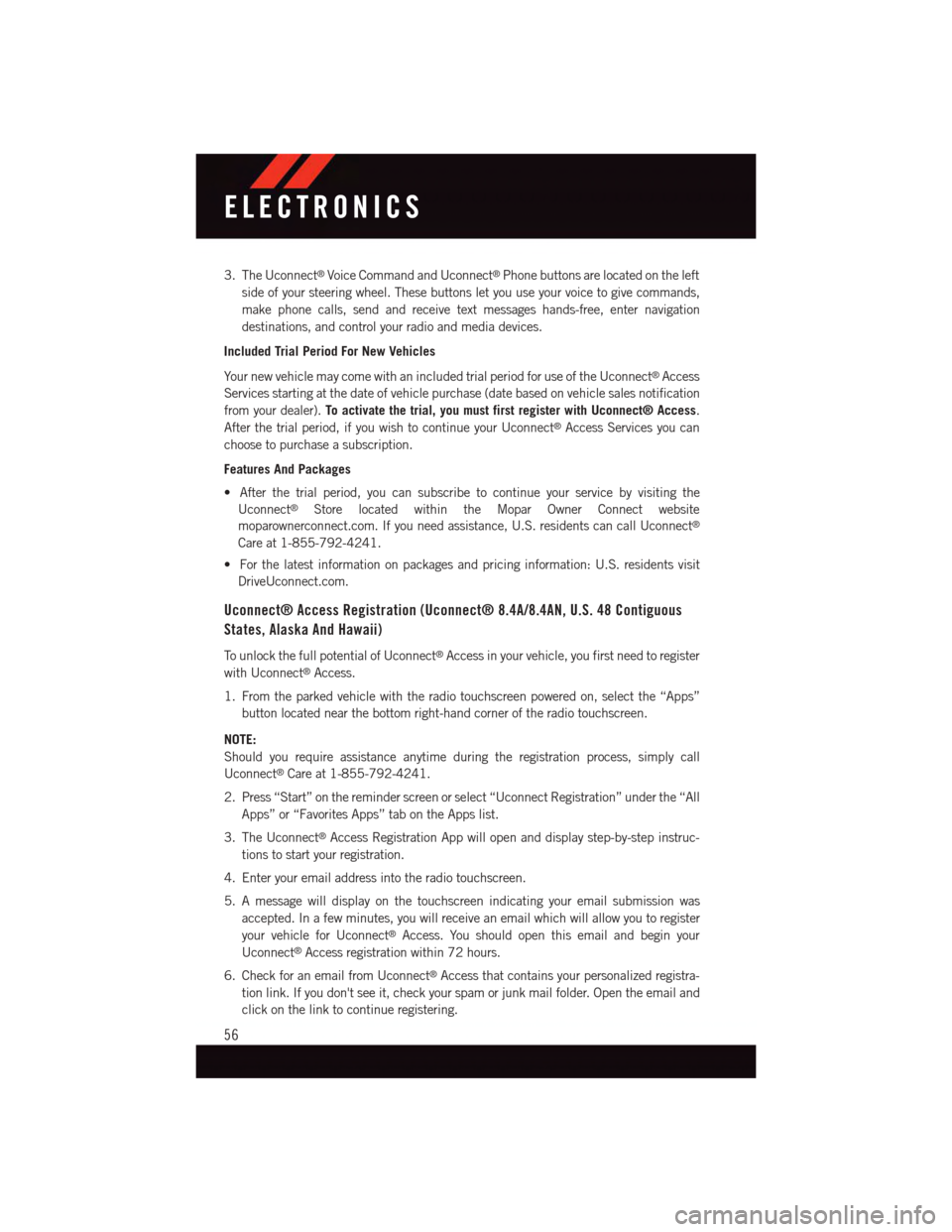
Uconnect® Access Registration (Uconnect® 8.4A/8.4AN, U.S. 48 Contiguous
States, Alaska And Hawaii)
To u n l o c k t h e f u l l p o t e n t i a l o f U c o n n e c t®Access in your vehicle, you first need to register
with Uconnect®Access.
1. From the parked vehicle with the radio touchscreen powered on, select the “Apps”
button located near the bottom right-hand corner of the radio touchscreen.
NOTE:
Should you require assistance anytime during the registration process, simply call
Uconnect®Care at 1-855-792-4241.
2. Press “Start” on the reminder screen or select “Uconnect Registration” under the “All
Apps” or “Favorites Apps” tab on the Apps list.
3. The Uconnect®Access Registration App will open and display step-by-step instruc-
tions to start your registration.
4. Enter your email address into the radio touchscreen.
5. A message will display on the touchscreen indicating your email submission was
accepted. In a few minutes, you will receive an email which will allow you to register
your vehicle for Uconnect®Access. You should open this email and begin your
Uconnect®Access registration within 72 hours.
6. Check for an email from Uconnect®Access that contains your personalized registra-
tion link. If you don't see it, check your spam or junk mail folder. Open the email and
click on the link to continue registering.
ELECTRONICS
56
Page 61 of 220

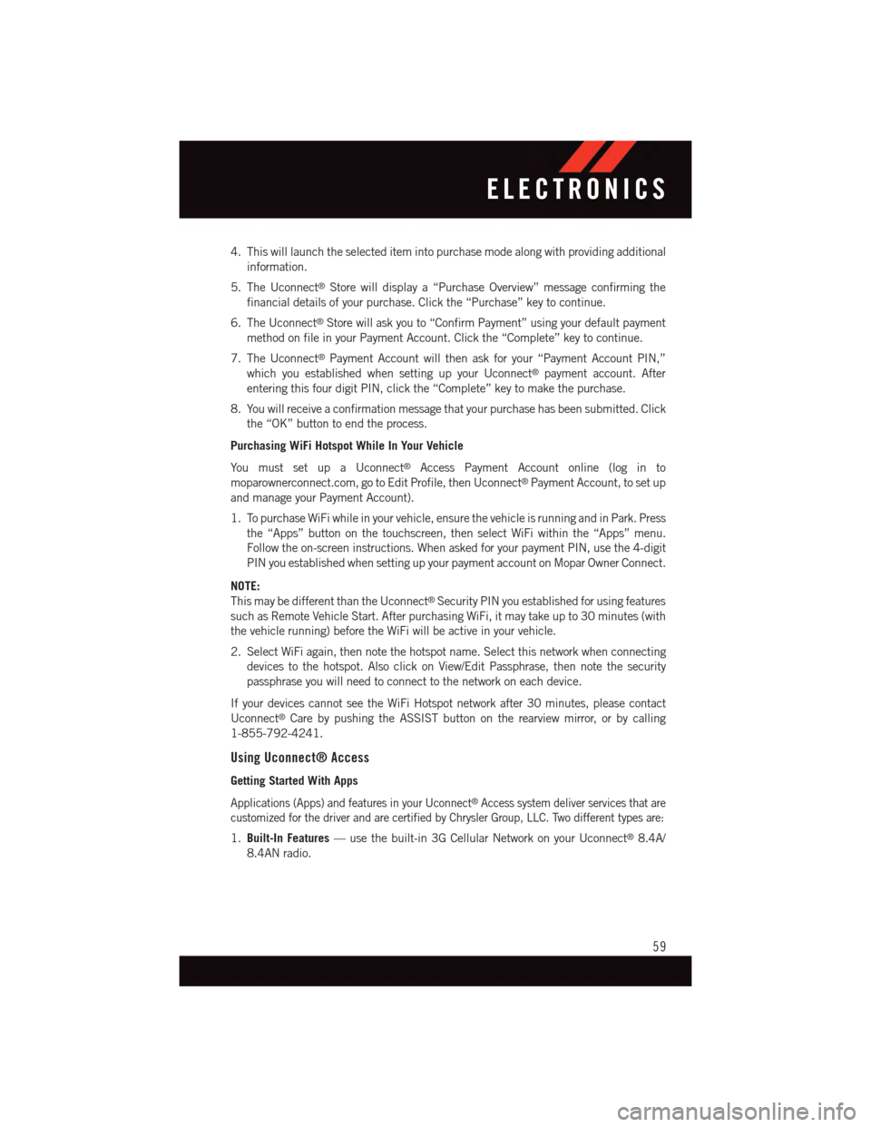
4. This will launch the selected item into purchase mode along with providing additional
information.
5. The Uconnect®Store will display a “Purchase Overview” message confirming the
financial details of your purchase. Click the “Purchase” key to continue.
6. The Uconnect®Store will ask you to “Confirm Payment” using your default payment
method on file in your Payment Account. Click the “Complete” key to continue.
7. The Uconnect®Payment Account will then ask for your “Payment Account PIN,”
which you established when setting up your Uconnect®payment account. After
entering this four digit PIN, click the “Complete” key to make the purchase.
8. You will receive a confirmation message that your purchase has been submitted. Click
the “OK” button to end the process.
Purchasing WiFi Hotspot While In Your Vehicle
Yo u m u s t s e t u p a U c o n n e c t®Access Payment Account online (log in to
moparownerconnect.com, go to Edit Profile, then Uconnect®Payment Account, to set up
and manage your Payment Account).
1. To purchase WiFi while in your vehicle, ensure the vehicle is running and in Park. Press
the “Apps” button on the touchscreen, then select WiFi within the “Apps” menu.
Follow the on-screen instructions. When asked for your payment PIN, use the 4-digit
PIN you established when setting up your payment account on Mopar Owner Connect.
NOTE:
This may be different than the Uconnect®Security PIN you established for using features
such as Remote Vehicle Start. After purchasing WiFi, it may take up to 30 minutes (with
the vehicle running) before the WiFi will be active in your vehicle.
2. Select WiFi again, then note the hotspot name. Select this network when connecting
devices to the hotspot. Also click on View/Edit Passphrase, then note the security
passphrase you will need to connect to the network on each device.
If your devices cannot see the WiFi Hotspot network after 30 minutes, please contact
Uconnect®Care by pushing the ASSIST button on the rearview mirror, or by calling
1-855-792-4241.
Using Uconnect® Access
Getting Started With Apps
Applications (Apps) and features in your Uconnect®Access system deliver services that are
customized for the driver and are certified by Chrysler Group, LLC. Two different types are:
1.Built-In Features—usethebuilt-in3GCellularNetworkonyourUconnect®8.4A/
8.4AN radio.
ELECTRONICS
59
Page 134 of 220

UNIVERSAL GARAGE DOOR OPENER (HomeLink®)
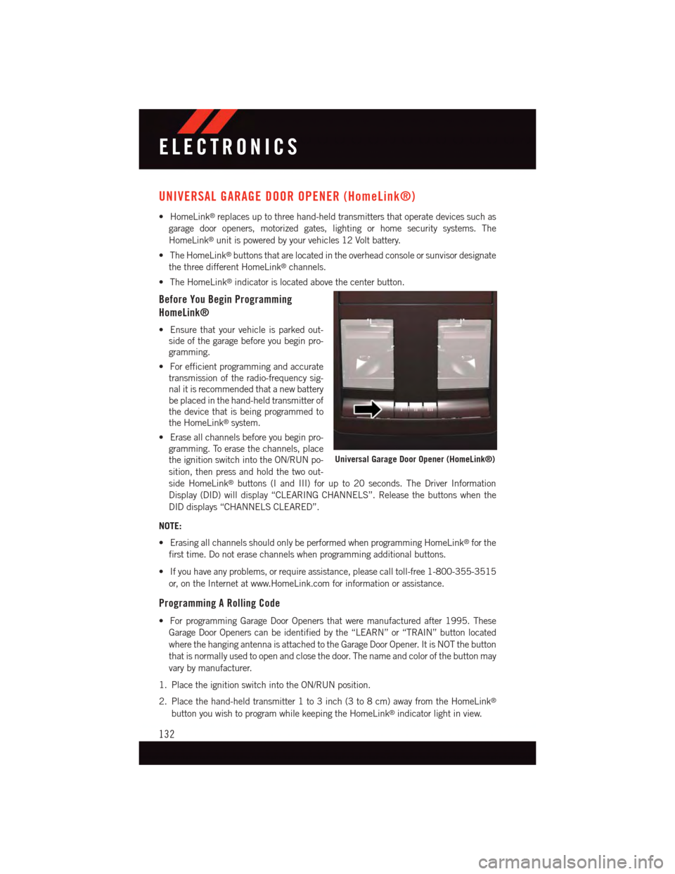
•HomeLink®replaces up to three hand-held transmitters that operate devices such as
garage door openers, motorized gates, lighting or home security systems. The
HomeLink®unit is powered by your vehicles 12 Volt battery.
•TheHomeLink®buttons that are located in the overhead console or sunvisor designate
the three different HomeLink®channels.
•TheHomeLink®indicator is located above the center button.
Before You Begin Programming
HomeLink®
•Ensurethatyourvehicleisparkedout-
side of the garage before you begin pro-
gramming.
•Forefficientprogrammingandaccurate
transmission of the radio-frequency sig-
nal it is recommended that a new battery
be placed in the hand-held transmitter of
the device that is being programmed to
the HomeLink®system.
•Eraseallchannelsbeforeyoubeginpro-
gramming. To erase the channels, place
the ignition switch into the ON/RUN po-
sition, then press and hold the two out-
side HomeLink®buttons (I and III) for up to 20 seconds. The Driver Information
Display (DID) will display “CLEARING CHANNELS”. Release the buttons when the
DID displays “CHANNELS CLEARED”.
NOTE:
•ErasingallchannelsshouldonlybeperformedwhenprogrammingHomeLink®for the
first time. Do not erase channels when programming additional buttons.
•Ifyouhaveanyproblems,orrequireassistance,pleasecalltoll-free1-800-355-3515
or, on the Internet at www.HomeLink.com for information or assistance.
Programming A Rolling Code
•ForprogrammingGarageDoorOpenersthatweremanufacturedafter1995.These
Garage Door Openers can be identified by the “LEARN” or “TRAIN” button located
where the hanging antenna is attached to the Garage Door Opener. It is NOT the button
that is normally used to open and close the door. The name and color of the button may
vary by manufacturer.
1. Place the ignition switch into the ON/RUN position.
2. Place the hand-held transmitter 1 to 3 inch (3 to 8 cm) away from the HomeLink®
button you wish to program while keeping the HomeLink®indicator light in view.
Universal Garage Door Opener (HomeLink®)
ELECTRONICS
132
Page 162 of 220

5. Uncoil the Power Plug (8) and insert the plug into the vehicle’s 12 Volt power outlet.
6. Do not remove foreign objects (e.g., screws or nails) from the tire.
(C) Injecting Tire Service Kit Sealant Into The Deflated Tire:
Always start the engine before turning ON the Tire Service Kit.
NOTE:
Manual transmission vehicles must have the parking brake engaged and the shift lever in
NEUTRAL.
After pressing the Power Button (4), the sealant (white fluid) will flow from the Sealant
Bottle (1) through the Sealant Hose (6) and into the tire.
NOTE:
Sealant may leak out through the puncture in the tire.
If the sealant (white fluid) does not flow within0–10seconds through the Sealant Hose (6):
1. Press the Power Button (4) to turn Off the Tire Service Kit. Disconnect the Sealant
Hose (6) from the valve stem. Make sure the valve stem is free of debris. Reconnect the
Sealant Hose (6) to the valve stem. Check that the Mode Select Knob (5) is in the
Sealant Mode position and not Air Mode. Press the Power Button (4) to turn On the Tire
Service Kit.
2. Connect the Power Plug (8) to a different 12 Volt power outlet in your vehicle or
another vehicle, if available. Make sure the engine is running before turning ON the
Ti r e S e r v i c e K i t .
3. The Sealant Bottle (1) may be empty due to previous use. Call for assistance.
NOTE:
If the Mode Select Knob (5) is on Air Mode and the pump is operating, air will dispense
from the Air Pump Hose (7) only, not the Sealant Hose (6).
If the sealant (white fluid) does flow through the Sealant Hose (6):
1. Continue to operate the pump until sealant is no longer flowing through the hose
(typically takes 30 - 70 seconds). As the sealant flows through the Sealant Hose (6),
the Pressure Gauge (3) can read as high as 70 psi (4.8 Bar). The Pressure Gauge (3)
will decrease quickly from approximately 70 psi (4.8 Bar) to the actual tire pressure
when the Sealant Bottle (1) is empty.
2. The pump will start to inject air into the tire immediately after the Sealant Bottle (1)
is empty. Continue to operate the pump and inflate the tire to the pressure indicated
on the tire pressure label on the driver-side latch pillar (recommended pressure).
Check the tire pressure by looking at the Pressure Gauge (3).
WHAT TO DO IN EMERGENCIES
160
Page 203 of 220

Cavity Cartridge FuseMini-FuseDescription
23—10 Amp Red Fuel Door/DiagnosticPort
24—15 Amp Blue Integrated Center Stack–LD/LX
25—10 Amp Red Tire Pressure Monitor
26
—15 Amp Blue – LD/LX25 Amp Clear – LA30 Amp Green – LA6.2L Supercharged
Tr a n s m i s s i o n / E l e c -tronic Shift Module(LD/LX)Fuel Pump (LA)Fuel Pump (LA 6.2LSupercharged)
27—25 Amp Clear Amplifier / Spare – IfEquipped
31—25 Amp Breaker Power Seats
32—15 Amp Blue HVAC Module/Cluster
33
—15 Amp Blue Ignition Switch/RF hubModule/Steering Col-umn Lock-LX IfEquipped
34—10 Amp Red Steering ColumnModule/Clock/Spare –Police
35—5AmpTan BatterySensor
36—15 Amp Blue Electronic ExhaustValve – If Equipped
37—20 Amp Yellow Radio
38
—10 Amp Red – LD/LX20 Amp Yellow – LADual USB Port(LD/LX)Power Outlet InsideArm Rest (LA)
40——Fuse — Spare
41——Fuse — Spare
4230 Amp Pink—Rear Defrost
43—20 Amp Yellow Rear Heated Seats/Steering Wheel
44—10 Amp Red Park Assist / Blind Spot/RearViewCamera
45—15 Amp Blue Cluster / Rearview Mir-ror / Compass (LDLX)/Humidity Sensor
46——Fuse — Spare
47
—10 Amp Red Adaptive Front Lighting/AutoHighBEAM/DayTi m e R u n n i n g L a m p s -If Equipped
MAINTAINING YOUR VEHICLE
201