Page 209 of 575

Wind Buffeting
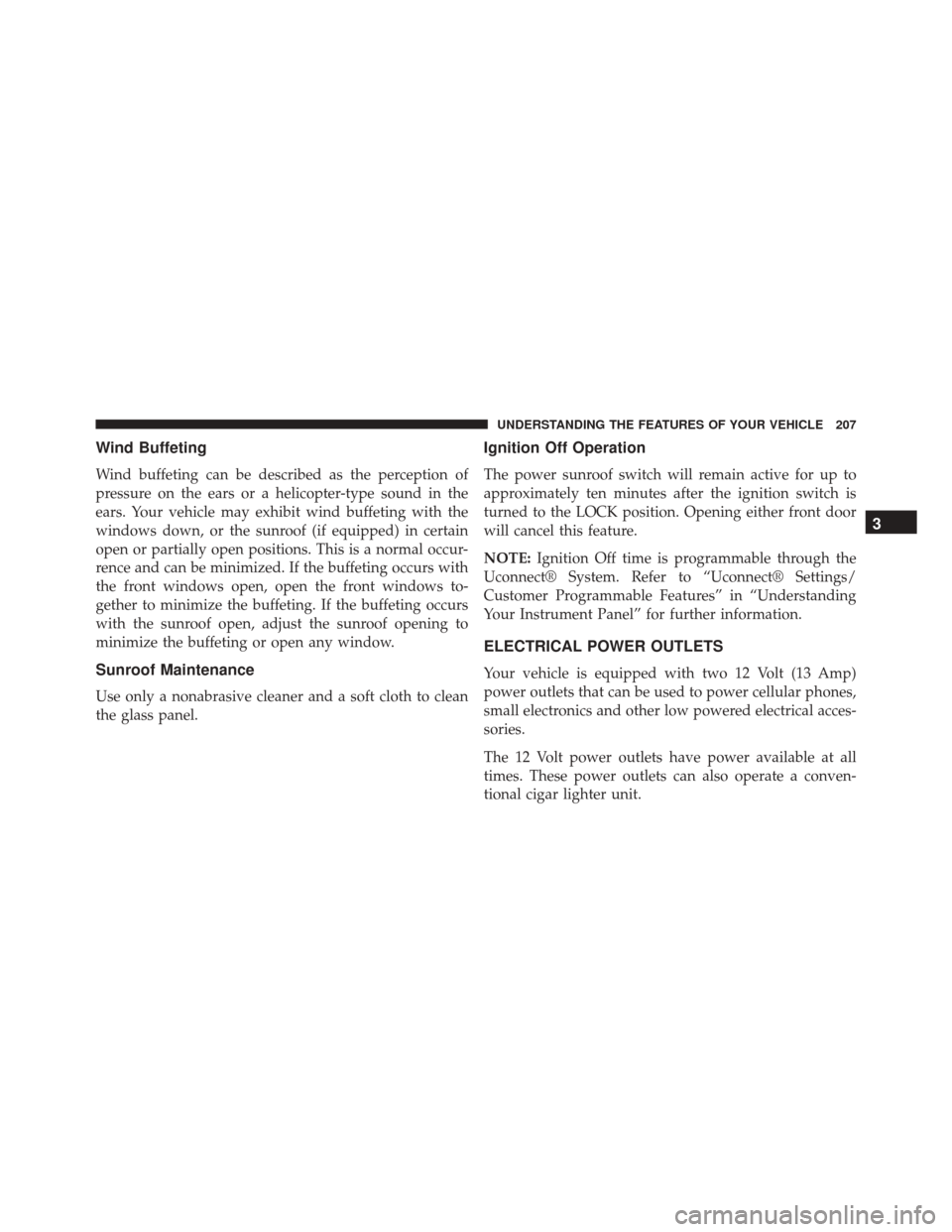
Wind buffeting can be described as the perception of
pressure on the ears or a helicopter-type sound in the
ears. Your vehicle may exhibit wind buffeting with the
windows down, or the sunroof (if equipped) in certain
open or partially open positions. This is a normal occur-
rence and can be minimized. If the buffeting occurs with
the front windows open, open the front windows to-
gether to minimize the buffeting. If the buffeting occurs
with the sunroof open, adjust the sunroof opening to
minimize the buffeting or open any window.
Sunroof Maintenance
Use only a nonabrasive cleaner and a soft cloth to clean
the glass panel.
Ignition Off Operation
The power sunroof switch will remain active for up to
approximately ten minutes after the ignition switch is
turned to the LOCK position. Opening either front door
will cancel this feature.
NOTE:Ignition Off time is programmable through the
Uconnect® System. Refer to “Uconnect® Settings/
Customer Programmable Features” in “Understanding
Your Instrument Panel” for further information.
ELECTRICAL POWER OUTLETS
Your vehicle is equipped with two 12 Volt (13 Amp)
power outlets that can be used to power cellular phones,
small electronics and other low powered electrical acces-
sories.
The 12 Volt power outlets have power available at all
times. These power outlets can also operate a conven-
tional cigar lighter unit.
3
UNDERSTANDING THE FEATURES OF YOUR VEHICLE 207
Page 269 of 575

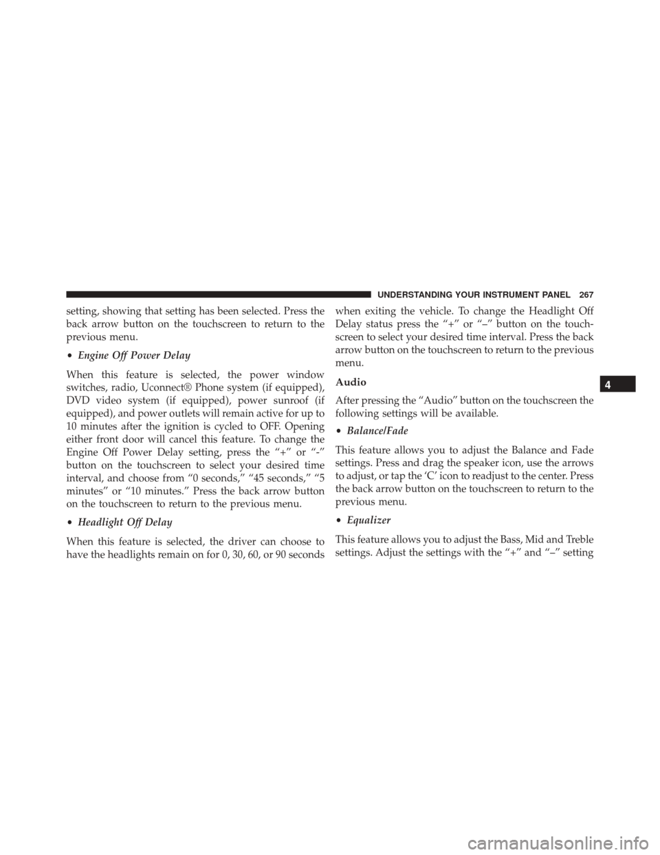
setting, showing that setting has been selected. Press the
back arrow button on the touchscreen to return to the
previous menu.
•Engine Off Power Delay
When this feature is selected, the power window
switches, radio, Uconnect® Phone system (if equipped),
DVD video system (if equipped), power sunroof (if
equipped), and power outlets will remain active for up to
10 minutes after the ignition is cycled to OFF. Opening
either front door will cancel this feature. To change the
Engine Off Power Delay setting, press the “+” or “-”
button on the touchscreen to select your desired time
interval, and choose from “0 seconds,” “45 seconds,” “5
minutes” or “10 minutes.” Press the back arrow button
on the touchscreen to return to the previous menu.
• Headlight Off Delay
When this feature is selected, the driver can choose to
have the headlights remain on for 0, 30, 60, or 90 seconds when exiting the vehicle. To change the Headlight Off
Delay status press the “+” or “–” button on the touch-
screen to select your desired time interval. Press the back
arrow button on the touchscreen to return to the previous
menu.
Audio
After pressing the “Audio” button on the touchscreen the
following settings will be available.
•
Balance/Fade
This feature allows you to adjust the Balance and Fade
settings. Press and drag the speaker icon, use the arrows
to adjust, or tap the ‘C’ icon to readjust to the center. Press
the back arrow button on the touchscreen to return to the
previous menu.
• Equalizer
This feature allows you to adjust the Bass, Mid and Treble
settings. Adjust the settings with the “+” and “–” setting
4
UNDERSTANDING YOUR INSTRUMENT PANEL 267
Page 511 of 575
CavityCartridge Fuse Mini-FuseDescription
2 60 Amp Yellow —Front PDC Feed #1
3 — —Fuse – Spare
4 60 Amp Yellow —Front PDC Feed #2
5 30 Amp Pink —Sunroof / Dome Lamp –
Police
6 40 Amp Green —Exterior Lighting #1
7 40 Amp Green —Exterior Lighting #2
8 30 Amp Pink —Interior Lighting
9 40 Amp Green —Power Locks
10 30 Amp Pink —Driver Door Control
Module
11 30 Amp Pink —Passenger Door Control
Module
7
MAINTAINING YOUR VEHICLE 509
Page 517 of 575
CavityCartridge Fuse Mini-FuseDescription
61 —20 Amp Yellow Cigar Lighter (LA) – If
Equipped
62 ——Fuse — Spare
63 ——Fuse — Spare
64 —25 Amp Breaker Rear Windows (LD/LX)
65 —10 Amp Red Airbag Module
66 ——Fuse — Spare
67 —10 Amp Red Rain and Light Sensor/
Sunroof
68 —10 Amp Red Dual USB Power Outlet –
R/A Sense (LD/LX) Rear
Sunshade (LD/LX)
69 ——Fuse — Spare
70 ——Fuse — Spare
7
MAINTAINING YOUR VEHICLE 515
Page 566 of 575

Overheating, Engine...................... .438
Owner’s Manual (Operator Manual) ..........4,548
Paint Care ............................. .496
Panic Alarm ..............................24
Parking Brake ........................... .382
ParkSense® System, Rear ....................183
Passing Light ........................... .140
Performance ......................... .240, 274
Pets ....................................89
Placard, Tire and Loading Information ..........404
Power Brakes .............................. .385
Deck Lid Release ........................39
Distribution Center (Fuses) ................508
Door Locks ............................31
Mirrors ..............................110
Outlet (Auxiliary Electrical Outlet) ...........207
Seats ............................... .122Sunroof
............................. .204
Tilt/Telescoping Steering Column ............149
Windows ..............................37
Power Steering Fluid ...................... .525
Pregnant Women and Seat Belts ................50
Pretensioners Seat Belts ..............................50
Programmable Features .....................249
Radial Ply Tires ...........................411
Radiator Cap (Coolant Pressure Cap) ...........489
Radio Operation ......................... .308
Radio Remote Controls .....................307
Radio (Sound Systems) .....................305
Rain Sensitive Wiper System .................146
Rear Camera ........................... .192
Rear Cupholder ..........................211
Rear ParkSense System .....................183
Rear Seat, Folding ........................ .131
564 INDEX
Page 570 of 575

Starting Procedures....................... .341
Steering Column Controls ...................... .139
Column Lock ......................... .148
Tilt Column ....................... .148, 149
Wheel, Heated ........................ .150
Wheel, Tilt ........................ .148, 149
Steering Wheel Audio Controls ...............307
Steering Wheel Mounted Sound System Controls . . .307
Storage ............................... .516
Storage, Vehicle ...................... .319, 516
Storing Your Vehicle ...................... .516
Stuck, Freeing ........................... .455
Sunglasses Storage ....................... .195
Sun Roof .............................. .204
Supplemental Restraint System - Airbag ..........54
Synthetic Engine Oil ...................... .473
System, Remote Starting .....................26 Tachometer
............................. .221
Telescoping Steering Column ..............148, 149
Temperature Control, Automatic (ATC) ..........318
Temperature Gauge, Engine Coolant ............221
Tilt Steering Column ....................148, 149
Time Delay, Headlight ..................... .137
Tire and Loading Information Placard .......403, 404
Tire Markings ........................... .397
Tires............................ .95, 408, 549
Aging (Life of Tires) .....................415
Air Pressure .......................... .408
Chains .............................. .417
General Information .....................408
High Speed ...........................411
Inflation Pressures ...................... .409
Life of Tires .......................... .415
Load Capacity ..................... .403, 404
Pressure Monitor System (TPMS) ............419
Pressure Warning Light .................. .221
568 INDEX
Page 574 of 575

INSTALLATION OF RADIO TRANSMITTING
EQUIPMENT
Special design considerations are incorporated into this
vehicle’s electronic system to provide immunity to radio
frequency signals. Mobile two-way radios and telephone
equipment must be installed properly by trained person-
nel. The following must be observed during installation.
The positive power connection should be made directly
to the battery and fused as close to the battery as possible.
The negative power connection should be made to body
sheet metal adjacent to the negative battery connection.
This connection should not be fused.
Antennas for two-way radios should be mounted on the
roof or the rear area of the vehicle. Care should be used
in mounting antennas with magnet bases. Magnets may
affect the accuracy or operation of the compass on
vehicles so equipped.The antenna cable should be as short as practical and
routed away from the vehicle wiring when possible. Use
only fully shielded coaxial cable.
Carefully match the antenna and cable to the radio to
ensure a low Standing Wave Ratio (SWR).
Mobile radio equipment with output power greater than
normal may require special precautions.
All installations should be checked for possible interfer-
ence between the communications equipment and the
vehicle’s electronic systems.