2015 BMW Z4 SDRIVE35IS engine
[x] Cancel search: enginePage 76 of 289

Tachometer
Never force the engine speed up into the red
warning field, see arrow. In this range, the fuel
supply is interrupted to protect the engine.
Coolant temperature A warning light will come on if the coolant, and
therefore the engine, becomes too hot. In addi‐
tion, a message will appear on the Control Dis‐
play.
Check the coolant level, refer to page 241.
Engine oil temperature▷Cold engine: the pointer is at the low tem‐
perature end. Drive at moderate engine
and vehicle speeds.▷Normal operating temperature: the pointer
is in the middle of the temperature display.▷Hot engine: the pointer is at the high tem‐
perature end. Switch off the engine imme‐
diately and allow it to cool down.
If the engine oil temperature is too high, a mes‐
sage appears on the Control Display.
Check the oil level, refer to page 238.
Fuel gauge
The vehicle inclination may cause the display
to vary.
Notes on refueling, refer to page 224.
Range
After the reserve range is reached:
▷A message is briefly displayed on the Con‐
trol Display.Seite 74ControlsDisplays74
Online Edition for Part no. 01 40 2 954 104 - II/15
Page 77 of 289

▷The remaining range is shown on the com‐
puter.▷When a dynamic driving style is used, such
as when corners are taken rapidly, engine
functions are not ensured.
Below a range of approx. 30 miles/50 km, the
message is displayed continuously.
Refuel promptly
At the latest, refuel at a range of
30 miles/50 km; otherwise, the engine function
is not ensured and damage may occur.◀
Computer Displays in the instrument cluster
Calling up information
Press the button on the turn indicator lever.
The following items of information are dis‐
played in the order listed:
▷Range.▷Average speed.▷Average fuel consumption.▷Current fuel consumption.▷No information.
To set the corresponding units of measure,
units of measure, refer to page 78.
Range
Displays the estimated cruising range available
with the remaining fuel. The range is calculated
based on your driving style over the last
18 miles/30 km and the current fuel supply.
Average speed
Periods in which the vehicle was parked and
the engine was switched off manually are not
included in the average speed calculations.
With the trip computer, refer to page 75, you
can have the average speed displayed for an
additional distance.
To reset the average speed: press the button
on the turn indicator lever for approx. 2 sec‐
onds.
Average fuel consumption
The average fuel consumption is calculated for
the time during which the engine is running.
The average consumption is computed based
on the distance traveled since the last time the
computer was reset.
With the trip computer, refer to page 75, you
can have the average consumption displayed
for an additional distance.
To reset the average consumption: press the
button on the turn indicator lever for ap‐
prox. 2 seconds.
Current fuel consumption Displays the current fuel consumption. This al‐
lows you to see whether your current driving
style is conducive to fuel economy with mini‐
mum exhaust emissions.
Displays on the Control Display
The computer can also be opened via iDrive.1."Vehicle Info"Seite 75DisplaysControls75
Online Edition for Part no. 01 40 2 954 104 - II/15
Page 79 of 289

Settings and information
Operating concept1Button for:▷Selecting the display▷Setting values2Button for:▷Confirming selected display or set val‐
ues▷Calling up computer information 753With the lights switched on: dimming the
instrument lighting 904Calling up Check Control 845Checking the engine oil level 2386Setting the time 787Setting the date 798Viewing service requirement display 80Exiting displays
The external temperature reading and the time
reappear when you press button 2 or if you
make no entries within approx. 15 seconds. If
required, complete the current setting first.Seite 77DisplaysControls77
Online Edition for Part no. 01 40 2 954 104 - II/15
Page 84 of 289

Possible displays1Button for selecting functions2Service requirements3Engine oil4Roadworthiness test5Front brake pads6Rear brake pads7Brake fluidThe sequence of displayed service items may
vary. The data for the next service appointment
is shown first.Seite 82ControlsDisplays82
Online Edition for Part no. 01 40 2 954 104 - II/15
Page 89 of 289

LampsVehicle equipment
This chapter describes all series equipment as
well as country-specific and special equipment
offered for this model series. Therefore, it also
describes equipment that may not be found in
your vehicle, for instance due to the selected
special equipment or the country version. This
also applies to safety-related functions and
systems.
When using the features and systems descri‐
bed here, adhere to local regulations.
At a glance0Lamps off
Daytime running lights1Parking lights and daytime running lights2Low-beam headlights and welcome lights3Automatic headlamp control, daytime run‐
ning lights, welcome lamps, High-beam
Assistant, and Adaptive Light Control
When you open the driver's door with the igni‐
tion switched off, the exterior lighting is auto‐
matically switched off if the light switch is in
position 0, 2, or 3.
Switch on the parking lights if necessary,
switch position 1.
Parking lamps/low beams,
headlamp control
Parking lamps Switch position
: the vehicle lamps light
up on all sides, e.g., for parking.
Do not use the parking lamps for extended pe‐
riods; otherwise, the battery may become dis‐
charged and it would then be impossible to
start the engine.
When parking, it is preferable to switch on the
one-sided roadside parking lamps, refer to
page 89.
Low beams Switch position
with the ignition switched
on: the low beams light up.
Welcome lights When parking the vehicle, leave the switch in
position
or : the parking and interior
lamps light up briefly when the vehicle is un‐
locked.
Activating/deactivating the welcome
lamps
1."Settings"2."Lighting"3."Welcome light"
The setting is stored for the remote control
currently in use.
Seite 87LampsControls87
Online Edition for Part no. 01 40 2 954 104 - II/15
Page 97 of 289

wise, reliable signaling of a flat tire is not en‐
sured. Initialize the system after each correc‐
tion of the tire inflation pressure and after
every tire or wheel change.
System limits Sudden tire damage
Sudden serious tire damage caused by
external influences cannot be indicated in ad‐
vance.◀
A natural, even pressure loss in all four tires
cannot be detected.
The system could be delayed or malfunction in
the following situations:▷When the system has not been initialized.▷When driving on a snowy or slippery road
surface.▷Sporty driving style: slip in the drive
wheels, high lateral acceleration.▷When driving with snow chains.
Status display
The current status of the Flat Tire Monitor can
be displayed on the Control Display, e.g.,
whether or not the FTM is active.
1."Vehicle Info"2."Vehicle status"3. "Flat Tire Monitor"
The status is displayed.
Initialization
The initialization process adopts the set infla‐
tion tire pressures as reference values for the
detection of a flat tire. Initialization is started by
confirming the inflation pressures.
Do not initialize the system when driving with
snow chains.
1."Vehicle Info"2."Vehicle status"3. "Reset"4.Start the engine - do not drive away.5.Start the initialization with "Reset".6.Drive away.
The initialization is completed while driving,
which can be interrupted at any time.
The initialization automatically continues when
driving resumes.
Indication of a flat tire The warning lights come on in yellowand red. A message appears on the
Control Display. In addition, a signal
sounds.
There is a flat tire or a major loss in tire inflation
pressure.
1.Reduce your speed and stop cautiously.
Avoid sudden braking and steering maneu‐
vers.2.Check whether the vehicle is fitted with
regular tires or run-flat tires.
Run-flat tires, refer to page 234, are la‐
beled with a circular symbol containing the
letters RSC marked on the tire sidewall.
Do not continue driving without run-flat
tires
Do not continue driving if the vehicle is not
equipped with run-flat tires; continued driving
may result in serious accidents.◀
When a flat tire is indicated, DSC Dynamic Sta‐
bility Control is switched on if necessary.
Actions in the event of a flat tire Normal tires
1.Identify the damaged tire.
Do this by checking the air pressure in all
four tires.
If the tire inflation pressure in all four tires
is correct, the Flat Tire Monitor may not
have been initialized. In this case, initialize
the system.Seite 95SafetyControls95
Online Edition for Part no. 01 40 2 954 104 - II/15
Page 99 of 289
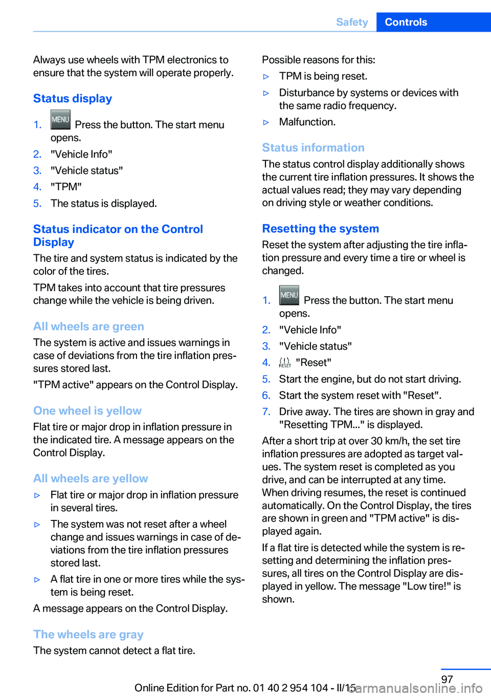
Always use wheels with TPM electronics to
ensure that the system will operate properly.
Status display1. Press the button. The start menu
opens.2."Vehicle Info"3."Vehicle status"4."TPM"5.The status is displayed.
Status indicator on the Control
Display
The tire and system status is indicated by the
color of the tires.
TPM takes into account that tire pressures
change while the vehicle is being driven.
All wheels are green
The system is active and issues warnings in
case of deviations from the tire inflation pres‐
sures stored last.
"TPM active" appears on the Control Display.
One wheel is yellow Flat tire or major drop in inflation pressure in
the indicated tire. A message appears on the
Control Display.
All wheels are yellow
▷Flat tire or major drop in inflation pressure
in several tires.▷The system was not reset after a wheel
change and issues warnings in case of de‐
viations from the tire inflation pressures
stored last.▷A flat tire in one or more tires while the sys‐
tem is being reset.
A message appears on the Control Display.
The wheels are gray The system cannot detect a flat tire.
Possible reasons for this:▷TPM is being reset.▷Disturbance by systems or devices with
the same radio frequency.▷Malfunction.
Status information
The status control display additionally shows
the current tire inflation pressures. It shows the actual values read; they may vary depending
on driving style or weather conditions.
Resetting the system
Reset the system after adjusting the tire infla‐
tion pressure and every time a tire or wheel is
changed.
1. Press the button. The start menu
opens.2."Vehicle Info"3."Vehicle status"4. "Reset"5.Start the engine, but do not start driving.6.Start the system reset with "Reset".7.Drive away. The tires are shown in gray and
"Resetting TPM..." is displayed.
After a short trip at over 30 km/h, the set tire
inflation pressures are adopted as target val‐
ues. The system reset is completed as you
drive, and can be interrupted at any time.
When driving resumes, the reset is continued
automatically. On the Control Display, the tires
are shown in green and "TPM active" is dis‐
played again.
If a flat tire is detected while the system is re‐
setting and determining the inflation pres‐
sures, all tires on the Control Display are dis‐
played in yellow. The message "Low tire!" is
shown.
Seite 97SafetyControls97
Online Edition for Part no. 01 40 2 954 104 - II/15
Page 103 of 289

Driving stability control systemsVehicle equipmentThis chapter describes all series equipment as
well as country-specific and special equipment
offered for this model series. Therefore, it also
describes equipment that may not be found in
your vehicle, for instance due to the selected
special equipment or the country version. This
also applies to safety-related functions and
systems.
When using the features and systems descri‐
bed here, adhere to local regulations.
Antilock Brake System ABS ABS prevents locking of the wheels during
braking.
The vehicle remains steerable even during full
brake applications, thus increasing active
safety.
ABS is operational every time you start the en‐
gine.
Electronic brake-force
distribution
The system controls the brake pressure in the
rear wheels to ensure stable braking behavior.
Dynamic Brake Control DBC
When you apply the brakes rapidly, this system automatically produces the maximum braking
force boost. It thus helps to achieve the short‐
est possible braking distance during full brak‐
ing. This system utilizes all of the benefits pro‐
vided by ABS.
Do not reduce the pressure on the brake pedal
for the duration of the full braking.Dynamic Stability Control
DSC
The concept DSC prevents traction loss in the driving
wheels when driving away and accelerating.
DSC also recognizes unstable vehicle condi‐
tions, such as fishtailing or nose-diving. Sub‐
ject to physical limits, DSC helps to keep the
vehicle on a steady course by reducing engine
speed and by applying brakes to the individual
wheels.
Adjust your driving style to the situation
An appropriate driving style is always the
responsibility of the driver.
The laws of physics cannot be repealed, even
with DSC.
Therefore, do not reduce the additional safety
margin by driving in a risky manner.◀
Activating/deactivating DSC DSC can be deactivated/activated via the DSC
OFF program of the Dynamic Driving Control,
refer to page 102.
For better control The DSC indicator lamp flashes: DSC
is controlling the drive forces and brake
forces.
The DSC indicator lamp lights up: DSC has
failed.Seite 101Driving stability control systemsControls101
Online Edition for Part no. 01 40 2 954 104 - II/15