2015 BMW Z4 SDRIVE28I side lights
[x] Cancel search: side lightsPage 96 of 289

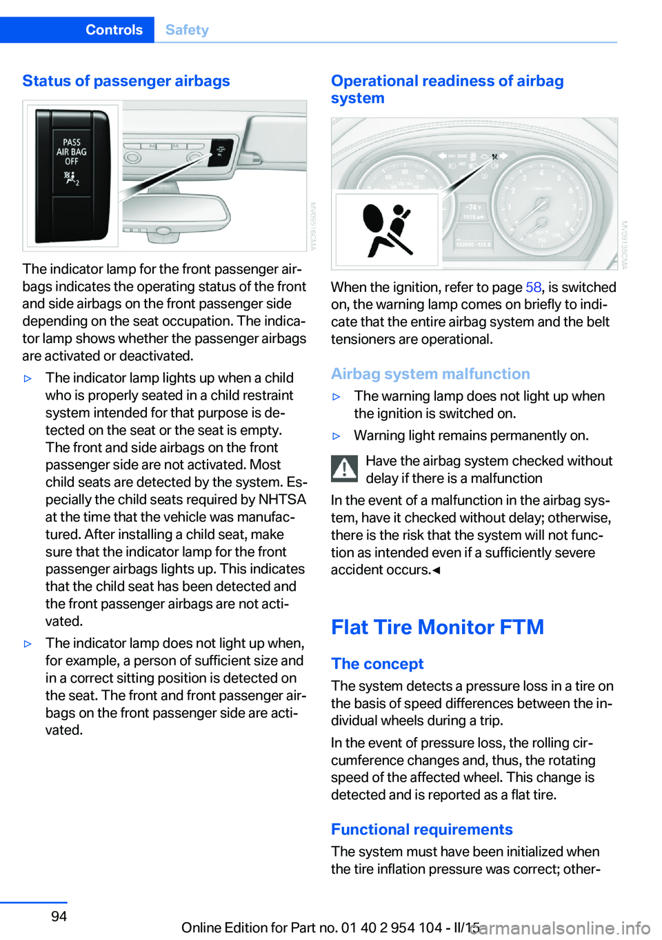
Status of passenger airbags
The indicator lamp for the front passenger air‐
bags indicates the operating status of the front
and side airbags on the front passenger side
depending on the seat occupation. The indica‐
tor lamp shows whether the passenger airbags
are activated or deactivated.
▷The indicator lamp lights up when a child
who is properly seated in a child restraint
system intended for that purpose is de‐
tected on the seat or the seat is empty.
The front and side airbags on the front
passenger side are not activated. Most
child seats are detected by the system. Es‐
pecially the child seats required by NHTSA
at the time that the vehicle was manufac‐
tured. After installing a child seat, make
sure that the indicator lamp for the front
passenger airbags lights up. This indicates
that the child seat has been detected and
the front passenger airbags are not acti‐
vated.▷The indicator lamp does not light up when,
for example, a person of sufficient size and
in a correct sitting position is detected on
the seat. The front and front passenger air‐
bags on the front passenger side are acti‐
vated.Operational readiness of airbag
system
When the ignition, refer to page 58, is switched
on, the warning lamp comes on briefly to indi‐
cate that the entire airbag system and the belt
tensioners are operational.
Airbag system malfunction
▷The warning lamp does not light up when
the ignition is switched on.▷Warning light remains permanently on.
Have the airbag system checked without
delay if there is a malfunction
In the event of a malfunction in the airbag sys‐
tem, have it checked without delay; otherwise,
there is the risk that the system will not func‐
tion as intended even if a sufficiently severe
accident occurs.◀
Flat Tire Monitor FTM The conceptThe system detects a pressure loss in a tire on
the basis of speed differences between the in‐
dividual wheels during a trip.
In the event of pressure loss, the rolling cir‐
cumference changes and, thus, the rotating
speed of the affected wheel. This change is
detected and is reported as a flat tire.
Functional requirements
The system must have been initialized when
the tire inflation pressure was correct; other‐
Seite 94ControlsSafety94
Online Edition for Part no. 01 40 2 954 104 - II/15
Page 97 of 289

wise, reliable signaling of a flat tire is not en‐
sured. Initialize the system after each correc‐
tion of the tire inflation pressure and after
every tire or wheel change.
System limits Sudden tire damage
Sudden serious tire damage caused by
external influences cannot be indicated in ad‐
vance.◀
A natural, even pressure loss in all four tires
cannot be detected.
The system could be delayed or malfunction in
the following situations:▷When the system has not been initialized.▷When driving on a snowy or slippery road
surface.▷Sporty driving style: slip in the drive
wheels, high lateral acceleration.▷When driving with snow chains.
Status display
The current status of the Flat Tire Monitor can
be displayed on the Control Display, e.g.,
whether or not the FTM is active.
1."Vehicle Info"2."Vehicle status"3. "Flat Tire Monitor"
The status is displayed.
Initialization
The initialization process adopts the set infla‐
tion tire pressures as reference values for the
detection of a flat tire. Initialization is started by
confirming the inflation pressures.
Do not initialize the system when driving with
snow chains.
1."Vehicle Info"2."Vehicle status"3. "Reset"4.Start the engine - do not drive away.5.Start the initialization with "Reset".6.Drive away.
The initialization is completed while driving,
which can be interrupted at any time.
The initialization automatically continues when
driving resumes.
Indication of a flat tire The warning lights come on in yellowand red. A message appears on the
Control Display. In addition, a signal
sounds.
There is a flat tire or a major loss in tire inflation
pressure.
1.Reduce your speed and stop cautiously.
Avoid sudden braking and steering maneu‐
vers.2.Check whether the vehicle is fitted with
regular tires or run-flat tires.
Run-flat tires, refer to page 234, are la‐
beled with a circular symbol containing the
letters RSC marked on the tire sidewall.
Do not continue driving without run-flat
tires
Do not continue driving if the vehicle is not
equipped with run-flat tires; continued driving
may result in serious accidents.◀
When a flat tire is indicated, DSC Dynamic Sta‐
bility Control is switched on if necessary.
Actions in the event of a flat tire Normal tires
1.Identify the damaged tire.
Do this by checking the air pressure in all
four tires.
If the tire inflation pressure in all four tires
is correct, the Flat Tire Monitor may not
have been initialized. In this case, initialize
the system.Seite 95SafetyControls95
Online Edition for Part no. 01 40 2 954 104 - II/15
Page 100 of 289

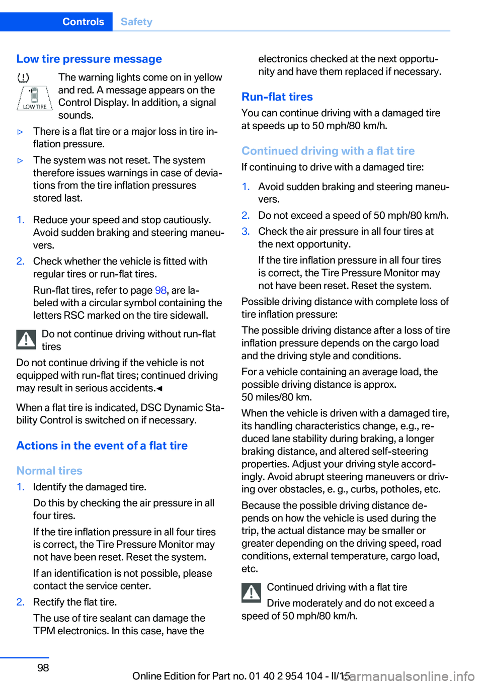
Low tire pressure messageThe warning lights come on in yellow
and red. A message appears on the
Control Display. In addition, a signal
sounds.▷There is a flat tire or a major loss in tire in‐
flation pressure.▷The system was not reset. The system
therefore issues warnings in case of devia‐
tions from the tire inflation pressures
stored last.1.Reduce your speed and stop cautiously.
Avoid sudden braking and steering maneu‐
vers.2.Check whether the vehicle is fitted with
regular tires or run-flat tires.
Run-flat tires, refer to page 98, are la‐
beled with a circular symbol containing the
letters RSC marked on the tire sidewall.
Do not continue driving without run-flat
tires
Do not continue driving if the vehicle is not
equipped with run-flat tires; continued driving
may result in serious accidents.◀
When a flat tire is indicated, DSC Dynamic Sta‐
bility Control is switched on if necessary.
Actions in the event of a flat tire Normal tires
1.Identify the damaged tire.
Do this by checking the air pressure in all
four tires.
If the tire inflation pressure in all four tires
is correct, the Tire Pressure Monitor may
not have been reset. Reset the system.
If an identification is not possible, please
contact the service center.2.Rectify the flat tire.
The use of tire sealant can damage the
TPM electronics. In this case, have theelectronics checked at the next opportu‐
nity and have them replaced if necessary.
Run-flat tires
You can continue driving with a damaged tire
at speeds up to 50 mph/80 km/h.
Continued driving with a flat tire If continuing to drive with a damaged tire:
1.Avoid sudden braking and steering maneu‐
vers.2.Do not exceed a speed of 50 mph/80 km/h.3.Check the air pressure in all four tires at
the next opportunity.
If the tire inflation pressure in all four tires
is correct, the Tire Pressure Monitor may
not have been reset. Reset the system.
Possible driving distance with complete loss of
tire inflation pressure:
The possible driving distance after a loss of tire
inflation pressure depends on the cargo load
and the driving style and conditions.
For a vehicle containing an average load, the
possible driving distance is approx.
50 miles/80 km.
When the vehicle is driven with a damaged tire,
its handling characteristics change, e.g., re‐
duced lane stability during braking, a longer
braking distance, and altered self-steering
properties. Adjust your driving style accord‐
ingly. Avoid abrupt steering maneuvers or driv‐
ing over obstacles, e. g., curbs, potholes, etc.
Because the possible driving distance de‐
pends on how the vehicle is used during the
trip, the actual distance may be smaller or
greater depending on the driving speed, road
conditions, external temperature, cargo load,
etc.
Continued driving with a flat tire
Drive moderately and do not exceed a
speed of 50 mph/80 km/h.
Seite 98ControlsSafety98
Online Edition for Part no. 01 40 2 954 104 - II/15
Page 109 of 289

that the system prerequisites for operation are
currently not met.
Call up Check Control messages, refer to
page 85.
Malfunction The warning light comes on when the
system has failed.
A message appears on the Control
Display. More information, refer to page 84.
Park Distance Control PDC
The concept PDC supports you when parking.
You are alerted that you are slowly approach‐
ing an object behind the vehicle and, if equip‐
ped accordingly, in front of the vehicle by:▷Signal tones.▷A visual display.
Measurement
Measurements are made by ultrasound sen‐
sors in the bumpers.
The range is approx. 6 ft/2 m.
An acoustic warning is first given:
▷By the front sensors and two rear corner
sensors at approx. 24 in/60 cm.▷By the rear middle sensors at approx.
5 ft/1.50 m.
System limits
Check the traffic situation as well
PDC cannot serve as a substitute for the
driver's personal judgment of the traffic situa‐
tion. Check the traffic situation around the ve‐
hicle with your own eyes. Otherwise, an acci‐
dent could result from road users or objects
located outside of the PDC detection range.
Loud noises from outside and inside the vehi‐
cle may prevent you from hearing the PDC's
signal tone.◀
Avoid driving quickly with PDC
Avoid approaching an object quickly.
Avoid driving away quickly while PDC is not yet
active.
For technical reasons, the system may other‐
wise be too late in issuing a warning.◀
Limits of ultrasonic measurement
The detection of objects can reach the physi‐
cal limits of ultrasonic measurement, for in‐
stance:▷With tow bars and trailer hitches.▷With thin or wedge-shaped objects.▷With low objects.▷With objects with corners and sharp edges.
Low objects already displayed, e.g., curbs, can
move into the blind area of the sensors before
or after a continuous tone sounds.
High, protruding objects such as ledges may
not be detected.
False warnings
PDC may issue a warning under the following
conditions even though there is no obstacle
within the detection range:
▷In heavy rain.▷When sensors are very dirty or covered in
ice.▷When sensors are covered in snow.▷On rough road surfaces.▷In large buildings with right angles and
smooth walls, e.g., in underground ga‐
rages.▷In heavy exhaust.▷Due to other ultrasound sources, e.g.,
sweeping machines, high pressure steam
cleaners or neon lights.Seite 107Driving comfortControls107
Online Edition for Part no. 01 40 2 954 104 - II/15
Page 116 of 289

▷Left LED on, automatic recirculated air
control: a sensor detects pollutants in the
outside air. If necessary, the system blocks
the supply of outside air and recirculates
the inside air. As soon as the concentration
of pollutants in the outside air has de‐
creased sufficiently, the system automati‐
cally switches back to outside air supply.▷Right LED on, recirculated air mode: the
supply of outside air into the vehicle is per‐
manently blocked. The system then recir‐
culates the air currently within the vehicle.
Adjusting air flow rate manually
Press the left side of the button to
reduce air flow. Press the right
side of the button to increase it.
The air volume may be reduced automatically
to save battery power. The display remains the
same.
Air distribution, manual
Depending on the selected setting, the air is
directed to the windshield, to the upper body
area, to the knee area and into the footwell.
Adjusting air distribution manually Press the button repeatedly until
the air distribution is set as re‐
quired. The corresponding LED lights up.
The manual air distribution is also switched on
when the AUTO program is deactivated.
Residual heat
The heat stored in the engine is used to heat
the interior.
This function can be switched on
using the right-hand button under
the following conditions:
▷Up to 15 minutes after switching off the
engine.▷When the engine is warm.▷With sufficient battery voltage.▷At an external temperature under
77 ℉/25 ℃.
The middle LED is lit when the function is on.
Defrosting and defogging windows Quickly removes ice and conden‐
sation from the windshield and
front side windows.
For this purpose, also switch on the cooling
function.
Rear window defroster The defroster switches off auto‐
matically after a certain time or
when the hardtop is opened.
Microfilter/activated-charcoal filter
The microfilter traps dust and pollen in the in‐
coming air. The activated-charcoal filter pro‐
vides additional protection by filtering gaseous
pollutants from the outside air. Your service
center replaces this combined filter during rou‐
tine maintenance.
Seite 114ControlsClimate114
Online Edition for Part no. 01 40 2 954 104 - II/15
Page 246 of 289

vehicle's Service and Warranty Information
Booklet for US models, and in the Warranty
and Service Guide Booklet for Canadian mod‐
els. These entries are proof of regular mainte‐
nance.
Socket for OBD Onboard
Diagnosis
Socket for Onboard Diagnosis
The socket for Onboard Diagnosis may
only be used by the service center, by work‐
shops that operate according to the specifica‐
tions of the vehicle manufacturer with appro‐
priately trained personnel, and by other
authorized persons. Otherwise, its use may
lead to vehicle malfunctions.◀
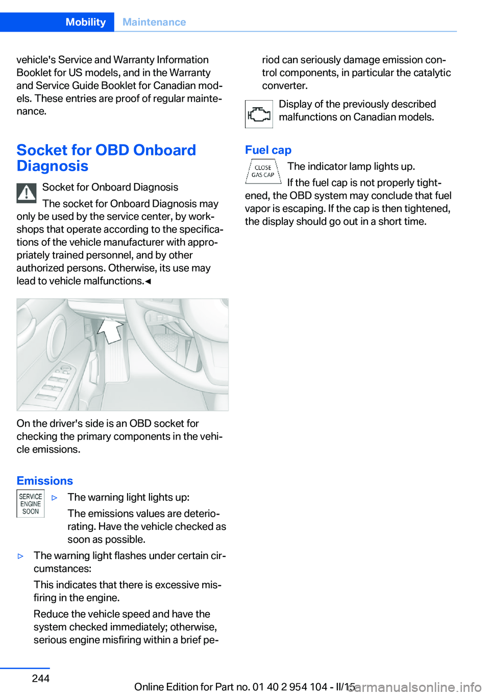
On the driver's side is an OBD socket for
checking the primary components in the vehi‐
cle emissions.
Emissions
▷The warning light lights up:
The emissions values are deterio‐
rating. Have the vehicle checked as
soon as possible.▷The warning light flashes under certain cir‐
cumstances:
This indicates that there is excessive mis‐
firing in the engine.
Reduce the vehicle speed and have the
system checked immediately; otherwise,
serious engine misfiring within a brief pe‐riod can seriously damage emission con‐
trol components, in particular the catalytic
converter.
Display of the previously described
malfunctions on Canadian models.
Fuel cap The indicator lamp lights up.
If the fuel cap is not properly tight‐
ened, the OBD system may conclude that fuel
vapor is escaping. If the cap is then tightened,
the display should go out in a short time.
Seite 244MobilityMaintenance244
Online Edition for Part no. 01 40 2 954 104 - II/15
Page 248 of 289

Use a clean tissue, cloth or something similar,
or hold the bulb by its base.◀
Light-emitting diodes LED
Light-emitting diodes installed behind translu‐
cent lenses serve as the light source for many
of the controls and displays in your vehicle.
These light-emitting diodes, which operate us‐
ing a concept similar to that applied in conven‐
tional lasers, are officially designated as
Class 1 light-emitting diodes.
Do not remove the covers
Do not remove the covers, and never
stare into the unfiltered light for several hours;
otherwise, irritation of the retina could result.◀
Headlight glass
Condensation can form on the inside of the ex‐
ternal lights in cool or humid weather. When
you drive with the lights switched on, the con‐
densation evaporates after a short time. The
headlight glasses do not need to be changed.
If the condensation in the headlights does not
evaporate after trips with the lights switched
on, and the amount of moisture in the head‐
lights increases, for example if water droplets
form, have them checked by your service cen‐
ter.
Headlight setting
Changing the bulbs and lights may influence
the headlight settings. Have the headlight set‐
ting checked by a service center and corrected
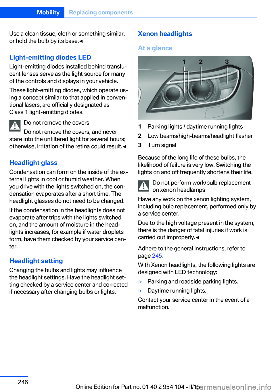
if necessary after changing bulbs or lights.Xenon headlights
At a glance1Parking lights / daytime running lights2Low beams/high-beams/headlight flasher3Turn signal
Because of the long life of these bulbs, the
likelihood of failure is very low. Switching the
lights on and off frequently shortens their life.
Do not perform work/bulb replacement
on xenon headlamps
Have any work on the xenon lighting system,
including bulb replacement, performed only by
a service center.
Due to the high voltage present in the system,
there is the danger of fatal injuries if work is
carried out improperly.◀
Adhere to the general instructions, refer to
page 245.
With Xenon headlights, the following lights are
designed with LED technology:
▷Parking and roadside parking lights.▷Daytime running lights.
Contact your service center in the event of a
malfunction.
Seite 246MobilityReplacing components246
Online Edition for Part no. 01 40 2 954 104 - II/15
Page 257 of 289

Follow the towing instructions
Follow all towing instructions, or vehicle
damage or accidents may occur.◀▷Make sure that the ignition is switched on;
otherwise, the low beams, tail lights, turn
signals, and windshield wipers may be un‐
available.▷Do not tow the vehicle with the rear axle
tilted, as the front wheels could turn.▷When the engine is stopped, there is no
power assist. Consequently, more force
needs to be applied when braking and
steering.▷Larger steering wheel movements are re‐
quired.▷The towing vehicle must not be lighter
than the vehicle being towed; otherwise,
it will not be possible to control the vehicle
response.
Tow truck
Have your vehicle transported with a tow truck
with a so-called lift bar or on a flat bed.
Do not lift the vehicle
Do not lift the vehicle by the tow fitting or
body and chassis parts; otherwise, damage
may result.◀
Towing other vehicles
General information Light towing vehicle
The towing vehicle must not be lighter
than the vehicle being towed; otherwise, it will
not be possible to control the vehicle re‐
sponse.◀
Attaching the tow bar/tow rope correctly
Attach the tow bar or tow rope to the tow
fitting; connecting it to other vehicle parts may
cause damage.◀▷Switch on the hazard warning system, de‐
pending on local regulations.▷If the electrical system has failed, clearly
identify the vehicle being towed by placing
a sign or a warning triangle in the rear win‐
dow.
Tow bar
The tow fittings used should be on the same
side on both vehicles.
Should it prove impossible to avoid mounting
the tow bar at an offset angle, please observe
the following:
▷Maneuvering capability is limited during
cornering.▷The tow bar will generate lateral forces if it
is secured with an offset.
Tow rope
When starting to tow the vehicle, make sure
that the tow rope is taut.
To avoid jerking and the associated stresses
on the vehicle components when towing, al‐
ways use nylon ropes or nylon straps.
Attaching the tow rope correctly
Only secure the tow rope on the tow fit‐
ting; otherwise, damage can occur when it is
secured on other parts of the vehicle.◀
Seite 255Breakdown assistanceMobility255
Online Edition for Part no. 01 40 2 954 104 - II/15