2015 BMW X5M Snow
[x] Cancel search: SnowPage 81 of 255

▷Automatic downshifting and protection
from misshifting even in sequential mode.▷Launch Control.▷Low Speed Assistant.
Selector lever, selector lever positions
Overview
▷R: reverse gear.▷N: neutral.▷ Center position, forward position.▷+: manual upshifting.▷-: manual downshifting.▷D/S: switch between drive mode and se‐
quential mode.
Engaging a selector lever position
Press on the brake pedal and pull or push the
selector lever in the corresponding direction.
As soon as the selector lever is released, it re‐
verts to the center position. In position R, the
selector lever locks.
The engaged selector lever position is dis‐
played in the instrument cluster and on the se‐
lector lever.
If a selector lever position is engaged, the vehi‐
cle may start rolling, after the brake is released,
e.g. on downhill slopes. Thus, drive off immedi‐
ately after releasing the brake.
Use the Slow Speed Assistant for maneuver‐
ing and during stop-and-go traffic.
Low Speed Assistant
The concept
The Low Speed Assistant gives assistance at
very low speeds. The vehicle moves at walking
speed.
This can also be used for rocking the vehicle in
the snow. To do this, switch between reverse
gear and forward gear without stepping on the
brakes in the process.
Activating1.Engage a driving position.2.Briefly tap the accelerator pedal.
The vehicle rolls at minimum speed.
This is possible in 1st and 2nd gear and in re‐
verse gear.
Deactivating
Apply the brakes until the vehicle comes to a
stop.
Flashing display on the selector lever The actually engaged transmission position
can deviate from the selector lever position in
some situations. The display in the selector
lever flashes.
Observe the display in the instrument cluster,
refer to page 82, in these cases.
D Drive mode
In Drive mode, all forward gears are automati‐
cally changed.
Kickdown: for maximum acceleration, e. g. when passing. To do this, depress the acceler‐
ator pedal past the resistance point.
Switch to Sequential mode: shift using the
shift paddles or the selector lever, or push the
selector lever in the D/S direction.
S Sequential mode
Use the shift paddles or the selector lever to
upshift or downshift without letting off the gas.
Seite 81DrivingControls81
Online Edition for Part no. 01 40 2 964 090 - VI/15
Page 85 of 255
M Driving Dynamics Control
The concept The M Driving Dynamics Control affects the
response of the vehicle to accelerator pedal movements.
Programs Response behavior options:▷"Efficient": efficient, comfortable. Minimal
fuel consumption.
Ideal e. g. in city traffic or on snow.▷"Sport": sporty, dynamic.▷"Sport Plus": spontaneous, direct. Maxi‐
mum dynamics.
Selecting a channel
Via M Drive On the Control Display:
1."Settings"2."M Drive 1" or "M Drive 2"3. Select the symbol.4.Select the desired channel.
When M Drive is active, setting is immedi‐
ately applied.
To activate M Drive with the selected settings,
press the corresponding button on the steer‐
ing wheel:
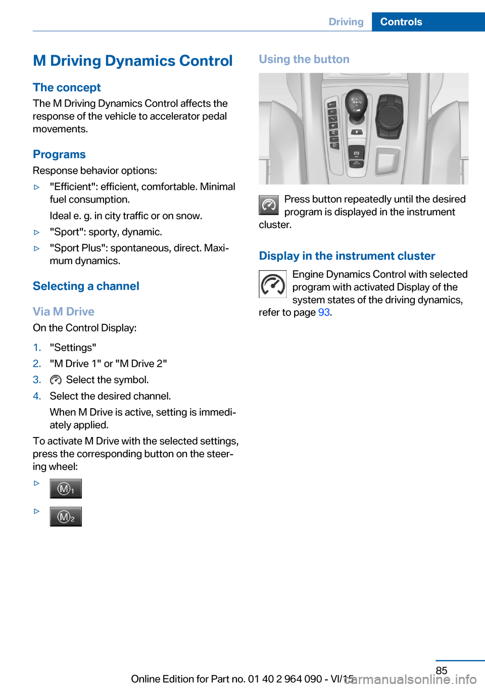
▷▷Using the button
Press button repeatedly until the desired
program is displayed in the instrument
cluster.
Display in the instrument cluster Engine Dynamics Control with selected
program with activated Display of the
system states of the driving dynamics,
refer to page 93.
Seite 85DrivingControls85
Online Edition for Part no. 01 40 2 964 090 - VI/15
Page 96 of 255

If speed limit detection is switched on, it can
be displayed on the info display in the instru‐
ment cluster via the on-board comupter.
Display The following is displayed in the instrument
cluster:
Speed limit detection Current speed limit.
Speed limit detection is not available.
Speed limit detection can also be displayed in
the Head-up Display.
System limits
The system may not be fully functional and
may provide incorrect information in the fol‐
lowing situations:▷In heavy fog, rain or snowfall.▷When signs are concealed by objects.▷When driving very close to the vehicle in
front of you.▷When driving toward bright lights.▷When the windshield behind the interior
rearview mirror is fogged over, dirty or cov‐
ered by a sticker, etc.▷In the event of incorrect detection by the
camera.▷If the speed limits stored in the navigation
system are incorrect.▷In areas not covered by the navigation sys‐
tem.▷When roads differ from the navigation,
such as due to changes in road routing.▷When passing buses or trucks with a
speed sticker.▷If the traffic signs are non-conforming.▷During calibration of the camera immedi‐
ately after vehicle delivery.
Selection lists in the
instrument cluster
The concept Depending on your vehicle's optional features,
the following can be displayed or operated us‐
ing the buttons and the thumbwheel on the
steering wheel as well as the displays in the in‐
strument cluster and the Head-up Display:
▷Current audio source.▷Redial phone feature.▷Turn on voice activation system.
Display
Depending on your vehicle's optional features,
the list in the instrument cluster can differ from
the illustration shown.
Seite 96ControlsDisplays96
Online Edition for Part no. 01 40 2 964 090 - VI/15
Page 115 of 255

ating properly. The TPMS malfunction indica‐
tor is combined with the low tire pressure
telltale. When the system detects a malfunc‐
tion, the telltale will flash for approximately one
minute and then remain continuously illumi‐
nated. This sequence will continue upon sub‐
sequent vehicle start-ups as long as the mal‐
function exists. When the malfunction indicator
is illuminated, the system may not be able to
detect or signal low tire pressure as intended.
TPMS malfunctions may occur for a variety of
reasons, including the installation of replace‐
ment or alternate tires or wheels on the vehicle
that prevent the TPMS from functioning prop‐
erly. Always check the TPMS malfunction tell‐
tale after replacing one or more tires or wheels
on your vehicle to ensure that the replacement
or alternate tires and wheels allow the TPMS
to continue to function properly.
FTM Flat Tire Monitor The conceptThe system detects tire inflation pressure losson the basis of rotation speed differences be‐
tween the individual wheels while driving.
In the event of a tire inflation pressure loss, the
diameter and therefore the rotational speed of
the corresponding wheel changes. This will be
detected and reported as a flat tire.
The system does not measure the actual infla‐
tion pressure in the tires.
Functional requirements
The system must have been initialized when
the tire inflation pressure was correct; other‐
wise, reliable flagging of a flat tire is not as‐
sured. Initialize the system after each correc‐ tion of the tire inflation pressure and after
every tire or wheel change.Status display
The current status of the Flat Tire Monitor can
be displayed on the Control Display, e.g.,
whether or not the FTM is active.
On the Control Display:1."Vehicle info"2."Vehicle status"3. "Flat Tire Monitor (FTM)"
The status is displayed.
Initialization
When initializing the once set inflation tire
pressures serve as reference values in order to
detect a flat tire. Initialization is started by con‐
firming the tire inflation pressures.
Do not initialize the system when driving with
snow chains.
On the Control Display:
1."Vehicle info"2."Vehicle status"3. "Perform reset"4.Start the engine - do not drive off.5.Start the initialization with "Perform reset".6.Drive away.
The initialization is completed while driving,
which can be interrupted at any time.
The initialization automatically continues when
driving resumes.
Indication of a flat tire The yellow warning lamp lights up. A
Check Control message is displayed.
There is a flat tire or a major loss in tire
inflation pressure.
1.Reduce your speed and stop cautiously.
Avoid sudden braking and steering maneu‐
vers.2.Identify the damaged wheel. Do so by
checking the tire inflation pressure usingSeite 115SafetyControls115
Online Edition for Part no. 01 40 2 964 090 - VI/15
Page 116 of 255
the Mobility System. If the tire inflation
pressure in all tires is correct, the Flat Tire
Monitor may not have been initialized. In
this case, initialize the system.3.Repair flat tire with the Mobility System or
replace the damaged wheel.
System limits
A natural, even tire inflation pressure loss in all
four tires will not be recognized. Therefore,
check the tire inflation pressure regularly.
Sudden serious tire damage caused by exter‐
nal circumstances cannot be recognized in ad‐
vance.
The system could be delayed or malfunction in
the following situations:
▷When the system has not been initialized.▷When driving on a snowy or slippery road
surface.▷Sporty driving style: spinning traction
wheels, high lateral acceleration (drifting).▷When driving with snow chains.
Intelligent Safety
The concept
Intelligent Safety enables central operation of
the driver assistance system. Depending on
how the vehicle is equipped, Intelligent Safety
consists of one or more systems that can help
prevent a imminent collision.
▷Front-end collision warning with City Brak‐
ing function, refer to page 117.▷Pedestrian warning, refer to page 119.▷Lane departure warning, refer to
page 125.▷Active Blind Spot Detection, refer to
page 127.Information
WARNING
Indicators and warnings do not relieve
from the personal responsibility. Due to sys‐
tem limits, warnings or reactions of the system
may not be output or they may be output too
late or incorrectly. There is risk of an accident.
Adjust the driving style to the traffic condi‐
tions. Watch traffic closely and actively inter‐
fere in the respective situations.◀
WARNING
Due to system limits, individual functions
can malfunction during tow-starting/towing
with the Intelligent Safety systems activated,
e.g. approach control warning with light brak‐
ing function. There is risk of an accident.
Switch all Intelligent Safety systems off prior to
tow-starting/towing.◀
Overview
Button in the vehicle
Intelligent Safety button
Switching on/off Some Intelligent Safety systems are automati‐
cally active after every departure. Some Intelli‐
gent Safety systems activate according to the
last setting.
Press button briefly:
▷The menu for the intelligent safety
system is displayed. The systemsSeite 116ControlsSafety116
Online Edition for Part no. 01 40 2 964 090 - VI/15
Page 119 of 255
Prewarning
This warning is issued, e.g., when there is the
impending danger of a collision or the distance
to the vehicle ahead is too small.
The driver must intervene actively when there
is a prewarning.
Acute warning with braking function
Acute warning in displayed in case of the immi‐
nent danger of a collision when the vehicle ap‐
proaches another object at a relatively high dif‐
ferential speed.
The driver must intervene actively when there
is an acute warning. If necessary, the driver is
assisted by a minor automatic braking inter‐
vention in a possible risk of collision.
Acute warnings can also be triggered without
previous forewarning.
Braking intervention
The warning prompts the driver himself/herself
to react. During a warning, the maximum brak‐
ing force is used. Premise for the brake boos‐
ter is sufficiently quick and hard stepping on
the brake pedal. The system can assist with some braking intervention if there is risk of a
collision. At low speeds vehicles may thus
come to a complete stop.
The braking intervention is executed only if
DSC Dynamic Stability Control is switched on
and M Dynamic mode MDM is not activated.
The braking intervention can be interrupted by
stepping on the accelerator pedal or by ac‐
tively moving the steering wheel.
Object detection can be restricted. Limitations
of the detection range and functional restric‐
tions are to be considered.
System limits
Detection range
The system's detection potential is limited.Thus a system reaction might not come or
might come late.
E. g. the following situations may not be de‐
tected:▷Slow moving vehicles when you approach
them at high speed.▷Vehicles that suddenly swerve in front of
you, or sharply decelerating vehicles.▷Vehicles with an unusual rear appearance.▷Two-wheeled vehicles ahead of you.
Functional limitations
The system may not be fully functional in the
following situations:
▷In heavy fog, rain, sprayed water or snow‐
fall.▷In tight curves.▷If the driving stability control systems are
limited or deactivated, e.g., DSC OFF.▷If the field of view of the camera in the mir‐
ror is dirty or obscured.▷Up to 10 seconds after the start of the en‐
gine, via the Start/Stop button.▷During calibration of the camera immedi‐
ately after vehicle delivery.▷If there are constant blinding effects be‐
cause of oncoming light, e. g., from the sun
low in the sky.
Warning sensitivity
The more sensitive the warning settings are,
e.g. the warning time, the more warnings are
displayed. However, there may also be an ex‐
cess of false warnings.
Pedestrian warning
Depending on how the vehicle is equipped, the
function warns of an imminent collision with
pedestrians during daytime or nighttime.
The function is subdivided into the following
systems:
Seite 119SafetyControls119
Online Edition for Part no. 01 40 2 964 090 - VI/15
Page 122 of 255
▷Pedestrians outside of the detection range.▷Pedestrians having a body size less than
32 in/80 cm.
Functional limitations
The system may not be fully functional or may
not be available in the following situations:
The system may not be fully functional in the
following situations:
▷In heavy fog, rain, sprayed water or snow‐
fall.▷In tight curves.▷If the driving stability control systems are
deactivated, e.g. DSC OFF.▷If the field of view of the camera or the front
windshield are dirty or covered.▷Up to 10 seconds after the start of the en‐
gine, via the Start/Stop button.▷During calibration of the camera immedi‐
ately after vehicle delivery.▷If there are constant blinding effects be‐
cause of oncoming light, e. g., from the sun
low in the sky.▷When it is dark outside.
Night Vision with Pedestrian
and Animal Detection
The concept Night Vision with pedestrian and animal detec‐
tion is a night vision system.
An infrared camera scans the area in front of
the vehicle and issues a warning if it detects
pedestrians and animals on the street. Warm
objects that are similar in shape to human be‐
ings or animals are detected by the system. If necessary, the heat image can be displayed on
the Control Display.
Heat image
The image shows the heat radiated by objects
in the field of view of the camera.
Warm objects have a light appearance and
cold objects a dark appearance.
The ability to detect an object depends on the
temperature difference between the object
and the background and on the level of heat
radiation emitted by the object. Objects that
are similar in temperature to the environment
or that radiate very little heat are difficult to de‐
tect.
For safety reasons, when driving at speeds
above approx. 3 mph/5 km/h and in low ambi‐
ent light, the image is only displayed when the
low beams are activated.
A still image is displayed at regular intervals for
a fraction of a second.
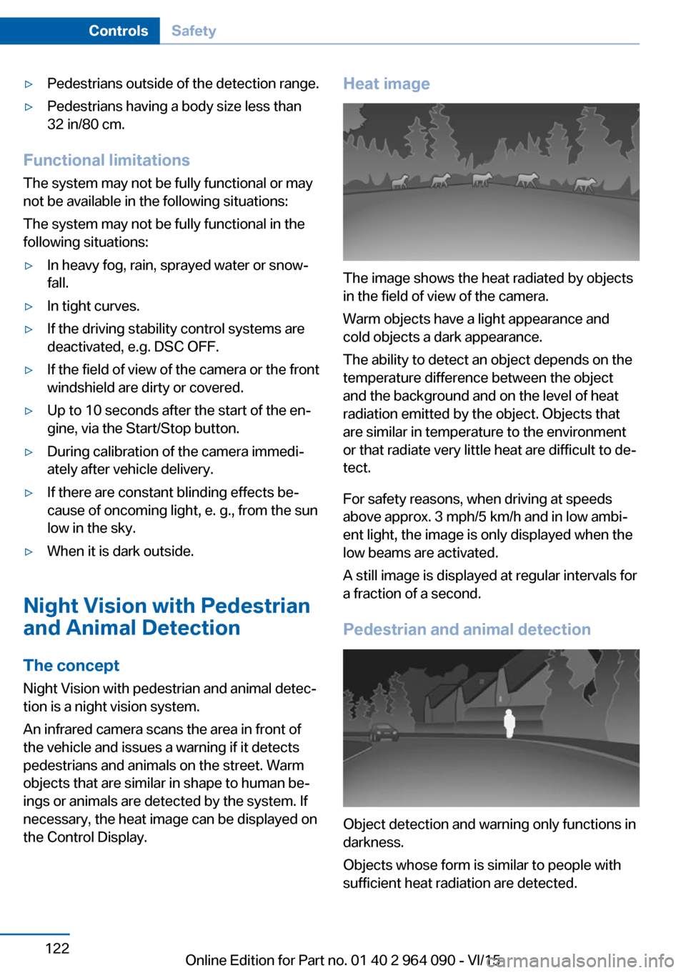
Pedestrian and animal detection
Object detection and warning only functions in
darkness.
Objects whose form is similar to people with
sufficient heat radiation are detected.
Seite 122ControlsSafety122
Online Edition for Part no. 01 40 2 964 090 - VI/15
Page 125 of 255
with the vehicle speed. As the vehicle speed
increases, the area becomes longer and wider,
e.g.
Prewarning The yellow symbol is displayed when a
person is detected in the central area immediately in front of the vehicle.
The yellow symbol is displayed when a person
in the extended area is moving from the right
or left towards the central area.
The displayed symbol can vary with the people
detected.
Intervene actively by braking or make an eva‐
sive maneuver.
When animals are detected, an animal
symbol is displayed. The symbol also
shows the side of the road on which
the animal was detected. Intervene actively by
braking or make an evasive maneuver.
Acute warning The red symbol is displayed and a sig‐
nal sounds.
When animals are detected, an red animal
symbol is displayed with the signal tone.
Red symbol in the instrument cluster.
Intervene immediately by braking or make an
evasive maneuver.
Display in the Head-up Display The warning is displayed simultane‐
ously in the Head-up Display and on
the instrument cluster. The displayed
symbol can vary with the people detected.
When animals are detected, an animal symbol
is displayed.System limits
Basic limits System operation is limited in situations such
as the following:▷On steep hills, in steep depressions or in
tight curves.▷When the camera is dirty or the protective
glass is damaged.▷In heavy fog, rain or snowfall.▷At very high external temperatures.
Limits of pedestrian and animal
detection
In some situations, it may occur that pedes‐
trians are detected as animals or animals as
pedestrians.
Small animals are not detected by the object
detection function, even if they are clearly visi‐
ble in the image.
Limited detection, e.g. in the following circum‐
stances:
▷People or animals who are fully or partially
covered, especially when their heads are
covered.▷People who are not in an upright position,
e.g., lying down.▷Cyclists on unconventional bicycles (e.g.,
recumbent bicycles).▷After physical damage to the system, e.g.,
after an accident.
No display on the rear screen
The image from Night Vision cannot be dis‐
played on the rear screen.
Lane departure warning The concept Starting at a specific speed, this system alerts
you when the vehicle on streets with lane
Seite 125SafetyControls125
Online Edition for Part no. 01 40 2 964 090 - VI/15