2015 BMW X5M tire
[x] Cancel search: tirePage 114 of 255

Required tire inflation pressure check
message
A Check Control message is displayed in the
following situations▷The system has detected a wheel change,
but no reset was done.▷Inflation was not carried out according to
specifications.▷The tire inflation pressure has fallen below
the level of the last confirmation.
In this case:
▷Check the tire pressure and correct as
needed.▷Carry out a reset of the system after a tire
change.
System limits
The system does not function properly if a re‐
set has not been carried out, e.g., a flat tire is
reported though tire inflation pressures are
correct.
The tire inflation pressure depends on the
tire's temperature. Driving or exposure to the
sun will increase the tire's temperature, thus
increasing the tire inflation pressure. The tire
inflation pressure is reduced when the tire
temperature falls again. These circumstances
may cause a warning when temperatures fall
very sharply.
The system cannot indicate sudden serious
tire damage caused by external circumstances.
Malfunction The yellow warning lamp flashes and
then lights up continuously. A Check
Control message is displayed. No flat
tire or loss of tire inflation pressure can be de‐
tected.
Examples and recommendations in the follow‐
ing situations:
▷A wheel without TPM electronics is
mounted: Have it checked by a dealer’sservice center or another qualified service
center or repair shop as needed.▷Malfunction: Have system checked by a
dealer’s service center or another qualified
service center or repair shop.▷TPM was unable to complete the reset.
Reset the system again.▷Interference through systems or devices
with the same radio frequency: After leav‐
ing the area of the interference, the system
automatically becomes active again.
Declaration according to NHTSA/
FMVSS 138 Tire Pressure Monitoring
System
Each tire, including the spare (if provided)
should be checked monthly when cold and in‐
flated to the inflation pressure recommended
by the vehicle manufacturer on the vehicle
placard or tire inflation pressure label. (If your
vehicle has tires of a different size than the size
indicated on the vehicle placard or tire inflation
pressure label, you should determine the
proper tire inflation pressure for those tires.)
As an added safety feature, your vehicle has
been equipped with a tire pressure monitoring
system (TPMS) that illuminates a low tire pres‐
sure telltale when one or more of your tires is
significantly under-inflated. Accordingly, when
the low tire pressure telltale illuminates, you
should stop and check your tires as soon as
possible, and inflate them to the proper pres‐
sure. Driving on a significantly under-inflated
tire causes the tire to overheat and can lead to
tire failure. Under-inflation also reduces fuel ef‐
ficiency and tire tread life, and may affect the
vehicle's handling and stopping ability. Please
note that the TPMS is not a substitute for
proper tire maintenance, and it is the driver's
responsibility to maintain correct tire pressure,
even if under-inflation has not reached the
level to trigger illumination of the TPMS low
tire pressure telltale. Your vehicle has also
been equipped with a TPMS malfunction indi‐
cator to indicate when the system is not oper‐
Seite 114ControlsSafety114
Online Edition for Part no. 01 40 2 964 090 - VI/15
Page 115 of 255

ating properly. The TPMS malfunction indica‐
tor is combined with the low tire pressure
telltale. When the system detects a malfunc‐
tion, the telltale will flash for approximately one
minute and then remain continuously illumi‐
nated. This sequence will continue upon sub‐
sequent vehicle start-ups as long as the mal‐
function exists. When the malfunction indicator
is illuminated, the system may not be able to
detect or signal low tire pressure as intended.
TPMS malfunctions may occur for a variety of
reasons, including the installation of replace‐
ment or alternate tires or wheels on the vehicle
that prevent the TPMS from functioning prop‐
erly. Always check the TPMS malfunction tell‐
tale after replacing one or more tires or wheels
on your vehicle to ensure that the replacement
or alternate tires and wheels allow the TPMS
to continue to function properly.
FTM Flat Tire Monitor The conceptThe system detects tire inflation pressure losson the basis of rotation speed differences be‐
tween the individual wheels while driving.
In the event of a tire inflation pressure loss, the
diameter and therefore the rotational speed of
the corresponding wheel changes. This will be
detected and reported as a flat tire.
The system does not measure the actual infla‐
tion pressure in the tires.
Functional requirements
The system must have been initialized when
the tire inflation pressure was correct; other‐
wise, reliable flagging of a flat tire is not as‐
sured. Initialize the system after each correc‐ tion of the tire inflation pressure and after
every tire or wheel change.Status display
The current status of the Flat Tire Monitor can
be displayed on the Control Display, e.g.,
whether or not the FTM is active.
On the Control Display:1."Vehicle info"2."Vehicle status"3. "Flat Tire Monitor (FTM)"
The status is displayed.
Initialization
When initializing the once set inflation tire
pressures serve as reference values in order to
detect a flat tire. Initialization is started by con‐
firming the tire inflation pressures.
Do not initialize the system when driving with
snow chains.
On the Control Display:
1."Vehicle info"2."Vehicle status"3. "Perform reset"4.Start the engine - do not drive off.5.Start the initialization with "Perform reset".6.Drive away.
The initialization is completed while driving,
which can be interrupted at any time.
The initialization automatically continues when
driving resumes.
Indication of a flat tire The yellow warning lamp lights up. A
Check Control message is displayed.
There is a flat tire or a major loss in tire
inflation pressure.
1.Reduce your speed and stop cautiously.
Avoid sudden braking and steering maneu‐
vers.2.Identify the damaged wheel. Do so by
checking the tire inflation pressure usingSeite 115SafetyControls115
Online Edition for Part no. 01 40 2 964 090 - VI/15
Page 116 of 255
the Mobility System. If the tire inflation
pressure in all tires is correct, the Flat Tire
Monitor may not have been initialized. In
this case, initialize the system.3.Repair flat tire with the Mobility System or
replace the damaged wheel.
System limits
A natural, even tire inflation pressure loss in all
four tires will not be recognized. Therefore,
check the tire inflation pressure regularly.
Sudden serious tire damage caused by exter‐
nal circumstances cannot be recognized in ad‐
vance.
The system could be delayed or malfunction in
the following situations:
▷When the system has not been initialized.▷When driving on a snowy or slippery road
surface.▷Sporty driving style: spinning traction
wheels, high lateral acceleration (drifting).▷When driving with snow chains.
Intelligent Safety
The concept
Intelligent Safety enables central operation of
the driver assistance system. Depending on
how the vehicle is equipped, Intelligent Safety
consists of one or more systems that can help
prevent a imminent collision.
▷Front-end collision warning with City Brak‐
ing function, refer to page 117.▷Pedestrian warning, refer to page 119.▷Lane departure warning, refer to
page 125.▷Active Blind Spot Detection, refer to
page 127.Information
WARNING
Indicators and warnings do not relieve
from the personal responsibility. Due to sys‐
tem limits, warnings or reactions of the system
may not be output or they may be output too
late or incorrectly. There is risk of an accident.
Adjust the driving style to the traffic condi‐
tions. Watch traffic closely and actively inter‐
fere in the respective situations.◀
WARNING
Due to system limits, individual functions
can malfunction during tow-starting/towing
with the Intelligent Safety systems activated,
e.g. approach control warning with light brak‐
ing function. There is risk of an accident.
Switch all Intelligent Safety systems off prior to
tow-starting/towing.◀
Overview
Button in the vehicle
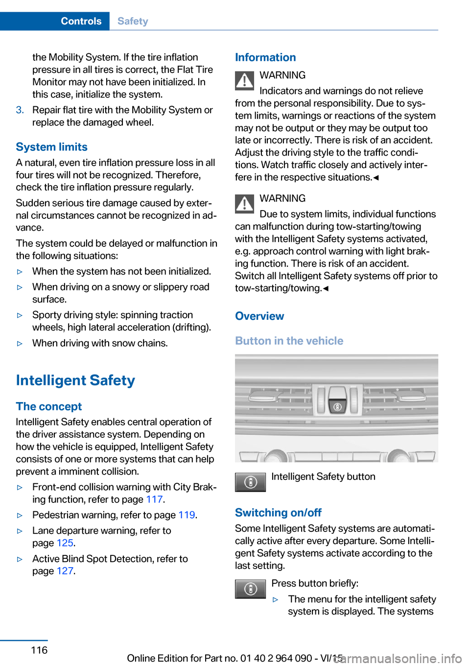
Intelligent Safety button
Switching on/off Some Intelligent Safety systems are automati‐
cally active after every departure. Some Intelli‐
gent Safety systems activate according to the
last setting.
Press button briefly:
▷The menu for the intelligent safety
system is displayed. The systemsSeite 116ControlsSafety116
Online Edition for Part no. 01 40 2 964 090 - VI/15
Page 124 of 255
Switching on/off
Switching on automatically When it is dark outside, the system is automat‐
ically active after every driving-off.
Switching on/off manually Press button briefly:▷The menu for the intelligent safety
system is displayed. The systems
are individually switched off ac‐
cording to their respective set‐
tings.▷LED lights up orange or goes out respec‐
tive to their individual settings.
Adjust as needed. Individual settings are
stored for the profile currently used.
Press button again:
▷All Intelligent Safety systems are
activated.▷The LED lights up green.
Hold down button:
▷All Intelligent Safety systems are
turned off.▷The LED goes out.
Switching on heat image additionally
The heat image from the Night Vision camera
can also be displayed on the Control Display.
This function has no effect on object detec‐
tion.
Press button.
The image from the camera is displayed on the
Control Display.
Adjustments via the iDrive
With heat image switched on:1.Press the controller.2.Select brightness or contrast.▷ Select the symbol.▷ Select the symbol.3.Turn the controller until the desired setting
is selected.4.Press the controller.
Display
Warning of people or animals in
danger
If a collision with a person or an animal de‐
tected in this way is imminent, a warning sym‐
bol appears on the instrument cluster and in
the Head-up Display.
Although both the shape and the heat radiation
are analyzed, false warnings cannot be ruled
out.
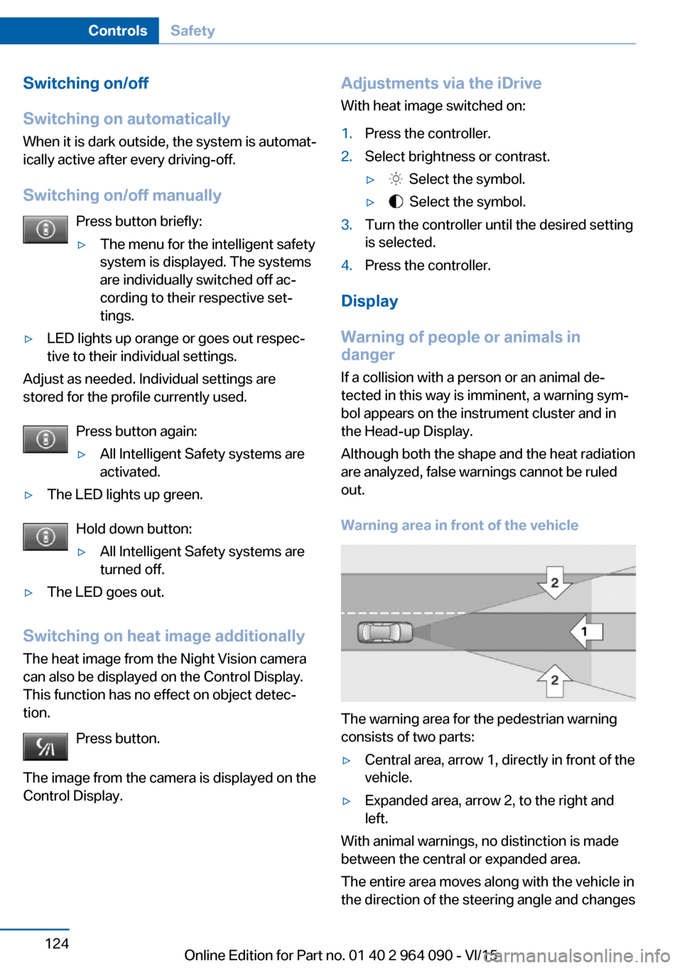
Warning area in front of the vehicle
The warning area for the pedestrian warning
consists of two parts:
▷Central area, arrow 1, directly in front of the
vehicle.▷Expanded area, arrow 2, to the right and
left.
With animal warnings, no distinction is made
between the central or expanded area.
The entire area moves along with the vehicle in
the direction of the steering angle and changes
Seite 124ControlsSafety124
Online Edition for Part no. 01 40 2 964 090 - VI/15
Page 184 of 255
Things to remember when drivingVehicle features and options
This chapter describes all standard, country-
specific and optional features offered with the
series. It also describes features that are not
necessarily available in your car, e. g., due to
the selected options or country versions. This
also applies to safety-related functions and
systems. The respectively applicable country
provisions must be observed when using the
respective features and systems.
Breaking-in period General information
Moving parts need time to adjust to one an‐
other (break-in time).
The following instructions will help accomplish
a long vehicle life and good efficiency.
During break-in, do not use the Launch Con‐
trol, refer to page 84.
Engine, transmission, and axle drive
Up to 1,200 miles/2,000 km
Drive at varying engine and road speeds, but
do not exceed 5,500 rpm and
106 mph/170 km/h.
Avoid full load or kickdown under all circum‐
stances.
At 1,200 miles/2,000 km Have drive-in checkup maintenance per‐
formed.
From 1,200 miles/2,000 km to
3,100 miles/5,000 km
The engine and road speed can gradually be
increased to a constant speed of
137 mph/220 km/h.Use the maximum speed of 155 mph/250 km/h
only briefly, e.g., when passing.
Tires
Tire traction is not optimal due to manufactur‐
ing circumstances when tires are brand-new;
they achieve their full traction potential after a
break-in time.
Drive conservatively for the first
200 miles/300 km.
Brake system
M Compound brakes require an initial break-in
period of approx. 300 miles/500 km to achieve
optimal performance between brake discs and
brake pads. Drive moderately during this
break-in period.
Following part replacement
The same break-in procedures should be ob‐
served if any of the components above-men‐
tioned have to be renewed in the course of the
vehicle's operating life.
General driving notes
Closing the tailgate WARNING
An open tailgate protrudes from the vehi‐
cle and can endanger occupants and other
traffic participants or damage the vehicle in the
event of an accident, braking or evasive ma‐
neuvers. In addition, exhaust fumes may enter
the vehicle interior. There is risk of injuries or
risk of property damage. Do not drive with the
tailgate open.◀
If driving with the tailgate open cannot be
avoided:▷Close all windows and the glass sunroof.Seite 184Driving tipsThings to remember when driving184
Online Edition for Part no. 01 40 2 964 090 - VI/15
Page 185 of 255
▷Greatly increase the air flow from the vents.▷Drive moderately.
Hot exhaust systemWARNING
During driving operation, high tempera‐
tures can occur underneath the body, e.g.
caused by the exhaust gas system. If combus‐
tible materials, such as leaves or grass, come
in contact with hot parts of the exhaust gas
system, these materials can ignite. There is
risk of injuries or risk of property damage.
Do not remove the heat shields installed and
never apply undercoating to them. Make sure
that no combustible materials can come in
contact with hot vehicle parts in driving opera‐
tion, idle or during parking. Do not touch the
hot exhaust system.◀
Mobile communication devices in the
vehicle
WARNING
Vehicle electronics and mobile phones
can influence one another. There is radiation
due to the send operations of mobile phones.
There is risk of injuries or risk of property dam‐
age. If possible, in the car's interior use only
mobile phones with direct connections to an
exterior antenna in order to exclude mutual
disturbance and deflect the radiation from the
car's interior.◀
Hydroplaning
On wet or slushy roads, a wedge of water can
form between the tires and road surface.
This phenomenon is referred to as hydroplan‐
ing. It is characterized by a partial or complete
loss of contact between the tires and the road
surface, ultimately undermining your ability to
steer and brake the vehicle.
Driving through water
CAUTION
When driving too quickly through too
deep water, water can enter into the engine
compartment, the electrical system or the
transmission. There is risk of property damage.
When driving through water, do not exceed the
maximum indicated water level and the maxi‐
mum speed for driving through water.◀
Drive though calm water only and only if it is
not deeper than 17.6 inches/45 cm and at this
height, no faster than walking speed, up to
3 mph/5 km/h.
Braking safely
Your vehicle is equipped with ABS as a stand‐
ard feature.
Applying the brakes fully is the most effective
way of braking in situations needed.
Steering is still responsive. You can still avoid
any obstacles with a minimum of steering ef‐
fort.
The pulsing of the brake pedal indicates that
ABS is in its active mode.
In certain braking situations, the perforated
brake discs can cause functional problems.
However, this has no effect on the perform‐
ance and operational reliability of the brake.
Objects in the movement area around
pedals and floor area
WARNING
Objects in the driver's floor area can limit
the pedal distance or block a depressed pedal.
There is risk of an accident. Stow objects in
the vehicle such that they are secured and
cannot enter into the driver's floor area. Use
floor mats that are suitable for the vehicle and
can be safely attached to the floor. Do not use
loose floor mats and do not layer several floor
mats. Make sure that there is sufficient clear‐
ance for the pedals. Ensure that the floor matsSeite 185Things to remember when drivingDriving tips185
Online Edition for Part no. 01 40 2 964 090 - VI/15
Page 187 of 255

▷Adjust the speed to the road surface con‐
ditions. The steeper and more uneven the
road surface, the slower the speed should
be.▷When driving on steep uphill or downhill
grades: add engine oil and coolant up to
near the MAX mark. Uphill and downhill
grades can be traveled up to no more than
50 %.▷On steep downhill grades, use Hill Descent
Control HDC, refer to page 136.
Starting out is possible on uphill grades up
to 32 %. The permissible side tilt is 50 %.▷Avoid that the chassis bottom coming in
contact with the ground.
The ground clearance is no more than 7.8
inches/20 cm and can vary according to
the vehicle's load.▷When wheels continue to spin, depress the
accelerator so that driving stability control
systems can distribute the driving force to
the wheels. Activate DTC Dynamic Trac‐
tion Control if available.
After a trip on poor roads
After a trip on poor roads, check wheels and
tires for damage to maintain driving safety.
Clear heavy soiling from the body.
Seite 187Things to remember when drivingDriving tips187
Online Edition for Part no. 01 40 2 964 090 - VI/15
Page 188 of 255
LoadingVehicle features and options
This chapter describes all standard, country-
specific and optional features offered with the
series. It also describes features that are not
necessarily available in your car, e. g., due to
the selected options or country versions. This
also applies to safety-related functions and
systems. The respectively applicable country
provisions must be observed when using the
respective features and systems.
Information WARNING
High gross weight can overheat the tires,
damage them internally, and cause a sudden
drop in tire inflation pressure. There is risk of
an accident. Pay attention to the permitted
load capacity of the tires and never exceed the
permitted gross weight.◀
CAUTION
Fluids in the cargo area can cause dam‐
age. There is risk of property damage. Make
sure that no fluids leak in the cargo area.◀
WARNING
Loose objects in the car's interior can be
thrown into the car's interior while driving, e.g.
in the event of an accident or during braking
and evasive maneuvers. There is risk of inju‐
ries. Secure loose objects in the car's inte‐
rior.◀
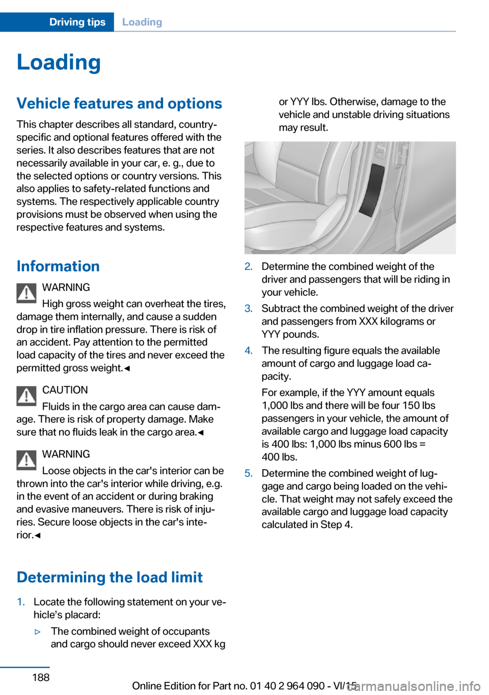
Determining the load limit1.Locate the following statement on your ve‐
hicle’s placard:▷The combined weight of occupants
and cargo should never exceed XXX kgor YYY lbs. Otherwise, damage to the
vehicle and unstable driving situations
may result.2.Determine the combined weight of the
driver and passengers that will be riding in
your vehicle.3.Subtract the combined weight of the driver
and passengers from XXX kilograms or
YYY pounds.4.The resulting figure equals the available
amount of cargo and luggage load ca‐
pacity.
For example, if the YYY amount equals
1,000 lbs and there will be four 150 lbs
passengers in your vehicle, the amount of
available cargo and luggage load capacity
is 400 lbs: 1,000 lbs minus 600 lbs =
400 lbs.5.Determine the combined weight of lug‐
gage and cargo being loaded on the vehi‐
cle. That weight may not safely exceed the
available cargo and luggage load capacity
calculated in Step 4.Seite 188Driving tipsLoading188
Online Edition for Part no. 01 40 2 964 090 - VI/15