2015 BMW X4 Rear brake light malfunction
[x] Cancel search: Rear brake light malfunctionPage 113 of 253

Adjust as needed. Individual settings are
stored for the profile currently used.
Press button again:▷All Intelligent Safety systems are
activated.▷The LED lights up green.
Hold down button:
▷All Intelligent Safety systems are
turned off.▷The LED goes out.
Front-end collision warning
Depending on the equipment, the collision
warning system consists of one of the two sys‐
tems:
▷Front-end collision warning with City Brak‐
ing function, refer to page 113.▷Front-end collision warning with braking
function, refer to page 116
Front-end collision warning
with City Braking function
The concept The system can help prevent accidents. If an
accident cannot be prevented, the system will
help reduce the collision speed.
The system sounds a warning before an immi‐
nent collision and actuates brakes independ‐
ently if needed.
The automatic braking intervention is done
with limited force and duration.
A camera in the area of the rearview mirror
controls the system.
The front-end collision warning is available
even if cruise control has been deactivated.
With the vehicle approaching another vehicle
intentionally, the collision warning and braking
are delayed in order to avoid false system re‐
actions.
General information
The system warns at two levels of an imminent
danger of collision at speeds from approx.
3 mph/5 km/h. Time of warnings may vary with
the current driving situation.
Appropriate braking kicks in at speeds of up to
35 mph/60 km/h.
Detection range
It responds to objects if they are detected by
the system.
Information WARNING
Indicators and warnings do not relieve
from the personal responsibility. Due to sys‐
tem limits, warnings or reactions of the system
may not be output or they may be output too
late or incorrectly. There is risk of an accident.
Adjust the driving style to the traffic condi‐
tions. Watch traffic closely and actively inter‐
fere in the respective situations.◀
WARNING
Due to system limits, individual functions
can malfunction during tow-starting/towing
with the Intelligent Safety systems activated,
e.g. approach control warning with light brak‐
ing function. There is risk of an accident.
Switch all Intelligent Safety systems off prior to
tow-starting/towing.◀
Seite 113SafetyControls113
Online Edition for Part no. 01 40 2 964 144 - VI/15
Page 221 of 253

4.Detach the connector.5.Turn the bulb bracket and remove it.6.Remove the bulb and replace it.7.Proceed in reverse order to insert the front
fog lamp. Note the guide rails in doing so.
LED front fog lights
These front fog lights are made using LED
technology. Contact a dealer’s service center
or another qualified service center or repair
shop in the event of a malfunction.
Turn signal
Information
Follow general instructions, refer to page 217.
The turn signals are located next to each low
beam in the engine compartment.
21-watt bulb, PY 21W.
Replacement1.Open the hood, refer to page 207.2.Turn the bulb with the socket counter‐
clockwise and carefully remove.3.Push the bulb down slightly and unscrew
from the socket.4.To insert the new bulb, proceed in reverse
order of removal.
Turn signal in exterior mirror
The turn signals in the exterior mirrors feature
LED technology. Contact a dealer’s service
center or another qualified service center or re‐
pair shop in the event of a malfunction.
Tail lights, bulb replacement
Overview
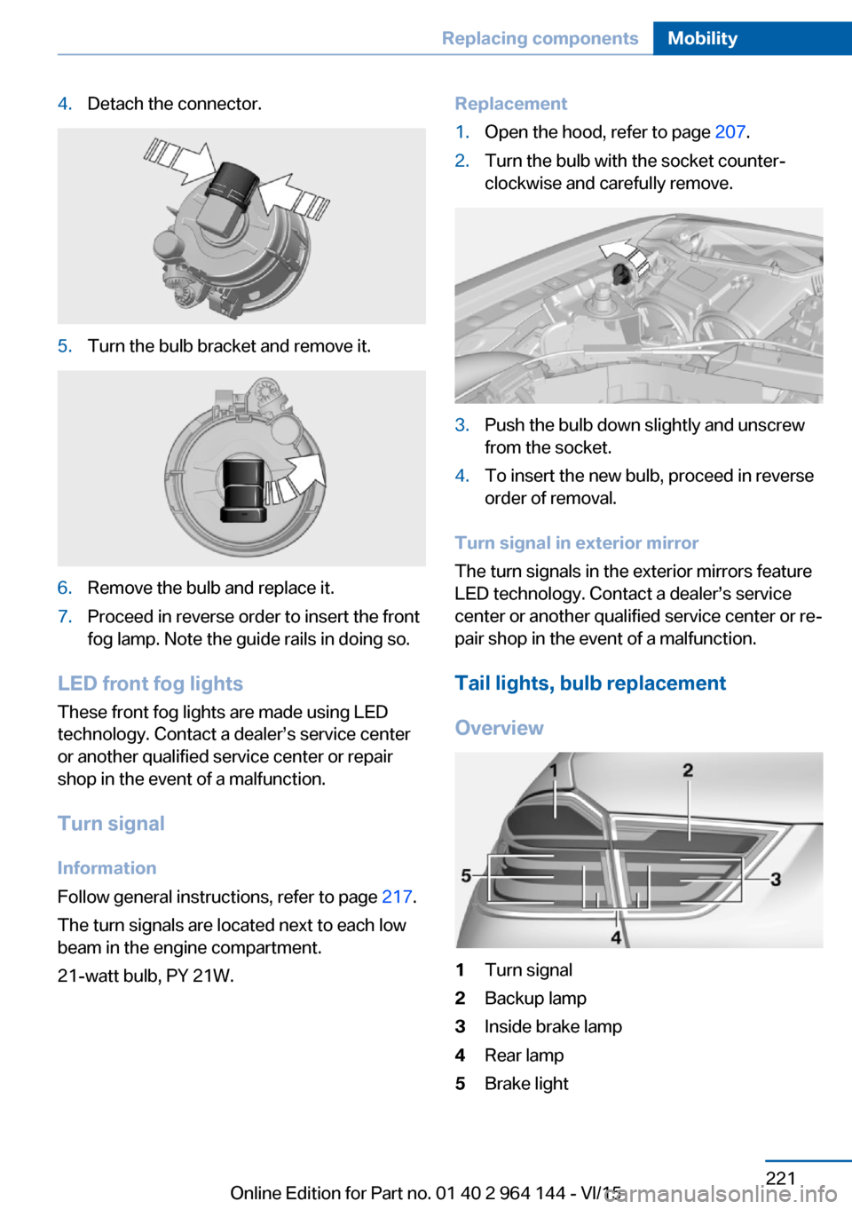
1Turn signal2Backup lamp3Inside brake lamp4Rear lamp5Brake lightSeite 221Replacing componentsMobility221
Online Edition for Part no. 01 40 2 964 144 - VI/15
Page 222 of 253

Bulb replacement, exterior tail lightsGeneral information
Follow general instructions, refer to page 217.
Turn signal: 21-watt bulb, P21W.
Outer brake lamp: 24-watt bulb, PW24W.
The rear lamp features LED technology. Con‐
tact a dealer’s service center or another quali‐
fied service center or repair shop in the event
of a malfunction.
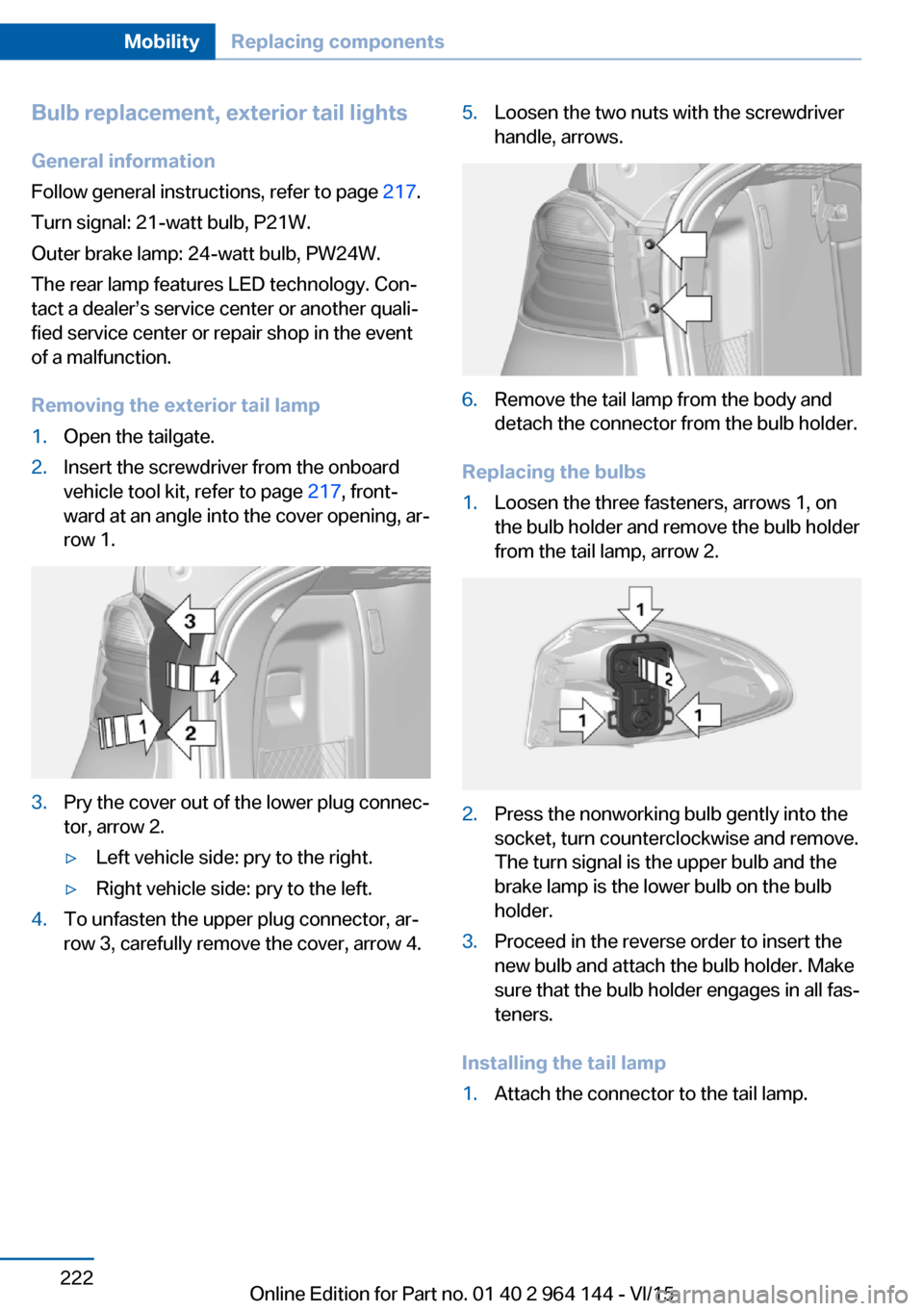
Removing the exterior tail lamp1.Open the tailgate.2.Insert the screwdriver from the onboard
vehicle tool kit, refer to page 217, front‐
ward at an angle into the cover opening, ar‐
row 1.3.Pry the cover out of the lower plug connec‐
tor, arrow 2.▷Left vehicle side: pry to the right.▷Right vehicle side: pry to the left.4.To unfasten the upper plug connector, ar‐
row 3, carefully remove the cover, arrow 4.5.Loosen the two nuts with the screwdriver
handle, arrows.6.Remove the tail lamp from the body and
detach the connector from the bulb holder.
Replacing the bulbs
1.Loosen the three fasteners, arrows 1, on
the bulb holder and remove the bulb holder
from the tail lamp, arrow 2.2.Press the nonworking bulb gently into the
socket, turn counterclockwise and remove.
The turn signal is the upper bulb and the
brake lamp is the lower bulb on the bulb
holder.3.Proceed in the reverse order to insert the
new bulb and attach the bulb holder. Make
sure that the bulb holder engages in all fas‐
teners.
Installing the tail lamp
1.Attach the connector to the tail lamp.Seite 222MobilityReplacing components222
Online Edition for Part no. 01 40 2 964 144 - VI/15
Page 223 of 253

2.Place the cover on the three fixing points,
arrows, and push in. Make sure that the tail
lamp engages in the fasteners.3.Screw the two nuts tight and mount the
cover.
Lights in the tailgate
General information
Follow general instructions, refer to page 217.
Reversing lights: 21-watt bulb, P21W
Inner brake lamp: 21-watt bulb, H21W.
Accessing the lights
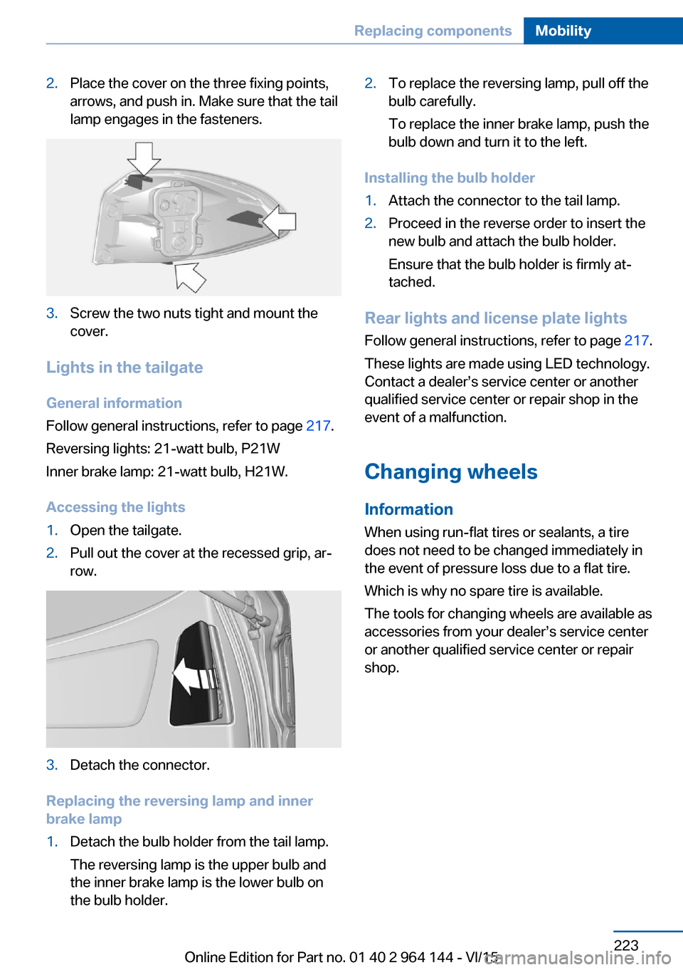
1.Open the tailgate.2.Pull out the cover at the recessed grip, ar‐
row.3.Detach the connector.
Replacing the reversing lamp and inner
brake lamp
1.Detach the bulb holder from the tail lamp.
The reversing lamp is the upper bulb and
the inner brake lamp is the lower bulb on
the bulb holder.2.To replace the reversing lamp, pull off the
bulb carefully.
To replace the inner brake lamp, push the
bulb down and turn it to the left.
Installing the bulb holder
1.Attach the connector to the tail lamp.2.Proceed in the reverse order to insert the
new bulb and attach the bulb holder.
Ensure that the bulb holder is firmly at‐
tached.
Rear lights and license plate lights
Follow general instructions, refer to page 217.
These lights are made using LED technology.
Contact a dealer’s service center or another
qualified service center or repair shop in the
event of a malfunction.
Changing wheels
Information When using run-flat tires or sealants, a tire
does not need to be changed immediately in
the event of pressure loss due to a flat tire.
Which is why no spare tire is available.
The tools for changing wheels are available as
accessories from your dealer’s service center
or another qualified service center or repair
shop.
Seite 223Replacing componentsMobility223
Online Edition for Part no. 01 40 2 964 144 - VI/15
Page 247 of 253

Luggage rack, refer to Roof-mounted luggage rack 182
Lumbar support 54
M
Maintenance 215
Maintenance require‐ ments 215
Maintenance, service require‐ ments 89
Maintenance system, BMW 215
Make-up mirror 165
Malfunction displays, see Check Control 83
Manual air distribu‐ tion 157, 160
Manual air flow 157, 160
Manual brake, see Parking brake 71
Manual mode, Steptronic transmission 78
Manual operation, door lock 39
Manual operation, exterior mirrors 60
Manual operation, fuel filler flap 192
Manual operation, Park Dis‐ tance Control PDC 143
Manual operation, rearview camera 145
Manual operation, Top View 148
Marking, run-flat tires 202
Master key, see Remote con‐ trol 34
Maximum cooling 159
Maximum speed, display 90
Maximum speed, winter tires 202
Measurement, units of 95
Medical kit 227
Memory, seat, mirror 58
Menu, EfficientDynamics 186 Menu in instrument clus‐
ter 91
Menus, operating, iDrive 18
Menus, refer to iDrive operat‐ ing concept 20
Messages, see Check Con‐ trol 83
Microfilter 157, 160
Minimum tread, tires 200
Mirror 59
Mirror memory 58
Mobile communication devi‐ ces in the vehicle 177
Mobility System 203
Modifications, technical, see Own Safety 7
Moisture in headlight 218
Monitor, see Control Dis‐ play 18
Mounting of child restraint systems 64
Moving sun visor 165
Multifunction steering wheel, buttons 14
N
Navigation, see user's manual for Navigation, Entertain‐
ment and Communication
Neck restraints, front, see Head restraints 57
Neck restraints, rear, see Head restraints 58
Neutral cleaner, see wheel cleaner 233
New wheels and tires 201
Nylon rope for tow-starting/ towing 229
O OBD Onboard Diagnosis 216
OBD, see OBD Onboard Di‐ agnosis 216 Obstacle marking, rearview
camera 146
Octane rating, see Recom‐ mended fuel grade 194
Odometer 87
Office, see user's manual for Navigation, Entertainment
and Communication
Offroad trips 176
Oil 209
Oil, adding 210
Oil additives 211
Oil change 211
Oil change interval, service requirements 89
Oil filler neck 210
Oil types, alternative 211
Oil types, suitable 211
Old batteries, disposal 225
On-board computer 92
On-board computer, refer to On-board computer 92
Onboard monitor, see Control Display 18
Onboard vehicle tool kit 217
Opening/closing via door lock 39
Opening and closing 34
Opening and closing, without remote control 39
Opening and closing, with re‐ mote control 37
Opening the tailgate with no- touch activation 44
Operating concept, iDrive 18
Optional equipment, standard equipment 7
Outside air, refer to Auto‐ matic recirculated-air con‐
trol 159
Overheating of engine, see Coolant temperature 87
Own Safety 7 Seite 247Everything from A to ZReference247
Online Edition for Part no. 01 40 2 964 144 - VI/15