2015 BMW X4 brake
[x] Cancel search: brakePage 177 of 253
grades can be traveled up to no more than
50 %.▷On steep downhill grades, use Hill Descent
Control HDC, refer to page 128.
Starting out is possible on uphill grades up
to 30 %. The permissible side tilt is 30 %.▷Avoid that the chassis bottom coming in
contact with the ground.
The ground clearance is no more than 7.8
inches/20 cm and can vary according to
the vehicle's load.▷When wheels continue to spin, depress the
accelerator so that driving stability control
systems can distribute the driving force to
the wheels. Activate DTC Dynamic Trac‐
tion Control if available.
After a trip on poor roads
After a trip on poor roads, check wheels and
tires for damage to maintain driving safety.
Clear heavy soiling from the body.
General driving notes
Closing the tailgate WARNING
An open tailgate protrudes from the vehi‐
cle and can endanger occupants and other
traffic participants or damage the vehicle in the
event of an accident, braking or evasive ma‐
neuvers. In addition, exhaust fumes may enter
the vehicle interior. There is risk of injuries or
risk of property damage. Do not drive with the
tailgate open.◀
If driving with the tailgate open cannot be
avoided:
▷Close all windows and the glass sunroof.▷Greatly increase the air flow from the vents.▷Drive moderately.Hot exhaust system
WARNING
During driving operation, high tempera‐
tures can occur underneath the body, e.g.
caused by the exhaust gas system. If combus‐
tible materials, such as leaves or grass, come
in contact with hot parts of the exhaust gas
system, these materials can ignite. There is
risk of injuries or risk of property damage.
Do not remove the heat shields installed and
never apply undercoating to them. Make sure
that no combustible materials can come in
contact with hot vehicle parts in driving opera‐
tion, idle or during parking. Do not touch the
hot exhaust system.◀
Mobile communication devices in the
vehicle
WARNING
Vehicle electronics and mobile phones
can influence one another. There is radiation
due to the send operations of mobile phones.
There is risk of injuries or risk of property dam‐
age. If possible, in the car's interior use only
mobile phones with direct connections to an
exterior antenna in order to exclude mutual
disturbance and deflect the radiation from the
car's interior.◀
Hydroplaning
On wet or slushy roads, a wedge of water can
form between the tires and road surface.
This phenomenon is referred to as hydroplan‐
ing. It is characterized by a partial or complete
loss of contact between the tires and the road
surface, ultimately undermining your ability to
steer and brake the vehicle.
Driving through water CAUTION
When driving too quickly through too
deep water, water can enter into the engine
compartment, the electrical system or theSeite 177Things to remember when drivingDriving tips177
Online Edition for Part no. 01 40 2 964 144 - VI/15
Page 178 of 253
transmission. There is risk of property damage.
When driving through water, do not exceed the
maximum indicated water level and the maxi‐
mum speed for driving through water.◀
Drive though calm water only and only if it is
not deeper than 19.6 inches/50 cm and at this
height, no faster than walking speed, up to
3 mph/5 km/h.
Braking safely Your vehicle is equipped with ABS as a stand‐
ard feature.
Applying the brakes fully is the most effective
way of braking in situations needed.
Steering is still responsive. You can still avoid
any obstacles with a minimum of steering ef‐
fort.
Pulsation of the brake pedal and sounds from
the hydraulic circuits indicate that ABS is in its
active mode.
In certain braking situations, the perforated
brake discs can cause functional problems.
However, this has no effect on the perform‐
ance and operational reliability of the brake.
Objects in the movement area around
pedals and floor area
WARNING
Objects in the driver's floor area can limit
the pedal distance or block a depressed pedal.
There is risk of an accident. Stow objects in
the vehicle such that they are secured and
cannot enter into the driver's floor area. Use
floor mats that are suitable for the vehicle and
can be safely attached to the floor. Do not use
loose floor mats and do not layer several floor
mats. Make sure that there is sufficient clear‐
ance for the pedals. Ensure that the floor mats
are securely fastened again after they were re‐
moved, e.g. for cleaning.◀Driving in wet conditions
When roads are wet, salted, or in heavy rain,
press brake pedal ever so gently every few
miles.
Ensure that this action does not endanger
other traffic.
The heat generated in this process helps dry
the brake discs and pads.
In this way braking efficiency will be available
when you need it.
Hills WARNING
Light but consistent brake pressure can
lead to high temperatures, brakes wearing out
and possibly even brake failure. There is risk of
an accident. Avoid placing excessive stress on
the brake system.◀
WARNING
In idle or with the engine switched off,
safety-relevant functions are restricted or not
available anymore, e.g. braking effect of the
engine or braking force and steering support.
There is risk of an accident. Do not drive in idle
or with the engine switched off.◀
Drive long or steep downhill gradients in the
gear that requires least braking efforts. Other‐
wise the brakes may overheat and reduce
brake efficiency.
You can increase the engine's braking effect
by shifting down, going all the way to first gear,
if needed.
Brake disc corrosion
Corrosion on the brake discs and contamina‐
tion on the brake pads are furthered by the fol‐
lowing circumstances:▷Low mileage.▷Extended periods when the vehicle is not
used at all.▷Infrequent use of the brakes.Seite 178Driving tipsThings to remember when driving178
Online Edition for Part no. 01 40 2 964 144 - VI/15
Page 179 of 253
Corrosion will built up when the maximum
pressure applied to the brake pads during
braking is not reached - thus discs don't get
cleaned.
Corrosion buildup on the brake discs will cause
a pulsating effect on the brakes in their re‐
sponse - generally that cannot be corrected.
Condensation under the parked
vehicle
When using the automatic climate control,
condensation water develops collecting under‐
neath the vehicle.
These traces of water under the vehicle are
normal.Seite 179Things to remember when drivingDriving tips179
Online Edition for Part no. 01 40 2 964 144 - VI/15
Page 187 of 253
Vertical bars show consumption for the se‐
lected time frame.
Trip interruptions are represented below the
bar on the time axis.
"Consumption history"
Adjusting fuel consumption history time frame
Select the symbol.
Resetting fuel consumption history
1.Open "Options".2."Reset consumption history"
Displaying EfficientDynamics info
The current efficiency can be displayed.
"EfficientDynamics info"
The following systems are displayed:
▷Auto Start/Stop function.▷Energy recovery.▷Climate control output.▷Coasting.
Display ECO PRO tips
"ECO PRO tips"
Settings are stored for the profile currently
used.
Coasting
The concept The system helps to conserve fuel.
To do this, under certain conditions the engine
is automatically decoupled from the transmis‐
sion when selector lever position D is set. The
vehicle continues traveling with the engine
idling to reduce fuel consumption. Selector
lever position D remains engaged.
This driving condition is referred to as coast‐
ing.
As soon as you step on the brake or accelera‐
tor pedal, the engine is automatically coupled
again.
Information Coasting is a component of the ECO PRO, re‐
fer to page 184, driving mode.
Coasting is automatically activated when ECO
PRO mode is called via the Driving Dynamics
Control.
The function is available in a certain speed
range.
A proactively driving style helps the driver to
use the function as often as possible and sup‐
ports the fuel-conserving effect of coasting.
Safety mode
The function is not available under one of the
following conditions.▷DSC OFF or TRACTION activated.▷Driving in the dynamic limit range and on
steep uphill or downhill grades.▷Battery charge status temporarily too low
or vehicle electrical system drawing exces‐
sive current.▷Cruise control activated.
Functional requirements
In ECO PRO mode, this function is available in
a speed range from approximately 30 mph, ap‐
prox. 50 km/h to 100 mph, approx. 160 km/h, if
the following conditions are met:
▷Accelerator pedal and brake pedal are not
operated.▷The selector lever is in selector lever posi‐
tion D.▷Engine and transmission are at operating
temperature.
The driving status Coast can be influenced
with the shift paddles.
Seite 187Saving fuelDriving tips187
Online Edition for Part no. 01 40 2 964 144 - VI/15
Page 215 of 253
MaintenanceVehicle features and options
This chapter describes all standard, country-
specific and optional features offered with the
series. It also describes features that are not
necessarily available in your car, e. g., due to
the selected options or country versions. This
also applies to safety-related functions and
systems. The respectively applicable country
provisions must be observed when using the
respective features and systems.
BMW maintenance system The maintenance system indicates required
maintenance measures, and thereby provides
support in maintaining road safety and the op‐
erational reliability of the vehicle.
In some cases scopes and intervals may vary
according to the country-specific version. Re‐
placement work, spare parts, fuels and lubri‐
cants and wear materials are calculated sepa‐
rately. Further information is available from a
dealer’s service center or another qualified
service center or repair shop.
Condition Based ServiceCBS
Sensors and special algorithms take into ac‐
count the driving conditions of your vehicle.
Based on this, Condition Based Service recog‐
nizes the maintenance requirements.
The system makes it possible to adapt the
amount of maintenance corresponding to your
user profile.
Detailed information on service requirements,
refer to page 89, can be displayed on the Con‐
trol Display.Service data in the remote control
Information on the required maintenance is
continuously stored in the remote control. The dealer’s service center can read this data out
and suggest an optimized maintenance scope
for your vehicle.
Therefore, hand the service advisor the remote
control with which the vehicle was driven most
recently.
Storage periods Storage periods during which the vehicle bat‐
tery was disconnected are not taken into ac‐
count.
If this occurs, have a dealer's service center or
another qualified service center or repair shop
update the time-dependent maintenance pro‐
cedures, such as checking brake fluid and, if
necessary, changing the engine oil and the mi‐
crofilter/activated-charcoal filter.
Service and WarrantyInformation Booklet for US
models and Warranty and
Service Guide Booklet for
Canadian models
Please consult your Service and Warranty In‐
formation Booklet for US models and Warranty
and Service Guide Booklet for Canadian mod‐
els for additional information on service re‐
quirements.
The manufacturer of your vehicle recommends
that maintenance and repair be performed by a
dealer’s service center or another qualified
service center or repair shop. Records of regu‐
lar maintenance and repair work should be re‐
tained.Seite 215MaintenanceMobility215
Online Edition for Part no. 01 40 2 964 144 - VI/15
Page 221 of 253
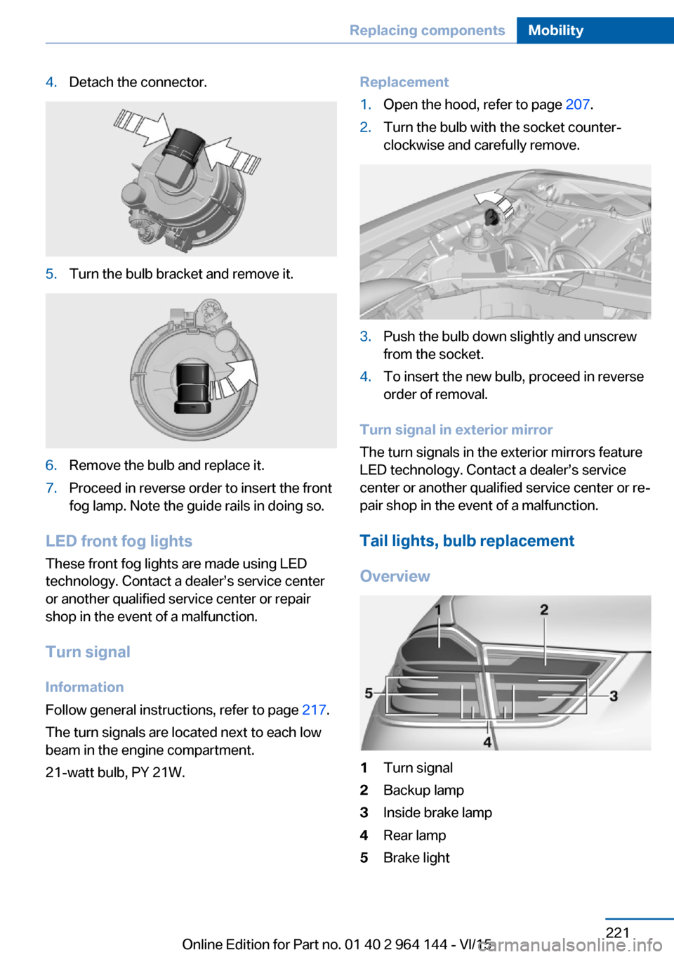
4.Detach the connector.5.Turn the bulb bracket and remove it.6.Remove the bulb and replace it.7.Proceed in reverse order to insert the front
fog lamp. Note the guide rails in doing so.
LED front fog lights
These front fog lights are made using LED
technology. Contact a dealer’s service center
or another qualified service center or repair
shop in the event of a malfunction.
Turn signal
Information
Follow general instructions, refer to page 217.
The turn signals are located next to each low
beam in the engine compartment.
21-watt bulb, PY 21W.
Replacement1.Open the hood, refer to page 207.2.Turn the bulb with the socket counter‐
clockwise and carefully remove.3.Push the bulb down slightly and unscrew
from the socket.4.To insert the new bulb, proceed in reverse
order of removal.
Turn signal in exterior mirror
The turn signals in the exterior mirrors feature
LED technology. Contact a dealer’s service
center or another qualified service center or re‐
pair shop in the event of a malfunction.
Tail lights, bulb replacement
Overview
1Turn signal2Backup lamp3Inside brake lamp4Rear lamp5Brake lightSeite 221Replacing componentsMobility221
Online Edition for Part no. 01 40 2 964 144 - VI/15
Page 222 of 253
Bulb replacement, exterior tail lightsGeneral information
Follow general instructions, refer to page 217.
Turn signal: 21-watt bulb, P21W.
Outer brake lamp: 24-watt bulb, PW24W.
The rear lamp features LED technology. Con‐
tact a dealer’s service center or another quali‐
fied service center or repair shop in the event
of a malfunction.
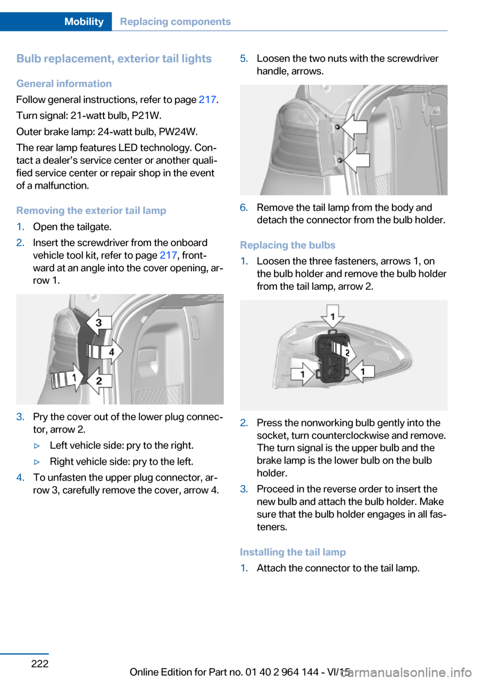
Removing the exterior tail lamp1.Open the tailgate.2.Insert the screwdriver from the onboard
vehicle tool kit, refer to page 217, front‐
ward at an angle into the cover opening, ar‐
row 1.3.Pry the cover out of the lower plug connec‐
tor, arrow 2.▷Left vehicle side: pry to the right.▷Right vehicle side: pry to the left.4.To unfasten the upper plug connector, ar‐
row 3, carefully remove the cover, arrow 4.5.Loosen the two nuts with the screwdriver
handle, arrows.6.Remove the tail lamp from the body and
detach the connector from the bulb holder.
Replacing the bulbs
1.Loosen the three fasteners, arrows 1, on
the bulb holder and remove the bulb holder
from the tail lamp, arrow 2.2.Press the nonworking bulb gently into the
socket, turn counterclockwise and remove.
The turn signal is the upper bulb and the
brake lamp is the lower bulb on the bulb
holder.3.Proceed in the reverse order to insert the
new bulb and attach the bulb holder. Make
sure that the bulb holder engages in all fas‐
teners.
Installing the tail lamp
1.Attach the connector to the tail lamp.Seite 222MobilityReplacing components222
Online Edition for Part no. 01 40 2 964 144 - VI/15
Page 223 of 253
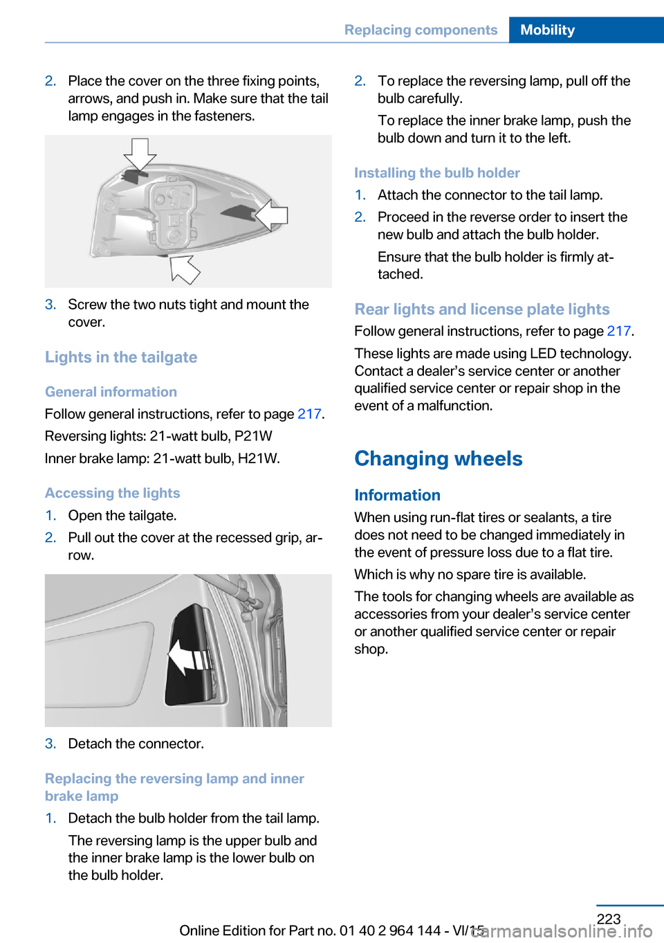
2.Place the cover on the three fixing points,
arrows, and push in. Make sure that the tail
lamp engages in the fasteners.3.Screw the two nuts tight and mount the
cover.
Lights in the tailgate
General information
Follow general instructions, refer to page 217.
Reversing lights: 21-watt bulb, P21W
Inner brake lamp: 21-watt bulb, H21W.
Accessing the lights
1.Open the tailgate.2.Pull out the cover at the recessed grip, ar‐
row.3.Detach the connector.
Replacing the reversing lamp and inner
brake lamp
1.Detach the bulb holder from the tail lamp.
The reversing lamp is the upper bulb and
the inner brake lamp is the lower bulb on
the bulb holder.2.To replace the reversing lamp, pull off the
bulb carefully.
To replace the inner brake lamp, push the
bulb down and turn it to the left.
Installing the bulb holder
1.Attach the connector to the tail lamp.2.Proceed in the reverse order to insert the
new bulb and attach the bulb holder.
Ensure that the bulb holder is firmly at‐
tached.
Rear lights and license plate lights
Follow general instructions, refer to page 217.
These lights are made using LED technology.
Contact a dealer’s service center or another
qualified service center or repair shop in the
event of a malfunction.
Changing wheels
Information When using run-flat tires or sealants, a tire
does not need to be changed immediately in
the event of pressure loss due to a flat tire.
Which is why no spare tire is available.
The tools for changing wheels are available as
accessories from your dealer’s service center
or another qualified service center or repair
shop.
Seite 223Replacing componentsMobility223
Online Edition for Part no. 01 40 2 964 144 - VI/15