2015 BMW X4 check engine
[x] Cancel search: check enginePage 213 of 253
CoolantVehicle features and optionsThis chapter describes all standard, country-
specific and optional features offered with the
series. It also describes features that are not
necessarily available in your car, e. g., due to
the selected options or country versions. This
also applies to safety-related functions and
systems. The respectively applicable country
provisions must be observed when using the
respective features and systems.
Information WARNING
With the engine hot and the cooling sys‐
tem open, coolant can escape and lead to
burns. There is risk of injuries. Only open the
cooling system with the engine cooled down.◀
WARNING
Additives are harmful and incorrect addi‐
tives can damage the engine. There is risk of
injuries and risk of property damage. Avoid the
contact of articles of clothing, skin or eyes with
additives. Do not swallow any additives. Use
suitable additives only.◀
Coolant consists of water and additives.
Not all commercially available additives are
suitable for the vehicle. Information about suit‐
able additives is available from a dealer’s serv‐
ice center or another qualified service center or
repair shop.
Coolant level
Overview
Depending on the engine installation, the cool‐
ant reservoir is located on the right side or the
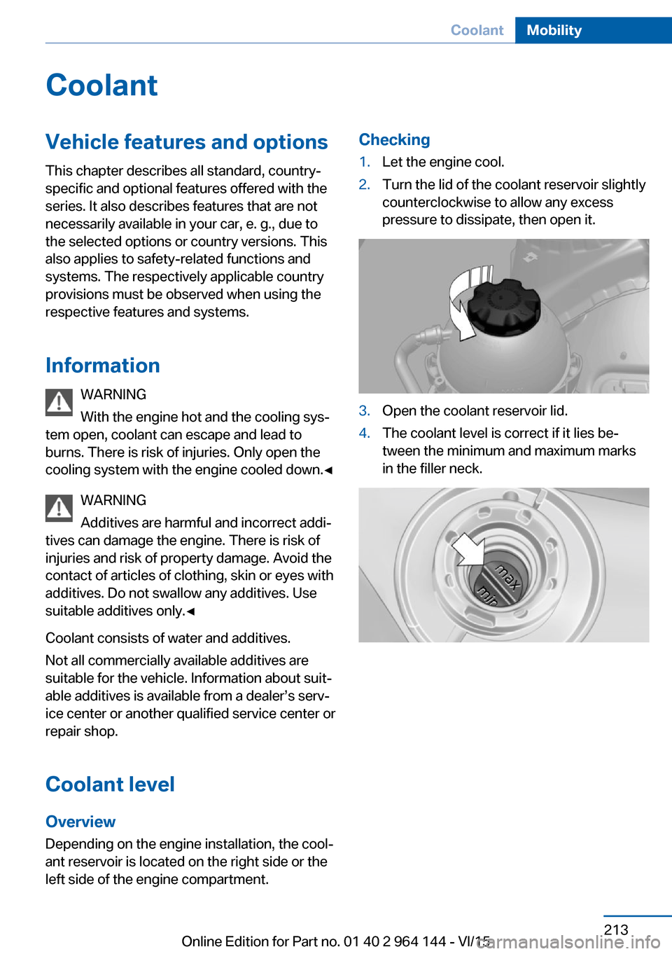
left side of the engine compartment.Checking1.Let the engine cool.2.Turn the lid of the coolant reservoir slightly
counterclockwise to allow any excess
pressure to dissipate, then open it.3.Open the coolant reservoir lid.4.The coolant level is correct if it lies be‐
tween the minimum and maximum marks
in the filler neck.Seite 213CoolantMobility213
Online Edition for Part no. 01 40 2 964 144 - VI/15
Page 215 of 253
MaintenanceVehicle features and options
This chapter describes all standard, country-
specific and optional features offered with the
series. It also describes features that are not
necessarily available in your car, e. g., due to
the selected options or country versions. This
also applies to safety-related functions and
systems. The respectively applicable country
provisions must be observed when using the
respective features and systems.
BMW maintenance system The maintenance system indicates required
maintenance measures, and thereby provides
support in maintaining road safety and the op‐
erational reliability of the vehicle.
In some cases scopes and intervals may vary
according to the country-specific version. Re‐
placement work, spare parts, fuels and lubri‐
cants and wear materials are calculated sepa‐
rately. Further information is available from a
dealer’s service center or another qualified
service center or repair shop.
Condition Based ServiceCBS
Sensors and special algorithms take into ac‐
count the driving conditions of your vehicle.
Based on this, Condition Based Service recog‐
nizes the maintenance requirements.
The system makes it possible to adapt the
amount of maintenance corresponding to your
user profile.
Detailed information on service requirements,
refer to page 89, can be displayed on the Con‐
trol Display.Service data in the remote control
Information on the required maintenance is
continuously stored in the remote control. The dealer’s service center can read this data out
and suggest an optimized maintenance scope
for your vehicle.
Therefore, hand the service advisor the remote
control with which the vehicle was driven most
recently.
Storage periods Storage periods during which the vehicle bat‐
tery was disconnected are not taken into ac‐
count.
If this occurs, have a dealer's service center or
another qualified service center or repair shop
update the time-dependent maintenance pro‐
cedures, such as checking brake fluid and, if
necessary, changing the engine oil and the mi‐
crofilter/activated-charcoal filter.
Service and WarrantyInformation Booklet for US
models and Warranty and
Service Guide Booklet for
Canadian models
Please consult your Service and Warranty In‐
formation Booklet for US models and Warranty
and Service Guide Booklet for Canadian mod‐
els for additional information on service re‐
quirements.
The manufacturer of your vehicle recommends
that maintenance and repair be performed by a
dealer’s service center or another qualified
service center or repair shop. Records of regu‐
lar maintenance and repair work should be re‐
tained.Seite 215MaintenanceMobility215
Online Edition for Part no. 01 40 2 964 144 - VI/15
Page 216 of 253

Socket for OBD Onboard
Diagnosis
Information CAUTION
Improper use of the socket for Onboard
Diagnosis can lead to vehicle malfunctions.
There is risk of property damage. The manu‐
facturer of your vehicle strongly recommends
access to the socket for Onboard Diagnosis be
limited to a dealer's service center, another
qualified service center or repair shop or other
authorized persons.◀
Position
There is an OBD socket on the driver's side for
checking the primary components in the vehi‐
cle's emissions.
Emissions
▷The warning lamp lights up:
Emissions are deteriorating. Have
the vehicle checked as soon as
possible.▷The warning lamp flashes under certain
circumstances:
This indicates that there is excessive mis‐
firing in the engine.
Reduce the vehicle speed and have the
system checked immediately; otherwise,
serious engine misfiring within a brief pe‐
riod can seriously damage emission con‐trol components, in particular the catalytic
converter.Seite 216MobilityMaintenance216
Online Edition for Part no. 01 40 2 964 144 - VI/15
Page 224 of 253
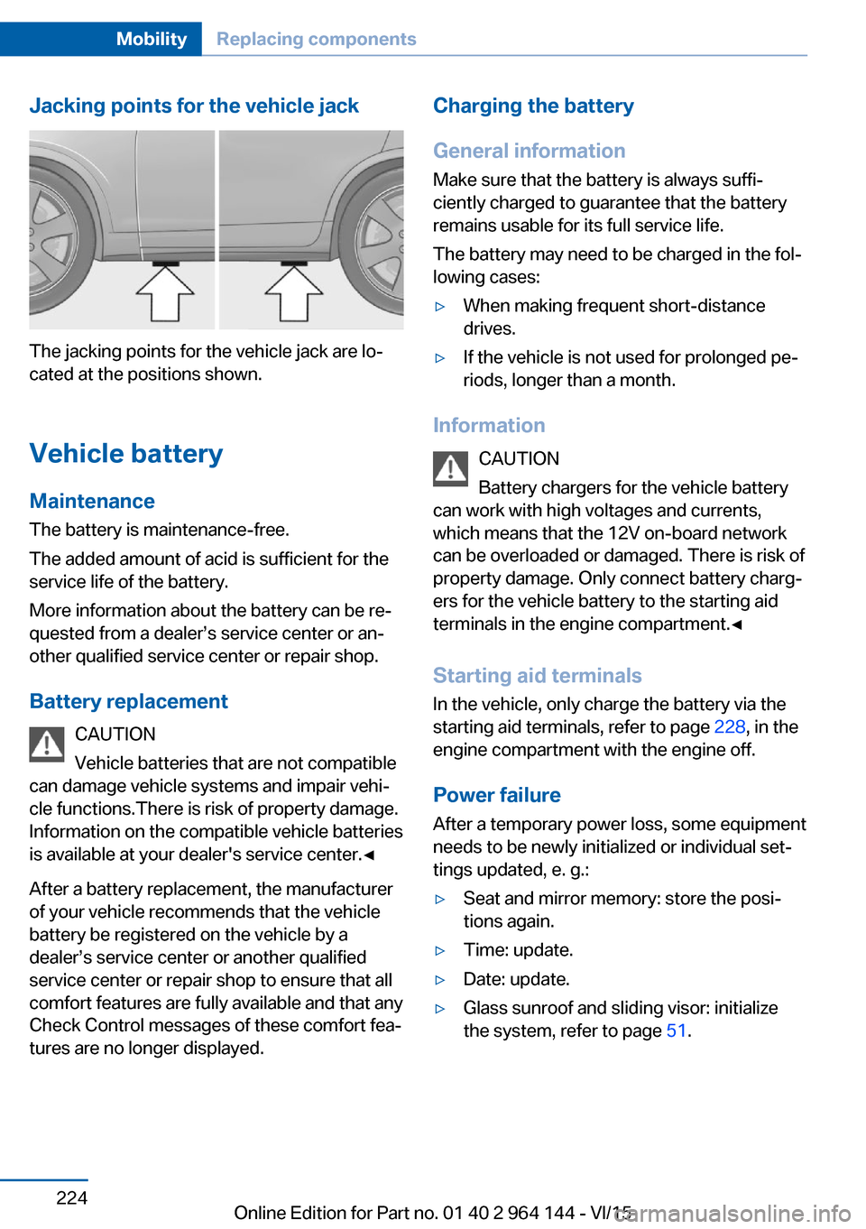
Jacking points for the vehicle jack
The jacking points for the vehicle jack are lo‐
cated at the positions shown.
Vehicle battery Maintenance
The battery is maintenance-free.
The added amount of acid is sufficient for the
service life of the battery.
More information about the battery can be re‐
quested from a dealer’s service center or an‐
other qualified service center or repair shop.
Battery replacement CAUTION
Vehicle batteries that are not compatible
can damage vehicle systems and impair vehi‐
cle functions.There is risk of property damage.
Information on the compatible vehicle batteries
is available at your dealer's service center.◀
After a battery replacement, the manufacturer
of your vehicle recommends that the vehicle
battery be registered on the vehicle by a
dealer’s service center or another qualified
service center or repair shop to ensure that all
comfort features are fully available and that any
Check Control messages of these comfort fea‐
tures are no longer displayed.
Charging the battery
General information
Make sure that the battery is always suffi‐
ciently charged to guarantee that the battery
remains usable for its full service life.
The battery may need to be charged in the fol‐
lowing cases:▷When making frequent short-distance
drives.▷If the vehicle is not used for prolonged pe‐
riods, longer than a month.
Information
CAUTION
Battery chargers for the vehicle battery
can work with high voltages and currents,
which means that the 12V on-board network
can be overloaded or damaged. There is risk of
property damage. Only connect battery charg‐
ers for the vehicle battery to the starting aid
terminals in the engine compartment.◀
Starting aid terminals
In the vehicle, only charge the battery via the
starting aid terminals, refer to page 228, in the
engine compartment with the engine off.
Power failure
After a temporary power loss, some equipment
needs to be newly initialized or individual set‐
tings updated, e. g.:
▷Seat and mirror memory: store the posi‐
tions again.▷Time: update.▷Date: update.▷Glass sunroof and sliding visor: initialize
the system, refer to page 51.Seite 224MobilityReplacing components224
Online Edition for Part no. 01 40 2 964 144 - VI/15
Page 227 of 253
steps to help you under certain circum‐
stances.
For this, data are transmitted to the BMW
Response Center which serve to deter‐
mine the necessary rescue measures. E. g.
the current position of the vehicle, if it can
be established.▷If the LED is flashing green, but the BMW
Response Center can no longer be heard
via the speaker, you can nevertheless still
be heard at the BMW Response Center.
Initiating an Emergency Request
automatically
Under certain conditions, an Emergency Re‐
quest is automatically initiated immediately af‐
ter a severe accident. Automatic Collision Noti‐
fication is not affected by pressing the SOS
button.
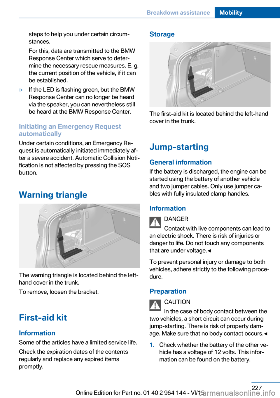
Warning triangle
The warning triangle is located behind the left-
hand cover in the trunk.
To remove, loosen the bracket.
First-aid kit InformationSome of the articles have a limited service life.
Check the expiration dates of the contents
regularly and replace any expired items
promptly.
Storage
The first-aid kit is located behind the left-hand
cover in the trunk.
Jump-starting
General information If the battery is discharged, the engine can be
started using the battery of another vehicle and two jumper cables. Only use jumper ca‐
bles with fully insulated clamp handles.
Information DANGER
Contact with live components can lead to
an electric shock. There is risk of injuries or
danger to life. Do not touch any components
that are under voltage.◀
To prevent personal injury or damage to both
vehicles, adhere strictly to the following proce‐
dure.
Preparation CAUTION
In the case of body contact between the
two vehicles, a short circuit can occur during jump-starting. There is risk of property dam‐
age. Make sure that no body contact occurs.◀
1.Check whether the battery of the other ve‐
hicle has a voltage of 12 volts. This infor‐
mation can be found on the battery.Seite 227Breakdown assistanceMobility227
Online Edition for Part no. 01 40 2 964 144 - VI/15
Page 228 of 253

2.Switch off the engine of the assisting vehi‐
cle.3.Switch off any electronic systems/power
consumers in both vehicles.
Starting aid terminals
WARNING
If the jumper cables are connected in the
incorrect order, sparks formation can occur.
There is risk of injuries. Pay attention to the
correct order during connection.◀
The so-called starting aid terminal in the en‐
gine compartment acts as the battery's posi‐
tive terminal.
The body ground or a special nut acts as the
battery negative terminal.
Connecting the cables
1.Pull off the lid of the BMW starting aid ter‐
minal.2.Attach one terminal clamp of the positive
jumper cable to the positive terminal of the
battery, or to the corresponding startingaid terminal of the vehicle providing assis‐
tance.3.Attach the terminal clamp on the other end
of the cable to the positive terminal of the
battery, or to the corresponding starting
aid terminal of the vehicle to be started.4.Attach one terminal clamp of the negative
jumper cable to the negative terminal of
the battery, or to the corresponding engine
or body ground of assisting vehicle.5.Attach the second terminal clamp to the
negative terminal of the battery, or to the
corresponding engine or body ground of
the vehicle to be started.
Starting the engine
Never use spray fluids to start the engine.
1.Start the engine of the assisting vehicle
and let it run for several minutes at an in‐
creased idle speed.2.Start the engine of the vehicle that is to be
started in the usual way.
If the first starting attempt is not success‐
ful, wait a few minutes before making an‐
other attempt in order to allow the dis‐
charged battery to recharge.3.Let both engines run for several minutes.4.Disconnect the jumper cables in the re‐
verse order.
Check the battery and recharge if needed.
Tow-starting and towing Information WARNING
Due to system limits, individual functions
can malfunction during tow-starting/towing
with the Intelligent Safety systems activated,
e.g. approach control warning with light brak‐
ing function. There is risk of an accident.
Seite 228MobilityBreakdown assistance228
Online Edition for Part no. 01 40 2 964 144 - VI/15
Page 232 of 253
In this way, the ignition remains switched
on, and a Check-Control message is dis‐
played.
CAUTION
Selector lever position P is automati‐
cally engaged when the ignition is
switched off. There is risk of property dam‐
age. Do not switch ignition off in car
washes.◀
The vehicle cannot be locked from the outside
when in selector lever position N. A signal
sounds when an attempt is made to lock the
vehicle.
To start the engine with Steptronic transmis‐
sion:
1.Depress the brake pedal.2.Press the Start/Stop button.
Pressing the Start/Stop button without step‐
ping on the brake turns the ignition off.
Selector lever positionSelector lever position P is engaged automati‐
cally:
▷When the ignition is switched off.▷After approx. 15 minutes.
Headlights
▷Do not rub dry and do not use abrasive or
acidic cleansers.▷Soak areas that have been dirtied e. g.,
from insects, with shampoo and wash off
with water.▷Thaw ice with de-icing spray; do not use an
ice scraper.
After washing the vehicle
After washing the vehicle, apply the brakes
briefly to dry them; otherwise, braking action
can be reduced and corrosion of the brake
discs can occur.
Completely remove all residues on the win‐
dows, to minimize loss of visibility due to
smearing and to reduce wiper noises and
wiper blade wear.
Vehicle care
Car care products The manufacturer of your vehicle recommends
using car care and cleaning products from
BMW.
WARNING
Cleansers can contain substances that
are dangerous and harmful to your health.
There is risk of injuries. When cleaning the in‐
terior, open the doors or windows. Only use
products intended for cleaning vehicles. Fol‐
low the instructions on the container.◀
Vehicle paint
Regular care contributes to driving safety and
value retention. Environmental influences in
areas with elevated air pollution or natural con‐
taminants, such as tree resin or pollen can af‐
fect the vehicle's paintwork. Tailor the fre‐
quency and extent of your car care to these
influences.
Aggressive substances such as spilled fuel, oil,
grease or bird droppings, must be removed im‐
mediately to prevent the finish from being al‐
tered or discolored.
Leather care
Remove dust from the leather often, using a
cloth or vacuum cleaner.
Otherwise, particles of dust and road grime
chafe in pores and folds, and lead to increased
wear and premature degradation of the leather
surface.
To guard against discoloration, such as from
clothing, provide leather care roughly every
two months.Seite 232MobilityCare232
Online Edition for Part no. 01 40 2 964 144 - VI/15
Page 243 of 253
BMW maintenance sys‐tem 215
Bonus range, ECO PRO 185
Bottle holder, see Cu‐ pholder 171
Brake assistant 126
Brake discs, break-in 176
Brake force display 125
Brake lights, adaptive 125
Brake lights, brake force dis‐ play 125
Brake pads, break-in 176
Braking, hints 178
Breakdown assistance 226
Break-in 176
Brightness of Control Dis‐ play 95
Bulb replacement 217
Bulb replacement, front 218
Bulb replacement, rear 221
Bulbs and lights 217
Button, RES 136
Button, Start/Stop 67
Bypassing, see Jump-start‐ ing 227
C
California Proposition 65 Warning 8
Camera lenses, care 234
Camera, rearview cam‐ era 145
Camera, Side View 149
Camera, Top View 148
Can holder, see Cu‐ pholder 171
Car battery 224
Car care products 232
Care, displays 234
Care, vehicle 232
Cargo 180
Cargo area 168
Cargo area, enlarging 168
Cargo area, storage compart‐ ments 172 Cargo cover 168
Cargo, securing 181
Cargo straps, securing cargo 181
Car key, see Remote con‐ trol 34
Carpet, care 234
Car wash 231
Catalytic converter, see Hot exhaust system 177
CBS Condition Based Serv‐ ice 215
CD/Multimedia, see user's manual for Navigation, En‐
tertainment and Communi‐
cation
Center armrest 171
Center console 16
Central locking system 40
Central screen, see Control Display 18
Changes, technical, see Own Safety 7
Changing parts 217
Changing wheels 223
Changing wheels/tires 201
Chassis number, see vehicle identification number 10
Check Control 83
Checking the oil level elec‐ tronically 209
Children, seating position 63
Children, transporting safely 63
Child restraint fixing sys‐ tem 63
Child restraint fixing system LATCH 65
Child restraint fixing systems, mounting 64
Child safety locks 66
Child seat, mounting 64
Child seats 63
Chrome parts, care 233
Cigarette lighter 165
Cleaning displays 234 Climate control 155, 158
Clock 87
Closing/opening via door lock 39
Closing/opening with remote control 37
Closing the tailgate with no- touch activation 44
Clothes hooks 172
Coasting 187
Coasting with engine decou‐ pled, coasting 187
Coasting with idling en‐ gine 187
Cockpit 14
Combination switch, see Turn signals 73
Combination switch, see Wiper system 74
Comfort Access 42
COMFORT program, Dy‐ namic Driving Control 131
Compartments in the doors 171
Compass 93
Compressor 203
Condensation on win‐ dows 157, 160
Condensation under the vehi‐ cle 179
Condition Based Service CBS 215
Confirmation signal 45
ConnectedDrive, see user's manual for Navigation, En‐
tertainment and Communi‐
cation
ConnectedDrive Services
Connecting electrical devi‐ ces 166
Continued driving with a flat tire 108 , 111
Control Display 18
Control Display, settings 94
Controller 19 Seite 243Everything from A to ZReference243
Online Edition for Part no. 01 40 2 964 144 - VI/15