2015 BMW X4 trunk
[x] Cancel search: trunkPage 181 of 253

Load
The maximum load is the sum of the weight of
the occupants and the cargo.
The greater the weight of the occupants, the
less cargo that can be transported.
Stowing cargo
▷Cover sharp edges and corners on the
cargo.▷Heavy cargo: stow as far forward as possi‐
ble, directly behind and at the bottom of
the rear passenger seat backrests.▷Very heavy cargo: when the rear seat is not
occupied, secure each of the outer safety
belts in the opposite buckle.▷If necessary, fold down the rear backrests
to stow cargo.▷Do not stack cargo above the top edge of
the backrests.Securing cargo
Lashing eyes in the cargo area
To secure the cargo there are four lashing
eyes in the cargo area.
Lashing eyes in the trunk with rails
To secure the cargo there are four movable
lashing eyes in the cargo area.
To slide the lashing eyes, press the button, ar‐
row 1. Make sure that the lashing eyes latch at
the new position.
The lashing eyes at the openings in the rails
can be removed.
Seite 181LoadingDriving tips181
Online Edition for Part no. 01 40 2 964 144 - VI/15
Page 182 of 253

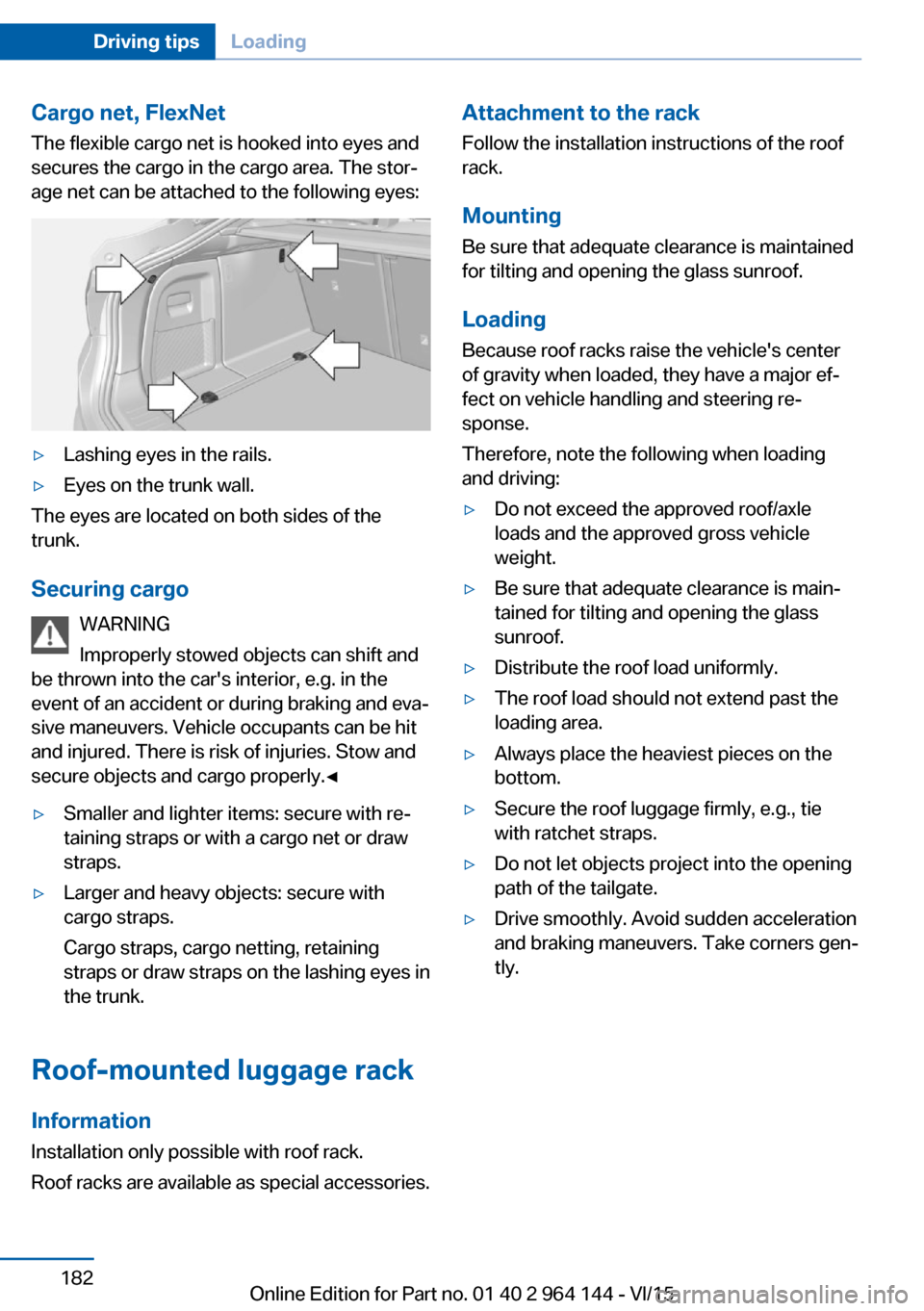
Cargo net, FlexNetThe flexible cargo net is hooked into eyes and
secures the cargo in the cargo area. The stor‐
age net can be attached to the following eyes:▷Lashing eyes in the rails.▷Eyes on the trunk wall.
The eyes are located on both sides of the
trunk.
Securing cargo WARNING
Improperly stowed objects can shift and
be thrown into the car's interior, e.g. in the
event of an accident or during braking and eva‐
sive maneuvers. Vehicle occupants can be hit
and injured. There is risk of injuries. Stow and
secure objects and cargo properly.◀
▷Smaller and lighter items: secure with re‐
taining straps or with a cargo net or draw
straps.▷Larger and heavy objects: secure with
cargo straps.
Cargo straps, cargo netting, retaining
straps or draw straps on the lashing eyes in
the trunk.
Roof-mounted luggage rack
Information
Installation only possible with roof rack.
Roof racks are available as special accessories.
Attachment to the rack Follow the installation instructions of the roof
rack.
Mounting
Be sure that adequate clearance is maintained
for tilting and opening the glass sunroof.
LoadingBecause roof racks raise the vehicle's centerof gravity when loaded, they have a major ef‐
fect on vehicle handling and steering re‐
sponse.
Therefore, note the following when loading
and driving:▷Do not exceed the approved roof/axle
loads and the approved gross vehicle
weight.▷Be sure that adequate clearance is main‐
tained for tilting and opening the glass
sunroof.▷Distribute the roof load uniformly.▷The roof load should not extend past the
loading area.▷Always place the heaviest pieces on the
bottom.▷Secure the roof luggage firmly, e.g., tie
with ratchet straps.▷Do not let objects project into the opening
path of the tailgate.▷Drive smoothly. Avoid sudden acceleration
and braking maneuvers. Take corners gen‐
tly.Seite 182Driving tipsLoading182
Online Edition for Part no. 01 40 2 964 144 - VI/15
Page 192 of 253

RefuelingVehicle features and options
This chapter describes all standard, country-
specific and optional features offered with the
series. It also describes features that are not
necessarily available in your car, e. g., due to
the selected options or country versions. This
also applies to safety-related functions and
systems. The respectively applicable country
provisions must be observed when using the
respective features and systems.
Information Observe the fuel recommendation, refer to
page 194, prior to refueling.
CAUTION
With a range of less than 30 miles/50 km
it is possible that the engine will no longer have
sufficient fuel. Engine functions are no longer
ensured. There is risk of property damage. Re‐
fuel promptly.◀
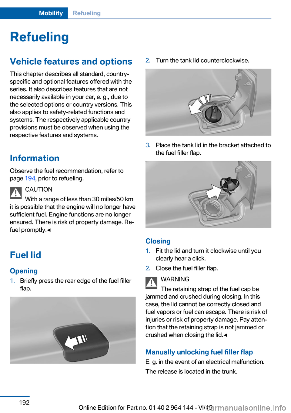
Fuel lidOpening1.Briefly press the rear edge of the fuel filler
flap.2.Turn the tank lid counterclockwise.3.Place the tank lid in the bracket attached to
the fuel filler flap.
Closing
1.Fit the lid and turn it clockwise until you
clearly hear a click.2.Close the fuel filler flap.
WARNING
The retaining strap of the fuel cap be
jammed and crushed during closing. In this
case, the lid cannot be correctly closed and
fuel vapors or fuel can escape. There is risk of
injuries or risk of property damage. Pay atten‐
tion that the retaining strap is not jammed or
crushed when closing the lid.◀
Manually unlocking fuel filler flapE. g. in the event of an electrical malfunction.
The release is located in the trunk.
Seite 192MobilityRefueling192
Online Edition for Part no. 01 40 2 964 144 - VI/15
Page 205 of 253

7.With the ignition turned on or the engine
running, switch on the compressor.
CAUTION
The compressor can overheat during ex‐
tended operation. There is risk of property
damage. Do not run the compressor for more
than 10 min.◀
Let the compressor run for approx. 3 to 8 mi‐
nutes to fill the tire with sealant and achieve a
tire inflation pressure of approx. 2.5 bar.
While the tire is being filled with sealant, the
tire inflation pressure may sporadically reach
approx. 5 bar. Do not switch off the compres‐
sor at this point.
If a tire inflation pressure of 2 bar is not
reached:
1.Switch off the compressor.2.Unscrew the filling hose from the wheel.3.Drive 33 ft/10 m forward and back to dis‐
tribute the sealant in the tire.4.Inflate the tire again using the compressor.
If a tire inflation pressure of 2 bar cannot be
reached, contact your dealer’s service cen‐
ter or another qualified service center or
repair shop.
Stowing the Mobility System
1.Unscrew the filling hose of the sealant con‐
tainer from the wheel.2.Unscrew the connection hose of the com‐
pressor from the sealant container.3.Connect the filling hose of the sealant con‐
tainer previously connected to the tirevalve with the available connector on the
sealant container.
This prevents leftover sealant from escap‐
ing from the container.4.Wrap the empty sealant container in suita‐
ble material to avoid dirtying the trunk.5.Stow the Mobility System back in the vehi‐
cle.
Distributing the sealant
Immediately drive approx. 5 miles/10 km to en‐
sure that the sealant is evenly distributed in the
tire.
Do not exceed a speed of 50 mph/80 km/h.
If possible, do not drive at speeds less than
12 mph/20 km/h.
To correct the tire inflation pressure
1.Stop at a suitable location.2.Screw the connection hose of the com‐
pressor directly onto the tire valve stem.3.Insert the connector into the power socket
inside the vehicle.4.Correct the tire inflation pressure to
2.5 bar.▷Increase pressure: with the ignition
turned on or the engine running, switch
on the compressor.▷To reduce the pressure: press the but‐
ton on the compressor.
Continuing the trip
Do not exceed the maximum permissible
speed of 50 mph/80 km/h.
Reinitialize the Flat Tire Monitor.
Reinitialize the Tire Pressure Monitor.
Replace the nonworking tire and the sealant
container of the Mobility System as soon as
possible.
Seite 205Wheels and tiresMobility205
Online Edition for Part no. 01 40 2 964 144 - VI/15
Page 217 of 253

Replacing componentsVehicle features and optionsThis chapter describes all standard, country-
specific and optional features offered with the
series. It also describes features that are not
necessarily available in your car, e. g., due to
the selected options or country versions. This
also applies to safety-related functions and
systems. The respectively applicable country
provisions must be observed when using the
respective features and systems.
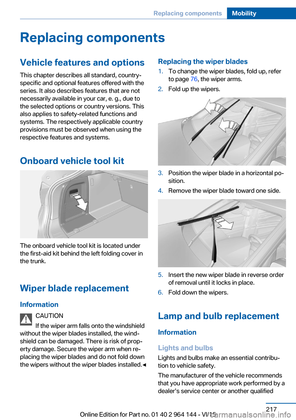
Onboard vehicle tool kit
The onboard vehicle tool kit is located under
the first-aid kit behind the left folding cover in
the trunk.
Wiper blade replacement
Information CAUTION
If the wiper arm falls onto the windshield
without the wiper blades installed, the wind‐ shield can be damaged. There is risk of prop‐
erty damage. Secure the wiper arm when re‐
placing the wiper blades and do not fold down
the wipers without the wiper blades installed.◀
Replacing the wiper blades1.To change the wiper blades, fold up, refer
to page 76, the wiper arms.2.Fold up the wipers.3.Position the wiper blade in a horizontal po‐
sition.4.Remove the wiper blade toward one side.5.Insert the new wiper blade in reverse order
of removal until it locks in place.6.Fold down the wipers.
Lamp and bulb replacement
Information
Lights and bulbs
Lights and bulbs make an essential contribu‐
tion to vehicle safety.
The manufacturer of the vehicle recommends
that you have appropriate work performed by a
dealer’s service center or another qualified
Seite 217Replacing componentsMobility217
Online Edition for Part no. 01 40 2 964 144 - VI/15
Page 225 of 253

Disposing of old batteriesHave old batteries disposed of by a
dealer’s service center or another
qualified service center or repair shop
or take them to a collection point.
Maintain the battery in an upright position for
transport and storage. Secure the battery so
that it does not tip over during transport.
Fuses Information WARNING
Incorrect and repaired fuses can overload
electrical lines and components. There is risk
of fire. Never attempt to repair a blown fuse
and do not replace a nonworking fuse with a
substitute of another color or amperage rat‐
ing.◀
Plastic tweezers and information on the fuse
types and locations are stored in the fuse box
in the trunk.
In the glove compartment
Swing the cover down, arrow.
In the trunk
Open the cover on the right side trim, arrow,
and remove the sound insulation.
Information on the fuse types and locations is
found on a separate sheet.
Seite 225Replacing componentsMobility225
Online Edition for Part no. 01 40 2 964 144 - VI/15
Page 227 of 253

steps to help you under certain circum‐
stances.
For this, data are transmitted to the BMW
Response Center which serve to deter‐
mine the necessary rescue measures. E. g.
the current position of the vehicle, if it can
be established.▷If the LED is flashing green, but the BMW
Response Center can no longer be heard
via the speaker, you can nevertheless still
be heard at the BMW Response Center.
Initiating an Emergency Request
automatically
Under certain conditions, an Emergency Re‐
quest is automatically initiated immediately af‐
ter a severe accident. Automatic Collision Noti‐
fication is not affected by pressing the SOS
button.
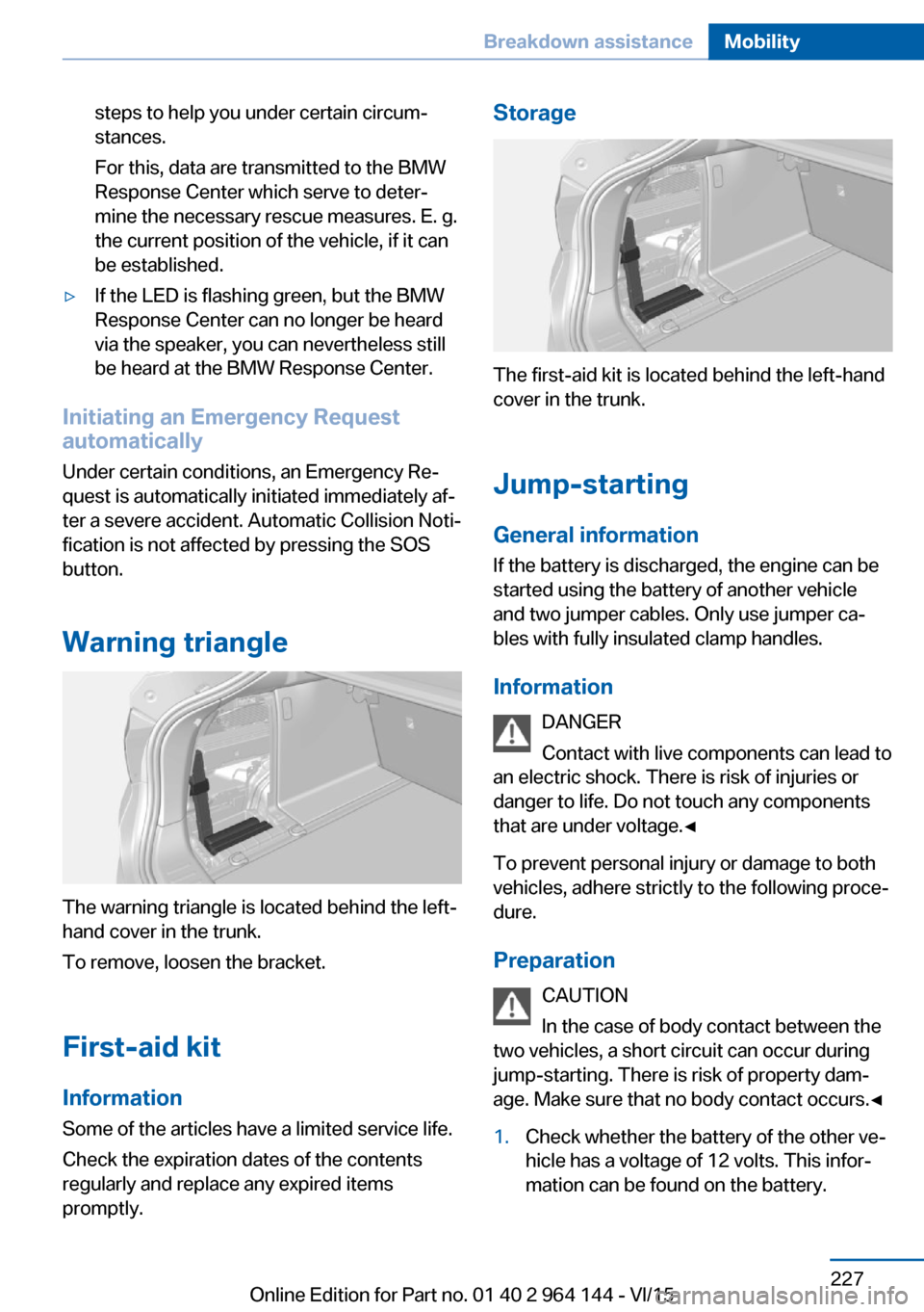
Warning triangle
The warning triangle is located behind the left-
hand cover in the trunk.
To remove, loosen the bracket.
First-aid kit InformationSome of the articles have a limited service life.
Check the expiration dates of the contents
regularly and replace any expired items
promptly.
Storage
The first-aid kit is located behind the left-hand
cover in the trunk.
Jump-starting
General information If the battery is discharged, the engine can be
started using the battery of another vehicle and two jumper cables. Only use jumper ca‐
bles with fully insulated clamp handles.
Information DANGER
Contact with live components can lead to
an electric shock. There is risk of injuries or
danger to life. Do not touch any components
that are under voltage.◀
To prevent personal injury or damage to both
vehicles, adhere strictly to the following proce‐
dure.
Preparation CAUTION
In the case of body contact between the
two vehicles, a short circuit can occur during jump-starting. There is risk of property dam‐
age. Make sure that no body contact occurs.◀
1.Check whether the battery of the other ve‐
hicle has a voltage of 12 volts. This infor‐
mation can be found on the battery.Seite 227Breakdown assistanceMobility227
Online Edition for Part no. 01 40 2 964 144 - VI/15
Page 239 of 253

Weights
X4 xDrive28iApproved gross vehicle weightlbs/kg5,060/2,295Loadlbs/kg910/413Approved front axle loadlbs/kg2,370/1,075Approved rear axle loadlbs/kg2,820/1,279Approved roof load capacitylbs/kg220/100Cargo area capacitycu ft17.7–49.4Canada: trunk capacityliters500–1,400
X4 xDrive35iApproved gross vehicle weightlbs/kg5,180/2,350Loadlbs/kg910/413Approved front axle loadlbs/kg2,490/1,129Approved rear axle loadlbs/kg2,820/1,279Approved roof load capacitylbs/kg220/100Cargo area capacitycu ft17.7–49.4Canada: trunk capacityliters500–1,400
Capacities
US gal/litersNotesFuel tank, approx.17.7/67Fuel quality, refer to
page 194Seite 239Technical dataReference239
Online Edition for Part no. 01 40 2 964 144 - VI/15