2015 BMW X4 height
[x] Cancel search: heightPage 61 of 253
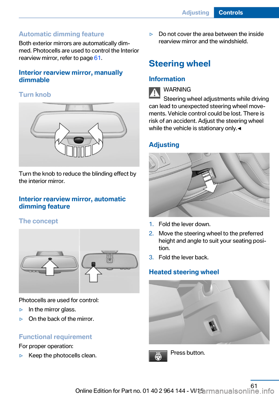
Automatic dimming featureBoth exterior mirrors are automatically dim‐
med. Photocells are used to control the Interior
rearview mirror, refer to page 61.
Interior rearview mirror, manually
dimmable
Turn knob
Turn the knob to reduce the blinding effect by
the interior mirror.
Interior rearview mirror, automaticdimming feature
The concept
Photocells are used for control:
▷In the mirror glass.▷On the back of the mirror.
Functional requirement For proper operation:
▷Keep the photocells clean.▷Do not cover the area between the inside
rearview mirror and the windshield.
Steering wheel
Information WARNING
Steering wheel adjustments while driving
can lead to unexpected steering wheel move‐
ments. Vehicle control could be lost. There is
risk of an accident. Adjust the steering wheel
while the vehicle is stationary only.◀
Adjusting
1.Fold the lever down.2.Move the steering wheel to the preferred
height and angle to suit your seating posi‐
tion.3.Fold the lever back.
Heated steering wheel
Press button.
Seite 61AdjustingControls61
Online Edition for Part no. 01 40 2 964 144 - VI/15
Page 64 of 253
securely against the backrest. If possible, ad‐
just the backrest tilt for all affected backrests
and correctly adjust the seats. Make sure that
seats and backrests are securely engaged. If
possible, adjust the height of the head re‐
straints or remove them.◀
Installing child restraint
systems
Information Pay attention to the specifications of the child
restraint system manufacturer when selecting,
installing, and using child restraint systems.
WARNING
The stability of the child restraint system
is limited or compromised with incorrect seat
adjustment or improper installation of the child
seat. There is risk of injuries or danger to life.
Make sure that the child restraint system fits
securely against the backrest. If possible, ad‐
just the backrest tilt for all affected backrests
and correctly adjust the seats. Make sure that
seats and backrests are securely engaged. If
possible, adjust the height of the head re‐
straints or remove them.◀
On the front passenger seat
Deactivating airbags WARNING
Active front-seat passenger airbags can
injure a child in a child restraint system when
the airbags are activated. There is risk of inju‐
ries. Make sure that the front-seat passenger
airbags are deactivated and that the PASSEN‐
GER AIRBAG OFF indicator lamp lights up.◀
After installing a child restraint system in the
front passenger seat, make sure that the front,
knee and side airbags on the front passenger
side are deactivated.Deactivate the front-seat passenger airbags
automatically, refer to page 105.
Seat position and height
Before installing a child restraint system, move
the front passenger seat as far back as possi‐
ble and adjust its height to the highest and
thus best possible position for the belt and to
offer optimal protection in the event of an acci‐
dent.
If the upper anchorage of the safety belt is lo‐
cated in front of the belt guide of the child seat,
move the passenger seat carefully forward un‐
til the best possible belt guide position is
reached.
Backrest width Adjustable backrest width: before installing a
child restraint system in the front passenger
seat, open the backrest width completely. Do
not change the backrest width again and do
not call up a memory position.
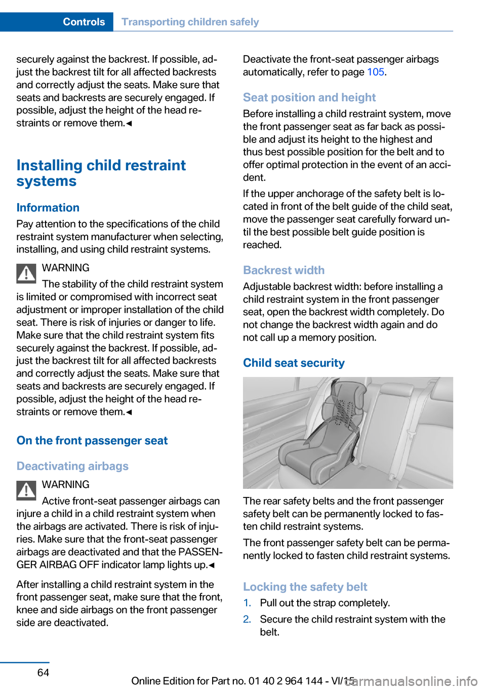
Child seat security
The rear safety belts and the front passenger
safety belt can be permanently locked to fas‐
ten child restraint systems.
The front passenger safety belt can be perma‐
nently locked to fasten child restraint systems.
Locking the safety belt
1.Pull out the strap completely.2.Secure the child restraint system with the
belt.Seite 64ControlsTransporting children safely64
Online Edition for Part no. 01 40 2 964 144 - VI/15
Page 96 of 253
The conceptThis system projects important information
into the driver's field of vision, e. g., the speed.
The driver can get information without averting
his or her eyes from the road.
Information
Follow the instructions for cleaning the Head-
up Display, refer to page 234.
Display visibility The visibility of the displays in the Head-up
Display is influenced by the following factors:▷Certain sitting positions.▷Objects on the cover of the Head-up Dis‐
play.▷Sunglasses with certain polarization filters.▷Wet roads.▷Unfavorable light conditions.
If the image is distorted, have the basic set‐
tings checked by a dealer’s service center or
another qualified service center or repair shop.
Switching on/off
1."Settings"2."Head-Up Display"3."Head-Up Display"
Display
Overview
The following information is displayed on the
Head-up Display:
▷Speed.▷Navigation system.▷Check Control messages.▷Selection list from the instrument cluster.▷Driver assistance systems.
Some of this information is only displayed
briefly as needed.
Selecting displays in the Head-up Display
On the Control Display:1."Settings"2."Head-Up Display"3."Displayed information"4.Select the desired displays in the Head-up
Display.
Settings are stored for the profile currently
used.
Setting the brightness The brightness is automatically adjusted to the
ambient brightness.
The basic setting can be adjusted manually.
On the Control Display:
1."Settings"2."Head-Up Display"3."Brightness"4.Turn the controller until the desired bright‐
ness is set.5.Press the controller.
When the low beams are activated, the bright‐
ness of the Head-up Display can be addition‐
ally influenced using the instrument lighting.
Settings are stored for the profile currently
used.
Adjusting the height
On the Control Display:
1."Settings"2."Head-Up Display"3."Height"4.Turn the controller until the desired height
is reached.5.Press the controller.
Settings are stored for the profile currently
used.
Seite 96ControlsDisplays96
Online Edition for Part no. 01 40 2 964 144 - VI/15
Page 169 of 253
and correctly adjust the seats. Make sure that
seats and backrests are securely engaged. If
possible, adjust the height of the head re‐
straints or remove them.◀
WARNING
With an unlocked backrest, an unsecured
load can be thrown into the car's interior, e.g.
in case of an accident, braking or evasive ma‐
neuver. There is risk of injuries. Make sure that
the backrest engages into the locking after
folding it back.◀
WARNING
With a rear backrest that is not locked,
the protective function of the middle safety
belt is not guaranteed. There is risk of injuries
or danger to life. If you are using the middle safety belt, lock the wider rear backrest.◀
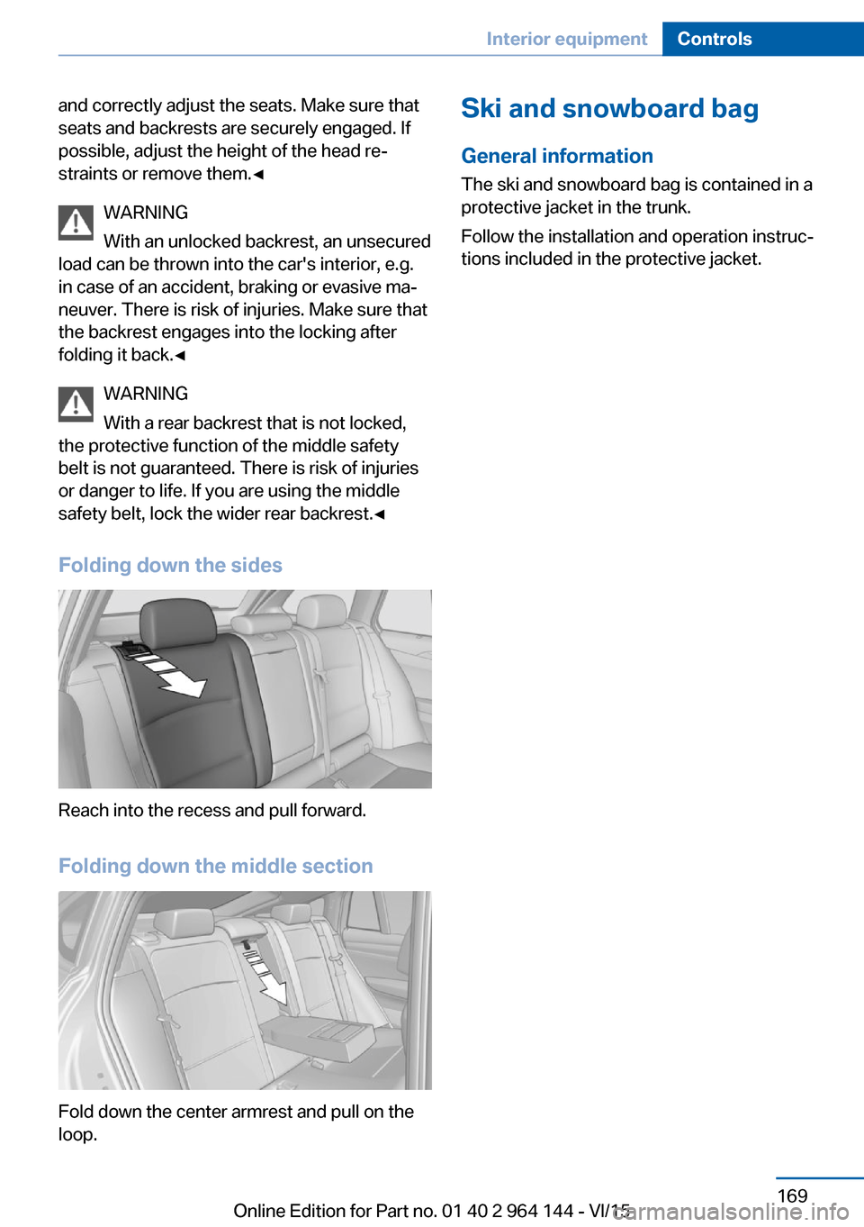
Folding down the sides
Reach into the recess and pull forward.
Folding down the middle section
Fold down the center armrest and pull on the
loop.
Ski and snowboard bag
General information
The ski and snowboard bag is contained in a
protective jacket in the trunk.
Follow the installation and operation instruc‐
tions included in the protective jacket.Seite 169Interior equipmentControls169
Online Edition for Part no. 01 40 2 964 144 - VI/15
Page 178 of 253
transmission. There is risk of property damage.
When driving through water, do not exceed the
maximum indicated water level and the maxi‐
mum speed for driving through water.◀
Drive though calm water only and only if it is
not deeper than 19.6 inches/50 cm and at this
height, no faster than walking speed, up to
3 mph/5 km/h.
Braking safely Your vehicle is equipped with ABS as a stand‐
ard feature.
Applying the brakes fully is the most effective
way of braking in situations needed.
Steering is still responsive. You can still avoid
any obstacles with a minimum of steering ef‐
fort.
Pulsation of the brake pedal and sounds from
the hydraulic circuits indicate that ABS is in its
active mode.
In certain braking situations, the perforated
brake discs can cause functional problems.
However, this has no effect on the perform‐
ance and operational reliability of the brake.
Objects in the movement area around
pedals and floor area
WARNING
Objects in the driver's floor area can limit
the pedal distance or block a depressed pedal.
There is risk of an accident. Stow objects in
the vehicle such that they are secured and
cannot enter into the driver's floor area. Use
floor mats that are suitable for the vehicle and
can be safely attached to the floor. Do not use
loose floor mats and do not layer several floor
mats. Make sure that there is sufficient clear‐
ance for the pedals. Ensure that the floor mats
are securely fastened again after they were re‐
moved, e.g. for cleaning.◀Driving in wet conditions
When roads are wet, salted, or in heavy rain,
press brake pedal ever so gently every few
miles.
Ensure that this action does not endanger
other traffic.
The heat generated in this process helps dry
the brake discs and pads.
In this way braking efficiency will be available
when you need it.
Hills WARNING
Light but consistent brake pressure can
lead to high temperatures, brakes wearing out
and possibly even brake failure. There is risk of
an accident. Avoid placing excessive stress on
the brake system.◀
WARNING
In idle or with the engine switched off,
safety-relevant functions are restricted or not
available anymore, e.g. braking effect of the
engine or braking force and steering support.
There is risk of an accident. Do not drive in idle
or with the engine switched off.◀
Drive long or steep downhill gradients in the
gear that requires least braking efforts. Other‐
wise the brakes may overheat and reduce
brake efficiency.
You can increase the engine's braking effect
by shifting down, going all the way to first gear,
if needed.
Brake disc corrosion
Corrosion on the brake discs and contamina‐
tion on the brake pads are furthered by the fol‐
lowing circumstances:▷Low mileage.▷Extended periods when the vehicle is not
used at all.▷Infrequent use of the brakes.Seite 178Driving tipsThings to remember when driving178
Online Edition for Part no. 01 40 2 964 144 - VI/15
Page 200 of 253
cantly from the norm due to variations in driv‐
ing habits, service practices and differences in
road characteristics and climate.
Traction
The traction grades, from highest to lowest,
are AA, A, B, and C.
Those grades represent the tire's ability to
stop on wet pavement as measured under
controlled conditions on specified government
test surfaces of asphalt and concrete. A tire
marked C may have poor traction performance.
The traction grade assigned to this tire is
based on straight-ahead braking traction tests,
and does not include acceleration, cornering,
hydroplaning, or peak traction characteristics.
Temperature
The temperature grades are A, the highest, B, and C, representing the tire's resistance to the
generation of heat and its ability to dissipate
heat when tested under controlled conditions
on a specified indoor laboratory test wheel.
Sustained high temperature can cause the ma‐
terial of the tire to degenerate and reduce tire
life, and excessive temperature can lead to
sudden tire failure. The grade C corresponds
to a level of performance which all passenger
car tires must meet under the Federal Motor
Vehicle Safety Standard No. 109. Grades Band
A represent higher levels of performance on
the laboratory test wheel than the minimum re‐
quired by law.
WARNING
The temperature grade for this tire is es‐
tablished for a tire that is properly inflated and
not overloaded. Excessive speed, underinfla‐
tion, or excessive loading, either separately or
in combination, can cause heat buildup and
possible tire failure.◀RSC – Run-flat tires
Run-flat tires, refer to page 202, are labeled
with a circular symbol containing the letters
RSC marked on the sidewall.
M+S Winter and all-season tires with better cold
weather performance than summer tires.
Tire tread Summer tires
Do not drive with a tire tread depth of less than
0.12 in/3 mm.
There is an increased danger of hydroplaning if
the tire tread depth is less than 0.12 in/3 mm.
Winter tires Do not drive with a tire tread depth of less than
0.16 in/4 mm.
Below a tread depth of 0.16 in/4 mm, tires are
less suitable for winter operation.
Minimum tread depth
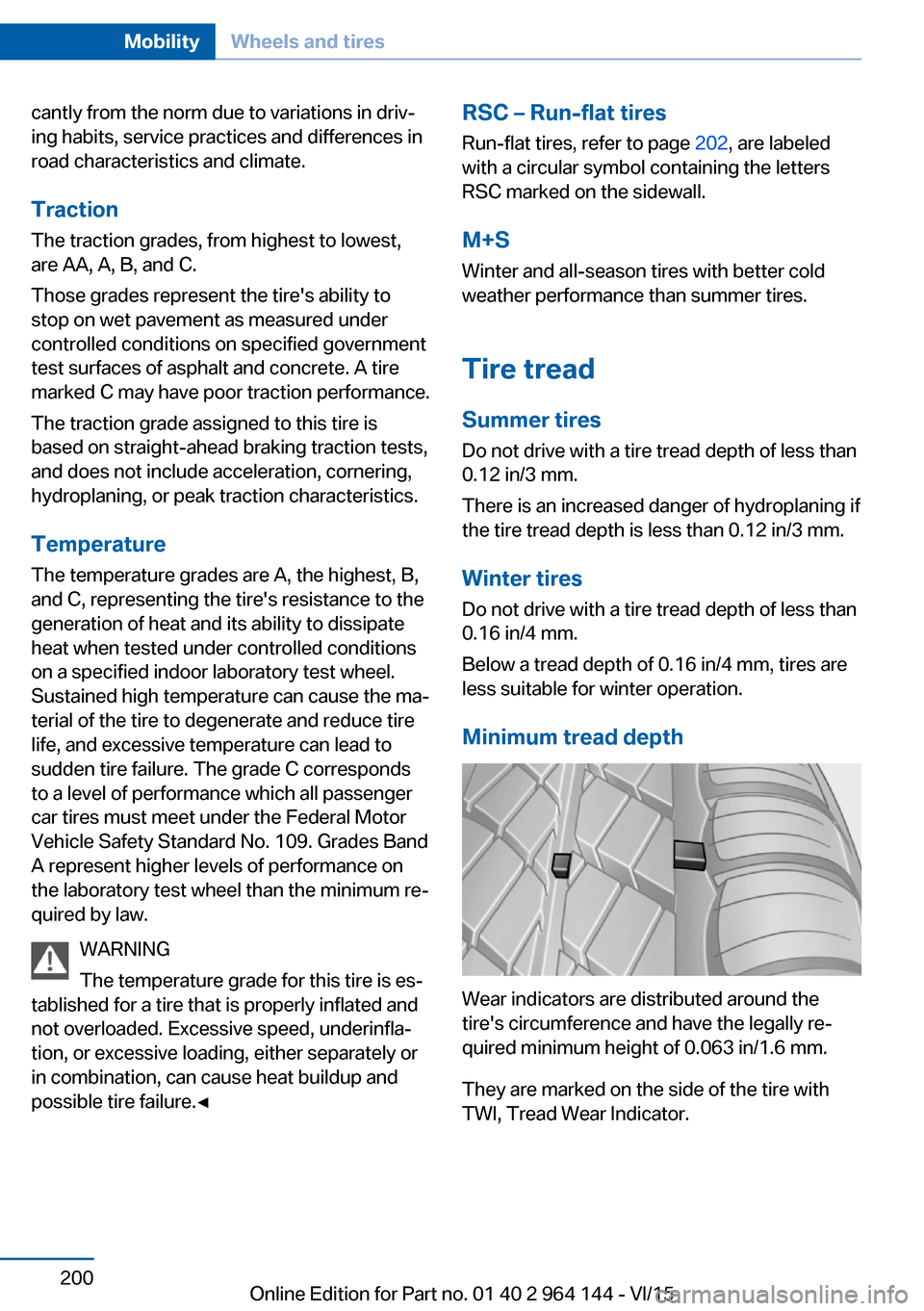
Wear indicators are distributed around the
tire's circumference and have the legally re‐
quired minimum height of 0.063 in/1.6 mm.
They are marked on the side of the tire with
TWI, Tread Wear Indicator.
Seite 200MobilityWheels and tires200
Online Edition for Part no. 01 40 2 964 144 - VI/15
Page 208 of 253
CAUTION
Folded-away wipers can be jammed
when the hood is opened. There is risk of
property damage. Make sure that the wipers
with the wiper blades mounted are folded
down onto the windshield before opening the
hood.◀
WARNING
There are protruding parts, e.g. lock
hook, on the inside of the hood. There is risk of
injuries. If the hood is open, pay attention to
protruding parts and keep these areas clear.◀
WARNING
An incorrectly locked hood can open
while driving and restrict visibility. There is risk
of an accident. Stop immediately and correctly
close the hood.◀
WARNING
Body parts can be jammed on opening
and closing the hood. There is risk of injuries.
Make sure that the area of movement of the
hood is clear during opening and closing.◀
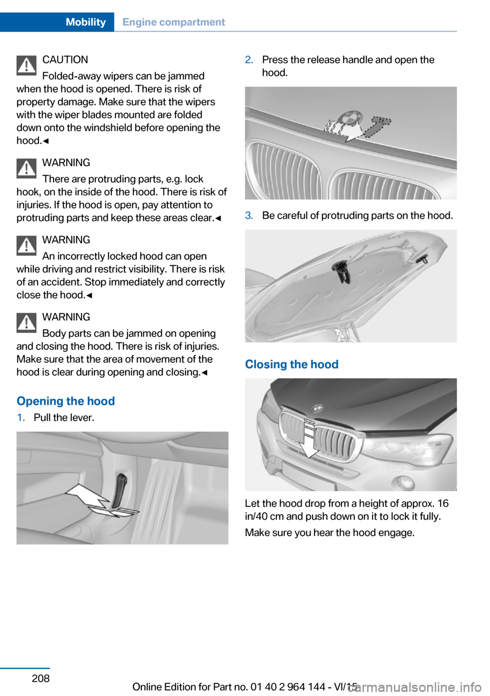
Opening the hood1.Pull the lever.2.Press the release handle and open the
hood.3.Be careful of protruding parts on the hood.
Closing the hood
Let the hood drop from a height of approx. 16
in/40 cm and push down on it to lock it fully.
Make sure you hear the hood engage.
Seite 208MobilityEngine compartment208
Online Edition for Part no. 01 40 2 964 144 - VI/15
Page 238 of 253

Technical dataVehicle features and options
This chapter describes all standard, country-
specific and optional features offered with the
series. It also describes features that are not
necessarily available in your car, e. g., due tothe selected options or country versions. This
also applies to safety-related functions and
systems. The respectively applicable country
provisions must be observed when using the
respective features and systems.
Information
The technical data and specifications in this
Owner's Manual are used as guidance values.
The vehicle-specific data can deviate from this,
for example, due to the selected special equip‐
ment, country version or country-specific
measurement method. Detailed values can befound in the approval documents, on labels on
the vehicle or can be obtained from a dealer’s
service center or another qualified service cen‐
ter or repair shop.
The information in the vehicle documents al‐
ways has priority.
Dimensions
The dimensions can vary depending on the
model version, equipment or country-specific
measurement method.
The specified heights do not take into account
attached parts, for example, a roof antenna,roof racks or spoiler. The heights can deviate,
for example, due to the selected special equip‐
ment, tires, load and chassis version. X4Width with mirrorsinches/mm82.3/2,089Width without mirrorsinches/mm74.1/1,881Heightinches/mm63.9/1,624Lengthinches/mm184.3/4,680Wheelbaseinches/mm110.6/2,810Smallest turning radius diam.ft/m39/11.9Seite 238ReferenceTechnical data238
Online Edition for Part no. 01 40 2 964 144 - VI/15