2015 BMW I8 tow bar
[x] Cancel search: tow barPage 133 of 224

▷For persons with certain clothing, e.g.
coats.▷With external interference of the ultra‐
sound, e.g. from passing vehicles or loud
machines.▷When sensors are dirty, iced over, dam‐
aged or out of position.▷Under certain weather conditions such as
high relative humidity, rain, snowfall, ex‐
treme heat or strong wind.▷With tow bars and trailer couplings of other
vehicles.▷With thin or wedge-shaped objects.▷With moving objects.▷With elevated, protruding objects such as
ledges or cargo.▷With objects with corners and sharp edges.▷With objects with a fine surface structure
such as fences.▷For objects with porous surfaces.
Low objects already displayed, e.g., curbs, can
move into the blind area of the sensors before
or after a continuous tone sounds.
False warnings
PDC may issue a warning under the following conditions even though there is no obstacle
within the detection range:
▷In heavy rain.▷When sensors are very dirty or covered
with ice.▷When sensors are covered in snow.▷On rough road surfaces.▷On uneven surfaces, such as speed
bumps.▷In large buildings with right angles and
smooth walls, e.g., in underground ga‐
rages.▷In automatic car washes.▷Through heavy pollution.▷Due to other ultrasound sources, e.g.,
sweeping machines, high pressure steam
cleaners or neon lights.
Malfunction
A Check Control message is displayed.
Red symbol is displayed, and the range
of the sensors is dimmed on the Con‐
trol Display.
PDC has failed. Have the system checked.
To ensure full functionality:
▷Keep the sensors clean and free of ice.▷dimmedDo not put any stickers on sen‐
sors.▷When using high-pressure washers, do not
spray the sensors for long periods and
maintain a distance of at least 12 in/30 cm.
Surround View
The concept Surround View comprises various camera as‐
sistance systems that help the driver when
parking, maneuvering, and at complex exits
and intersections.
▷Rearview camera, refer to page 117▷Top View, refer to page 120.▷Side View, refer to page 122.
Rearview camera
The concept The rearview camera provides assistance in
parking and maneuvering backwards. The area
behind the vehicle is shown on the Control
Display.
Seite 117Driving comfortControls117
Online Edition for Part no. 01 40 2 960 891 - II/15
Page 171 of 224

4.Set rate begin. Turn the controller until the
desired time is set and press the controller.5.Set rate end. Turn the controller until the
desired time is set and press the controller.
Setting charging via a
Level 1 charging cable
Depending on the electrical mains, the vehicle
must be charged with a different charging cur‐
rent strength, refer to page 150.
1."Settings"2."Charging"3."AC charging power:"
Settings are stored. When you change charg‐
ing locations you also might need to change
the setting for charging.
Set the charge current strength at other
household sockets to "Low".
Stopping charging process The charging operation can be stopped at any
time by removing the charging cable and con‐
tinued at a later time by connecting the charg‐
ing cable in order to use other loads on the
power connection or to prevent simultaneous
high power from multiple loads.
The charging operation is interrupted when the
vehicle is unlocked and automatically resumed
after a brief time or when it is locked.
Continue charging operation If the charging operation is interrupted, e.g.,
through a temporary power failure, the charg‐
ing operation is automatically continued after
the interruption.
Terminating charging process
1.Removing the charging cable from the ve‐
hicle, refer to page 152.2.Stow the charging cable as required.3.Close the charging port flap.4.Lock vehicle if it is unlocked.Displays in the instrument
cluster
The charging state indicator light, refer to page 77, shows the charging state of the high-
voltage battery in the instrument cluster, if op‐
erating readiness is switched on. If all seg‐
ments are filled, the high-voltage battery is
fully charged.
Even if no segments are filled, the high-voltage
system is still under high voltage.
Information regarding the charging process are
shown on the charging screen, refer to
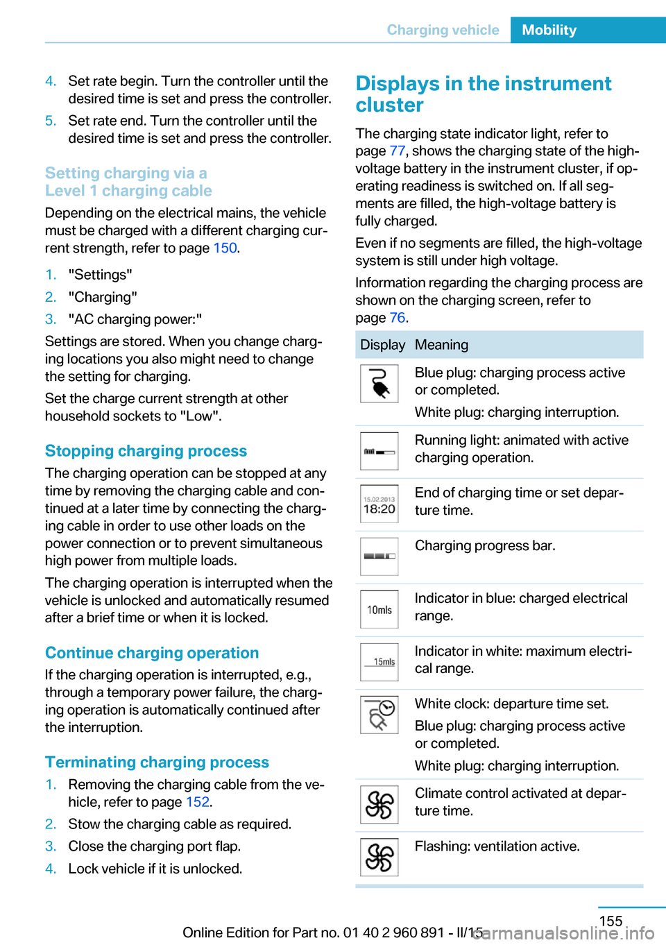
page 76.DisplayMeaningBlue plug: charging process active
or completed.
White plug: charging interruption.Running light: animated with active
charging operation.End of charging time or set depar‐
ture time.Charging progress bar.Indicator in blue: charged electrical
range.Indicator in white: maximum electri‐
cal range.White clock: departure time set.
Blue plug: charging process active
or completed.
White plug: charging interruption.Climate control activated at depar‐
ture time.Flashing: ventilation active.Seite 155Charging vehicleMobility155
Online Edition for Part no. 01 40 2 960 891 - II/15
Page 186 of 224

4.Slide the sealing container upright into the
holder on the compressor housing, ensur‐
ing that it engages audibly.5.Screw the connection hose onto the tire
valve of the defective wheel.6.With the compressor switched off, insert
the plug into a power socket inside the ve‐
hicle.7.With operating readiness or drive readi‐
ness switched on, reel on the compressor.
Switch off the compressor after 10 mi‐
nutes
Do not allow the compressor to run longer than
10 minutes; otherwise, the device will overheat
and may be damaged.◀
Let the compressor run for approx. 3 to 8 mi‐
nutes to fill the tire with sealant and achieve a
tire inflation pressure of approx. 2.5 bar.
While the tire is being filled with sealant, the
tire inflation pressure may sporadically reach
approx. 5 bar. Do not reel off the compressor at
this point.
If a tire inflation pressure of 2 bar is not
reached:
1.Switch off the compressor.2.Unscrew the filling hose from the wheel.3.Drive 33 ft/10 m forward and back to dis‐
tribute the sealant in the tire.4.Inflate the tire again using the compressor.
If a tire inflation pressure of 2 bar cannot be
reached, contact your service center.
Stowing the Mobility System
1.Remove the connection hose of the seal‐
ant container from the wheel.2.Remove the connection hose from the
sealant container.Seite 170MobilityWheels and tires170
Online Edition for Part no. 01 40 2 960 891 - II/15
Page 187 of 224

3.Wrap the empty sealant container and con‐
nection hose in suitable material to avoid
dirtying the cargo area.4.Stow the Mobility System back in the vehi‐
cle.
Distributing the sealant
Immediately drive approx. 5 miles/10 km to en‐
sure that the sealant is evenly distributed in the
tire.
Do not exceed a speed of 50 mph/80 km/h.
If possible, do not drive at speeds less than
12 mph/20 km/h.
To correct the tire inflation pressure
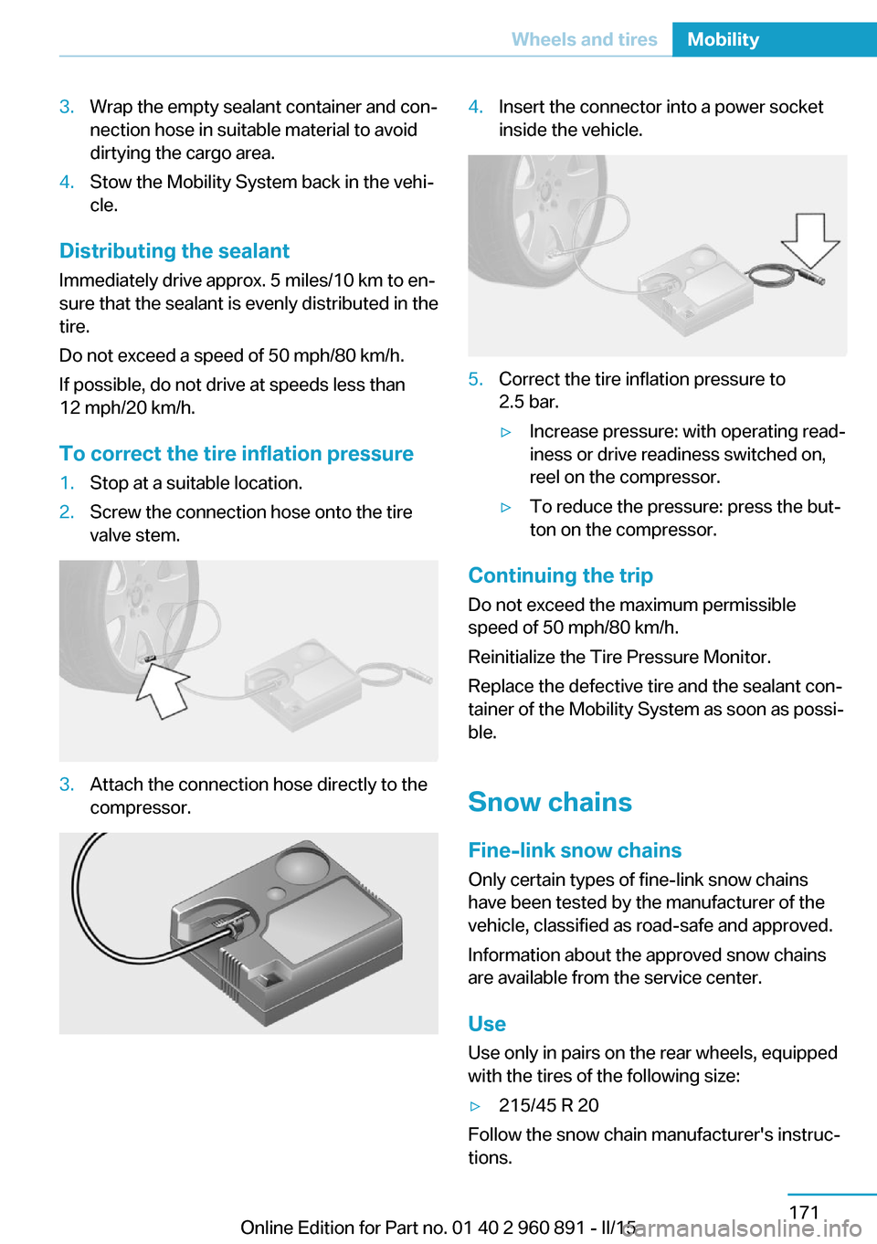
1.Stop at a suitable location.2.Screw the connection hose onto the tire
valve stem.3.Attach the connection hose directly to the
compressor.4.Insert the connector into a power socket
inside the vehicle.5.Correct the tire inflation pressure to
2.5 bar.▷Increase pressure: with operating read‐
iness or drive readiness switched on,
reel on the compressor.▷To reduce the pressure: press the but‐
ton on the compressor.
Continuing the trip
Do not exceed the maximum permissible
speed of 50 mph/80 km/h.
Reinitialize the Tire Pressure Monitor.
Replace the defective tire and the sealant con‐
tainer of the Mobility System as soon as possi‐
ble.
Snow chains Fine-link snow chains
Only certain types of fine-link snow chains
have been tested by the manufacturer of the
vehicle, classified as road-safe and approved.
Information about the approved snow chains
are available from the service center.
Use
Use only in pairs on the rear wheels, equipped
with the tires of the following size:
▷215/45 R 20
Follow the snow chain manufacturer's instruc‐
tions.
Seite 171Wheels and tiresMobility171
Online Edition for Part no. 01 40 2 960 891 - II/15