2015 BMW I8 remote control
[x] Cancel search: remote controlPage 106 of 224
Language
Setting the language
To set the language on the Control Display:1."Settings"2."Language/Units"3."Language:"4.Select the desired language.
Settings are stored for the profile currently in
use.
Setting the voice dialog
Voice dialog for the voice activation system,
refer to page 27.
Units of measure
Setting the units of measure
To set the units for fuel consumption, route/
distance and temperature:
1."Settings"2."Language/Units"3.Select the desired menu item.4.Select the desired unit.
Settings are stored for the profile currently in
use.
Brightness
Setting the brightness
To set the brightness of the Control Display:
1."Settings"2."Control display"3."Brightness"4.Turn the controller until the desired bright‐
ness is set.5.Press the controller.
Settings are stored for the profile currently in
use.
Depending on the light conditions, the bright‐
ness settings may not be clearly visible.
Activating/deactivating display of the
current vehicle position
If GPS geolocation has been activated, the cur‐
rent vehicle position can be displayed in the
BMW i Remote App or in the ConnectedDrive
customer portal.1."Settings"2."GPS tracking"3."GPS tracking"
Head-up Display
The concept
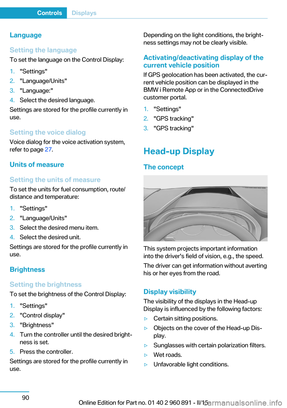
This system projects important information
into the driver's field of vision, e.g., the speed.
The driver can get information without averting
his or her eyes from the road.
Display visibility The visibility of the displays in the Head-up
Display is influenced by the following factors:
▷Certain sitting positions.▷Objects on the cover of the Head-up Dis‐
play.▷Sunglasses with certain polarization filters.▷Wet roads.▷Unfavorable light conditions.Seite 90ControlsDisplays90
Online Edition for Part no. 01 40 2 960 891 - II/15
Page 144 of 224
With the BMW i Remote App, refer to
page 128, the standing air conditioning can be
switched on.
The system switches off automatically after a
certain period of time.
If stationary climate control is used during the
charging process, less air conditioning ca‐
pacity will be required while driving. This opti‐
mizes the range.
Functional requirements▷When the departure time is preselected:
depends on internal, external and set tem‐
perature.▷Direct operation via iDrive: any external
temperature.▷Charging cable connected or high-voltage
battery sufficiently charged.▷Motor switched off and/or drive readiness
deactivated.▷The vents are open to allow air to flow out.
Switching on/off directly
On the Control Display:
1."Settings"2."Climate"3."Activate comfort climate control"
The symbol on the automatic climate con‐
trol flashes if the stationary climate control is
switched on.
Activate climate control at departuretime
The reel-on time is automatically determined
based on the temperature. The system
promptly switches on before the selected de‐
parture time.
On the Control Display:
1."Settings"2."Departure time"3."Departure 1:"4."Precondition for departure time"5.Set and activate Desired departure time,
refer to page 156.
The symbol on the automatic climate con‐
trol lights up when the departure time is acti‐
vated.
The symbol on the automatic climate con‐
trol flashes when the stationary climate control
has been switched on.
If drive readiness is switched off, changes can
be made on the Control Display. Departure
time can only be changed once. Scheduled de‐
parture times are not adjusted. Settings for cli‐
mate control and charging operation are also
applied for scheduled departure times.
Activating with BMW i Remote App
Using the BMW i Remote App, the system can
be directly switched on or via a preset depar‐
ture time.
Seite 128ControlsClimate control128
Online Edition for Part no. 01 40 2 960 891 - II/15
Page 145 of 224
Interior equipmentVehicle features and optionsThis chapter describes all standard, country-
specific and optional features offered with the
series. It also describes features that are not
necessarily available in your car, e. g., due to
the selected options or country versions. This
also applies to safety-related functions and
systems. The respectively applicable country
provisions must be observed when using the
respective features and systems.
Universal Integrated Remote Control
The concept The universal garage door opener can operate
up to 3 functions of remote-controlled sys‐
tems such as garage door drives or lighting
systems. The universal garage door opener re‐
places up to 3 different hand-held transmitters.
To operate the remote control, the buttons on
the interior rearview mirror must be program‐
med with the desired functions. The hand-held
transmitter for the particular system is required
in order to program the remote control.
During programming
During programming and before activat‐
ing a device using the universal garage door
opener, ensure that there are no people, ani‐
mals or objects in the area of the remote-con‐
trolled device; otherwise, there is a risk of in‐
jury or damage.
Also follow the safety instructions of the hand-
held transmitter.◀
Before selling the vehicle, delete the stored
functions for the sake of security.Compatibility
If this symbol is printed on the packag‐
ing or in the instructions of the system
to be controlled, the system is gener‐
ally compatible with the universal garage door opener.
If you have any questions, please contact:▷Your service center.▷www.homelink.com on the Internet.
HomeLink is a registered trademark of Gentex
Corporation.
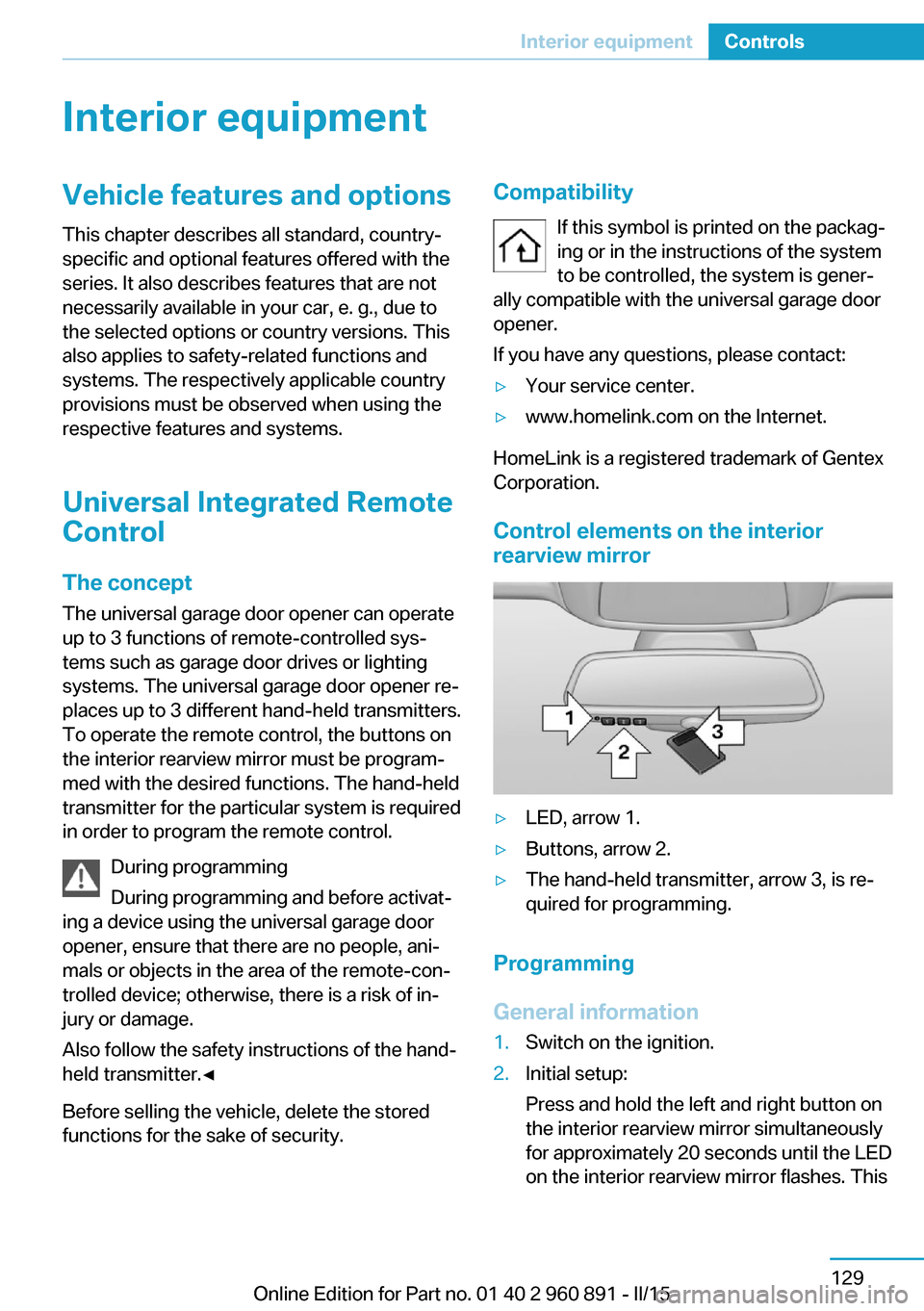
Control elements on the interior
rearview mirror
▷LED, arrow 1.▷Buttons, arrow 2.▷The hand-held transmitter, arrow 3, is re‐
quired for programming.
Programming
General information
1.Switch on the ignition.2.Initial setup:
Press and hold the left and right button on
the interior rearview mirror simultaneously
for approximately 20 seconds until the LED
on the interior rearview mirror flashes. ThisSeite 129Interior equipmentControls129
Online Edition for Part no. 01 40 2 960 891 - II/15
Page 147 of 224
4.Likewise, press and hold the button of the
desired function on the hand-held trans‐
mitter.5.Release both buttons as soon as the inte‐
rior rearview mirror LED flashes more rap‐
idly. The LED flashing faster indicates that
the button on the interior rearview mirror
has been programmed. The system can
then be controlled by the button on the in‐
terior rearview mirror.
If the LED does not flash faster after at
least 60 seconds, change the distance and
repeat the step. Several more attempts at
different distances may be necessary. Wait
at least 15 seconds between attempts.
Canada: if programming with the hand-
held transmitter was interrupted, hold
down the interior rearview mirror button
and repeatedly press and release the
hand-held transmitter button for 2 sec‐
onds.
Controls
Before operation
Before operating a system using the uni‐
versal garage door opener, ensure that there are no people, animals, or objects within the
range of movement of the remote-controlled
system; otherwise, there is a risk of injury or
damage.
Also follow the safety instructions of the hand-
held transmitter.◀
The system, such as the garage door, can be
operated using the button on the interior rear‐
view mirror while the engine is running or when
the ignition is started. To do this, hold down
the button within receiving range of the system
until the function is activated. The interior rear‐ view mirror LED stays lit while the wireless sig‐
nal is being transmitted.
Deleting stored functions Press and hold the left and right button on the
interior rearview mirror simultaneously for ap‐
proximately 20 seconds until the LED flashes
rapidly. All stored functions are deleted. The
functions cannot be deleted individually.
Sun visor Glare shieldFold the sun visor down or up.
Vanity mirror A vanity mirror is located in the sun visor be‐
hind a cover. When the cover is opened, the
mirror lighting switches on.
Connecting electricaldevices
Hints Do not connect charging devices to the12 volt socket in the vehicle
Do not connect battery chargers to the fac‐
tory-installed 12 volt sockets in the vehicle as
this may damage the vehicle battery due to an
increased power consumption.◀
Replace the cover after use
Reinsert the lighter or socket cover after
use, otherwise objects may get into the lighter
socket or fixture and cause a short circuit.◀
Sockets
General information
The lighter socket can be used as a socket for
electrical equipment while the engine is run‐
ning or when the ignition is switched on.
Note
The total load of all sockets must not exceed 140 watts at 12 volts.
Do not damage the socket by using unsuitable
connectors.Seite 131Interior equipmentControls131
Online Edition for Part no. 01 40 2 960 891 - II/15
Page 168 of 224
Level 1 charging cableWith the Level 1 charging cable, it is permissi‐
ble to perform charging from grounded house‐
hold sockets. At the power connection of a
household socket, charging is done with alter‐
nating current.
When a Level 1 charging cable is used, this
may produce efficiency values other than indi‐
cated on the energy label.
Level 2 charging cable The Level 2 charging cable makes it possible
to recharge at sockets of designated
Level 2 charging stations using a special plug.
Charging is performed with alternating current
at designated Level 2 charging stations. The
charging process can be completed faster than
at household sockets.
If necessary, the charging cable is attached to
the charging station.
Storage The Level 1 charging cable is located in the
trunk.
The Level 2 charging cable can be stored in
the same place.
If required, store the charging cable with the
installed plug cover to prevent moisture in the
charging cable plug.Connection
To connect, engage selector lever in position P
and unlock the vehicle. Set the parking brake if
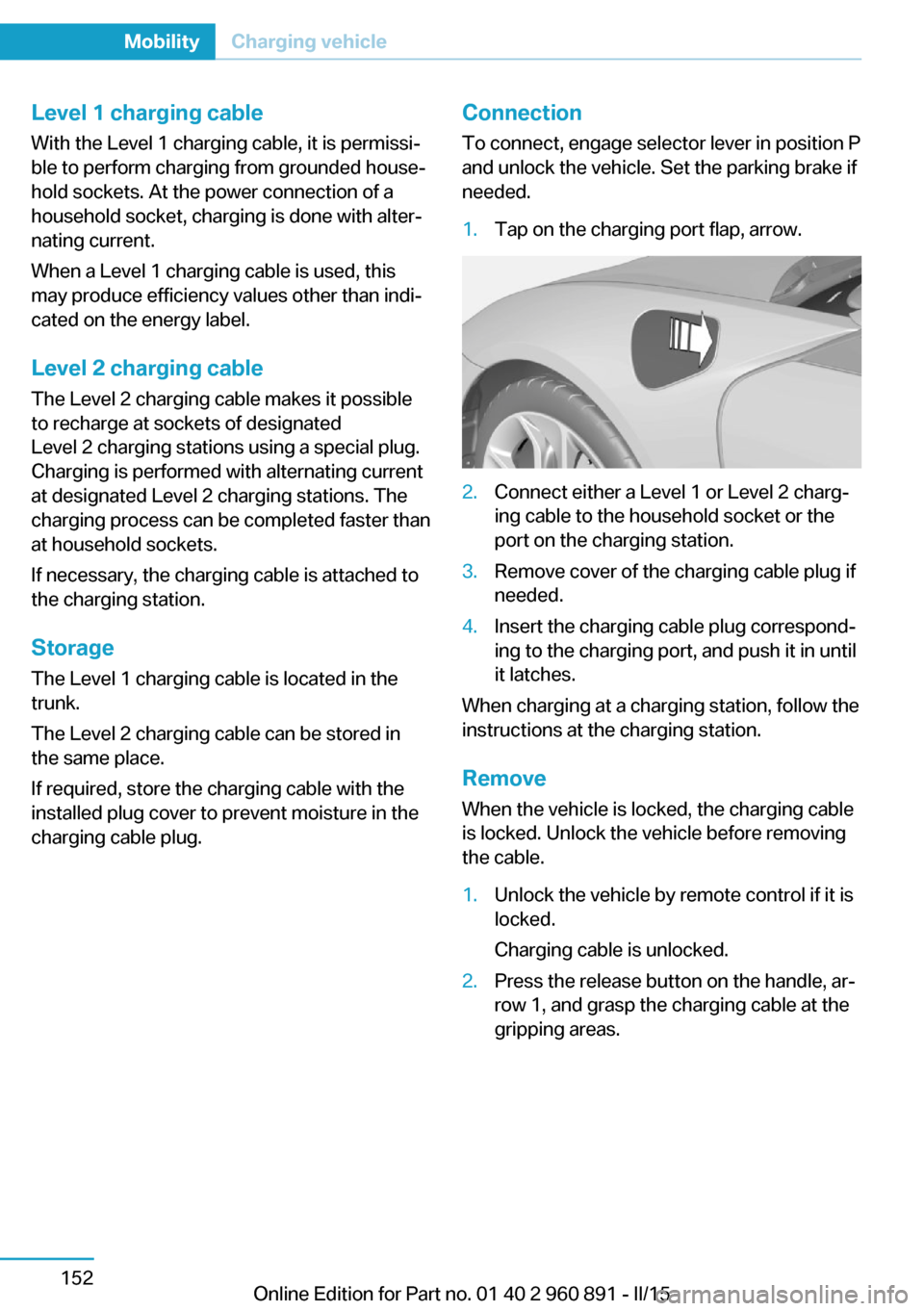
needed.1.Tap on the charging port flap, arrow.2.Connect either a Level 1 or Level 2 charg‐
ing cable to the household socket or the
port on the charging station.3.Remove cover of the charging cable plug if
needed.4.Insert the charging cable plug correspond‐
ing to the charging port, and push it in until
it latches.
When charging at a charging station, follow the
instructions at the charging station.
Remove
When the vehicle is locked, the charging cable
is locked. Unlock the vehicle before removing
the cable.
1.Unlock the vehicle by remote control if it is
locked.
Charging cable is unlocked.2.Press the release button on the handle, ar‐
row 1, and grasp the charging cable at the
gripping areas.Seite 152MobilityCharging vehicle152
Online Edition for Part no. 01 40 2 960 891 - II/15
Page 170 of 224
4.Connect either a Level 1 or Level 2 charg‐
ing cable to the household socket or the
port on the charging station.5.Open charging port flap.6.Connect charging cable to the vehicle, re‐
fer to page 152.
At high temperatures, initially the high-voltage
battery is cooled. The charging process can be
started with a delay.
Display of the charging status
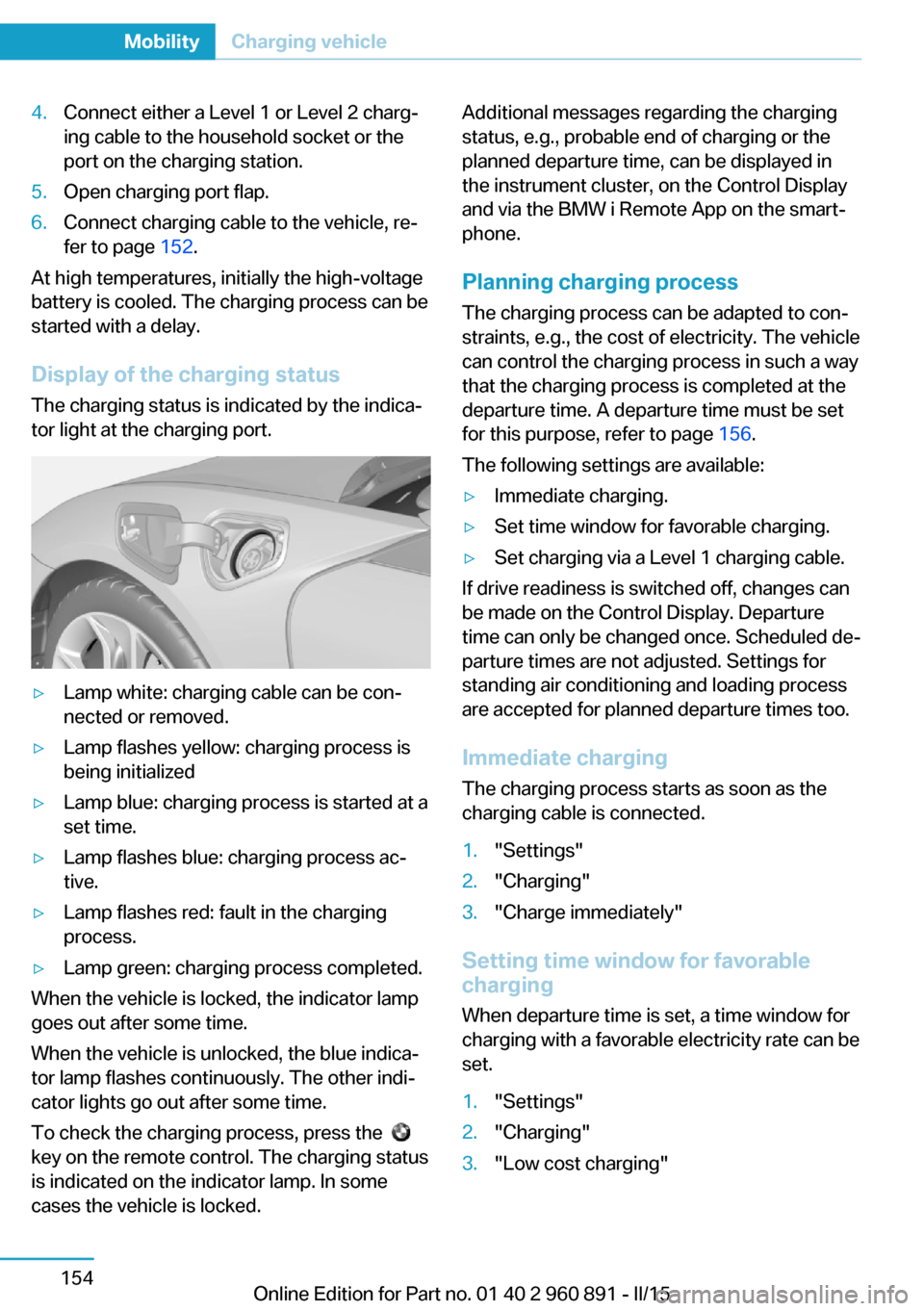
The charging status is indicated by the indica‐
tor light at the charging port.
▷Lamp white: charging cable can be con‐
nected or removed.▷Lamp flashes yellow: charging process is
being initialized▷Lamp blue: charging process is started at a
set time.▷Lamp flashes blue: charging process ac‐
tive.▷Lamp flashes red: fault in the charging
process.▷Lamp green: charging process completed.
When the vehicle is locked, the indicator lamp
goes out after some time.
When the vehicle is unlocked, the blue indica‐
tor lamp flashes continuously. The other indi‐
cator lights go out after some time.
To check the charging process, press the
key on the remote control. The charging status
is indicated on the indicator lamp. In some
cases the vehicle is locked.
Additional messages regarding the charging
status, e.g., probable end of charging or the
planned departure time, can be displayed in
the instrument cluster, on the Control Display
and via the BMW i Remote App on the smart‐
phone.
Planning charging process The charging process can be adapted to con‐
straints, e.g., the cost of electricity. The vehicle
can control the charging process in such a way
that the charging process is completed at the
departure time. A departure time must be set
for this purpose, refer to page 156.
The following settings are available:▷Immediate charging.▷Set time window for favorable charging.▷Set charging via a Level 1 charging cable.
If drive readiness is switched off, changes can
be made on the Control Display. Departure
time can only be changed once. Scheduled de‐
parture times are not adjusted. Settings for
standing air conditioning and loading process
are accepted for planned departure times too.
Immediate chargingThe charging process starts as soon as the
charging cable is connected.
1."Settings"2."Charging"3."Charge immediately"
Setting time window for favorable
charging
When departure time is set, a time window for
charging with a favorable electricity rate can be
set.
1."Settings"2."Charging"3."Low cost charging"Seite 154MobilityCharging vehicle154
Online Edition for Part no. 01 40 2 960 891 - II/15
Page 194 of 224

MaintenanceVehicle features and options
This chapter describes all standard, country-
specific and optional features offered with the
series. It also describes features that are not
necessarily available in your car, e. g., due to
the selected options or country versions. This
also applies to safety-related functions and
systems. The respectively applicable country
provisions must be observed when using the
respective features and systems.
BMW maintenance system The maintenance system indicates required
maintenance measures, and thereby provides
support in maintaining road safety and the op‐
erational reliability of the vehicle.
In some cases scopes and intervals may vary
according to the country-specific version. Re‐
placement work, spare parts, fuels and lubri‐
cants and wear materials are calculated sepa‐
rately. Additional information is available from
the service center.
Note Maintenance and repairs
Have maintenance and repair work per‐
formed only by a service center or a workshop
that works according to BMW specifications
with appropriately trained personnel. Other‐
wise, there is the risk of fatal injury from elec‐
trocution due to the high-voltage system's
high voltage.◀Condition Based Service
CBS
Sensors and special algorithms take into ac‐
count the driving conditions of your vehicle.
Based on this, Condition Based Service recog‐
nizes the maintenance requirements.
The system makes it possible to adapt the
amount of maintenance corresponding to your
user profile.
Detailed information on service requirements,
refer to page 84, can be displayed on the Con‐
trol Display.
Service data in the remote control Information on the required maintenance is
continuously stored in the remote control. Your service center will read out this data and
suggest the right array of service procedures for your vehicle.
Therefore, hand your service specialist the re‐
mote control with which the vehicle was driven
most recently.
Storage periods Storage periods during which the vehicle bat‐
tery was disconnected are not taken into ac‐
count.
If this occurs, have a service center update the
time-dependent maintenance procedures,
such as checking brake fluid and, if needed,
changing the engine oil and the microfilter/
activated-charcoal filter.Seite 178MobilityMaintenance178
Online Edition for Part no. 01 40 2 960 891 - II/15
Page 214 of 224
Everything from A to Z
IndexA ABS, Antilock Brake Sys‐ tem 109
Acceleration Assistant, refer to Launch Control 73
Accessories and parts 7
Acoustic pedestrian protec‐ tion 65
AC quick charging cable, see Level 2 charging cable 152
Activated-charcoal filter 127
Activate drive readiness 63
Adapting to the course of the road, hybrid system 79
Adaptive brake lights, refer to Brake force display 108
Additives, oil 175
Adjustments, seats/head re‐ straints 51
Adjustments, steering wheel 56
Advance climate control, refer to Stationary climate con‐
trol 127
After washing vehicle 188
Airbags 96
Airbags, indicator/warning light 97
Air circulation, refer to Recir‐ culated-air mode 125
Air, dehumidifying, refer to Cooling function 125
Air distribution, manual 126
Air flow, automatic climate control 126
Air pressure, tires 163
Air vents, refer to Ventila‐ tion 127
Alarm system 47
Alarm, unintentional 48 All around the center con‐
sole 16
All around the roofliner 17
All around the steering wheel 14
All-season tires, refer to Win‐ ter tires 168
Alternating-code hand-held transmitter 130
Alternative oil types 176
Ambient light 95
Antifreeze, washer fluid 70
Antilock Brake System, ABS 109
Anti-slip control, refer to DSC 109
Approved axle load 195
Approved engine oils, see Suitable engine oil
types 175
Arrival time 88
Artificial engine noise 65
Assistance for the combus‐ tion engine 65
Assistance when driving off 112
ASSIST, Hybrid system 65
Assist system, refer to Intelli‐ gent Safety 102
AUTO intensity 126
Automatic car wash 187
Automatic climate con‐ trol 124
Automatic Curb Monitor 54
Automatic deactivation, front- seat passenger airbags 98
Automatic deactivation of the high-voltage system 34
Automatic headlight con‐ trol 93
Automatic locking 47 Automatic recirculated-air
control 125
Automatic transmission, see Steptronic Sport transmis‐
sion 70
AUTO program, automatic cli‐ mate control 126
AUTO program, intensity 126
Average fuel consumption 87
Average speed 88
Axle loads, weights 195
B Backup charging 156
Band-aids, refer to First aid kit 184
Battery, 12 volt 181
Battery replacement, vehicle battery 181
Battery replacement, vehicle remote control 39
Battery state indicator 77
Battery, vehicle 181
Belts, safety belts 53
BMW Assist 6
BMW eDRIVE 31
BMW Homepage 6
BMW i Driver’s Guide App 6
BMW Internet page 6
BMW maintenance sys‐ tem 178
Body work, see Working on the vehicle 34
Brake assistant 109
Brake discs, break-in 138
Brake force display 108
Brake lights, adaptive 108
Brake lights, brake force dis‐ play 108
Brake pads, break-in 138 Seite 198ReferenceEverything from A to Z198
Online Edition for Part no. 01 40 2 960 891 - II/15