2015 BMW I8 steering
[x] Cancel search: steeringPage 90 of 224
rupted driving with the combustion engine of
at least 6 miles/10 km.
To start with Launch Control do not steer the
steering wheel.
Start with launch controlWith the combustion engine running:1. Press button.
TRACTION is displayed in the instrument
cluster and the indicator lamp for DSC OFF
lights up.2.Engage selector lever position S.3.With the left foot, forcefully press down on
the brake.4.Press and hold down the accelerator pedal
beyond the resistance point at the full
throttle position.
A flag symbol is displayed in the instru‐
ment cluster.5.The starting engine speed adjusts. Within
3 seconds, release the brake.
Before using Launch Control, allow the trans‐
mission to cool down for approx. 5 minutes.
Seite 74ControlsDriving74
Online Edition for Part no. 01 40 2 960 891 - II/15
Page 96 of 224
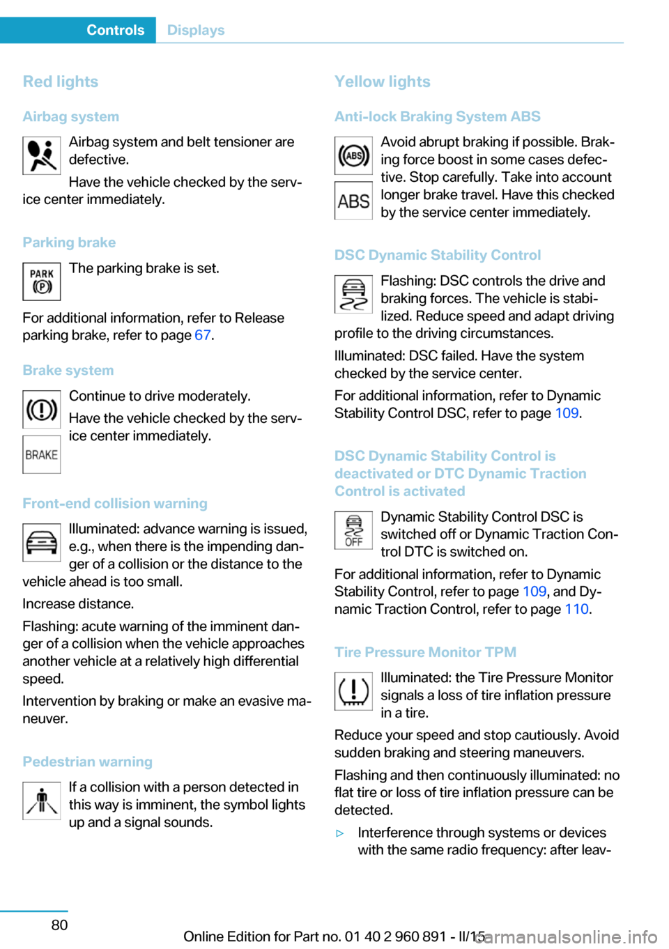
Red lightsAirbag system Airbag system and belt tensioner are
defective.
Have the vehicle checked by the serv‐
ice center immediately.
Parking brake The parking brake is set.
For additional information, refer to Release
parking brake, refer to page 67.
Brake system Continue to drive moderately.
Have the vehicle checked by the serv‐
ice center immediately.
Front-end collision warning Illuminated: advance warning is issued,
e.g., when there is the impending dan‐
ger of a collision or the distance to the
vehicle ahead is too small.
Increase distance.
Flashing: acute warning of the imminent dan‐
ger of a collision when the vehicle approaches
another vehicle at a relatively high differential
speed.
Intervention by braking or make an evasive ma‐
neuver.
Pedestrian warning If a collision with a person detected in
this way is imminent, the symbol lights
up and a signal sounds.Yellow lights
Anti-lock Braking System ABS Avoid abrupt braking if possible. Brak‐
ing force boost in some cases defec‐
tive. Stop carefully. Take into account
longer brake travel. Have this checked
by the service center immediately.
DSC Dynamic Stability Control Flashing: DSC controls the drive and
braking forces. The vehicle is stabi‐
lized. Reduce speed and adapt driving
profile to the driving circumstances.
Illuminated: DSC failed. Have the system
checked by the service center.
For additional information, refer to Dynamic
Stability Control DSC, refer to page 109.
DSC Dynamic Stability Control is
deactivated or DTC Dynamic Traction
Control is activated
Dynamic Stability Control DSC is
switched off or Dynamic Traction Con‐
trol DTC is switched on.
For additional information, refer to Dynamic
Stability Control, refer to page 109, and Dy‐
namic Traction Control, refer to page 110.
Tire Pressure Monitor TPM Illuminated: the Tire Pressure Monitor
signals a loss of tire inflation pressure
in a tire.
Reduce your speed and stop cautiously. Avoid
sudden braking and steering maneuvers.
Flashing and then continuously illuminated: no
flat tire or loss of tire inflation pressure can be
detected.▷Interference through systems or devices
with the same radio frequency: after leav‐Seite 80ControlsDisplays80
Online Edition for Part no. 01 40 2 960 891 - II/15
Page 97 of 224

ing the area of the interference, the system
automatically becomes active again.▷TPM could not conclude the reset: perform
the reset of the system again.▷A wheel without TPM electronics is fitted:
have the service center check it if needed.▷Malfunction: have the system checked by
your service center.
For more information, see Tire Pressure Moni‐
tor, refer to page 99.
Steering system Steering system in some cases defec‐
tive.
Have the steering system checked by
the service center.
Engine functions Have the vehicle checked by the serv‐ice center.
For additional information, refer to On-
board Diagnostics socket, refer to page 179.
Acoustic pedestrian protection inactive Acoustic pedestrian protection possi‐
bly defective.
Have the system checked by the serv‐
ice center.
Green lights Turn signal Turn signal on.
Unusually rapid flashing of the indicator
lamp indicates that a turn signal bulb
has failed.
For additional information, refer to Turn signal, refer to page 67.
Parking lights, headlight control
Parking lights or headlights are acti‐
vated.
For additional information, refer to
Parking lights/low beams, headlight control, re‐
fer to page 92.
High-beam Assistant High-beam Assistant is switched on.
High beams are activated and off auto‐
matically as a function of the traffic sit‐
uation.
For additional information, refer to High-beam
Assistant, refer to page 94.
Cruise control The system is switched on. It maintains
the speed that was set using the con‐
trol elements on the steering wheel.
Blue lights
High beams High beams are activated.
For additional information, refer to High
beams, refer to page 68.
General lamps
Check Control At least one Check Control message is
displayed or is stored. The symbol is
shown in the display of the instrument
cluster.
Text messagesText messages in combination with a symbol
in the instrument cluster explain a Check Con‐ trol message and the meaning of the indicator
and warning lights.Seite 81DisplaysControls81
Online Edition for Part no. 01 40 2 960 891 - II/15
Page 102 of 224
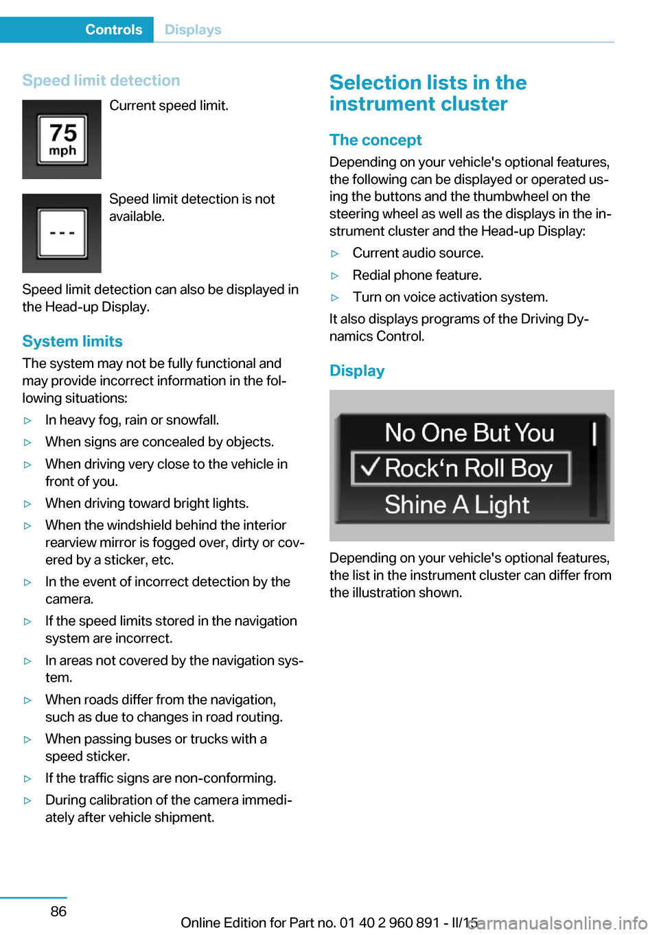
Speed limit detectionCurrent speed limit.
Speed limit detection is not
available.
Speed limit detection can also be displayed in
the Head-up Display.
System limits
The system may not be fully functional and
may provide incorrect information in the fol‐
lowing situations:▷In heavy fog, rain or snowfall.▷When signs are concealed by objects.▷When driving very close to the vehicle in
front of you.▷When driving toward bright lights.▷When the windshield behind the interior
rearview mirror is fogged over, dirty or cov‐
ered by a sticker, etc.▷In the event of incorrect detection by the
camera.▷If the speed limits stored in the navigation
system are incorrect.▷In areas not covered by the navigation sys‐
tem.▷When roads differ from the navigation,
such as due to changes in road routing.▷When passing buses or trucks with a
speed sticker.▷If the traffic signs are non-conforming.▷During calibration of the camera immedi‐
ately after vehicle shipment.Selection lists in the
instrument cluster
The concept Depending on your vehicle's optional features,
the following can be displayed or operated us‐
ing the buttons and the thumbwheel on the
steering wheel as well as the displays in the in‐
strument cluster and the Head-up Display:▷Current audio source.▷Redial phone feature.▷Turn on voice activation system.
It also displays programs of the Driving Dy‐
namics Control.
Display
Depending on your vehicle's optional features,
the list in the instrument cluster can differ from
the illustration shown.
Seite 86ControlsDisplays86
Online Edition for Part no. 01 40 2 960 891 - II/15
Page 103 of 224
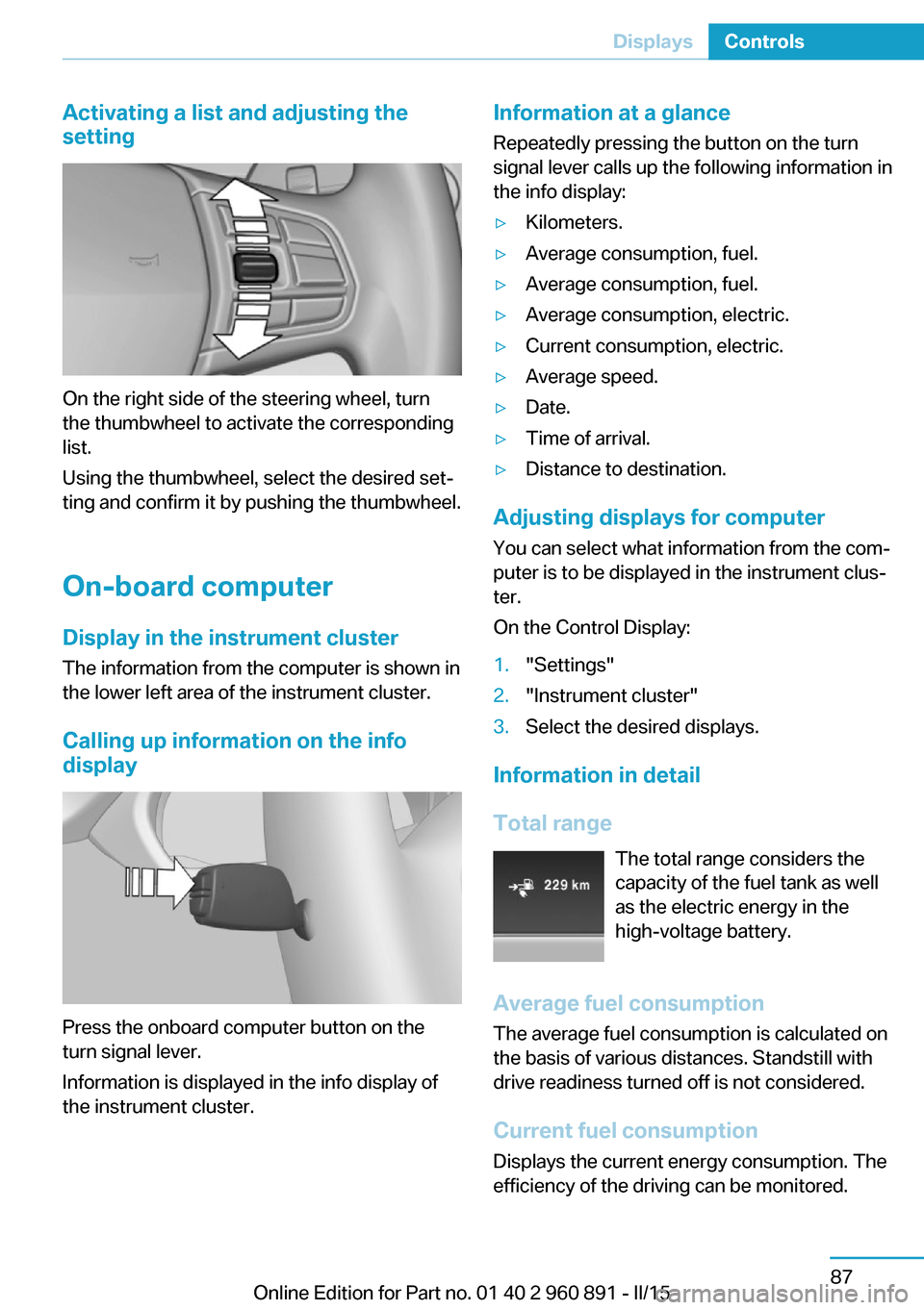
Activating a list and adjusting the
setting
On the right side of the steering wheel, turn
the thumbwheel to activate the corresponding
list.
Using the thumbwheel, select the desired set‐
ting and confirm it by pushing the thumbwheel.
On-board computer
Display in the instrument cluster The information from the computer is shown in
the lower left area of the instrument cluster.
Calling up information on the info display
Press the onboard computer button on the
turn signal lever.
Information is displayed in the info display of
the instrument cluster.
Information at a glance
Repeatedly pressing the button on the turn
signal lever calls up the following information in
the info display:▷Kilometers.▷Average consumption, fuel.▷Average consumption, fuel.▷Average consumption, electric.▷Current consumption, electric.▷Average speed.▷Date.▷Time of arrival.▷Distance to destination.
Adjusting displays for computer
You can select what information from the com‐
puter is to be displayed in the instrument clus‐
ter.
On the Control Display:
1."Settings"2."Instrument cluster"3.Select the desired displays.
Information in detail
Total range The total range considers the
capacity of the fuel tank as well
as the electric energy in the
high-voltage battery.
Average fuel consumption
The average fuel consumption is calculated on
the basis of various distances. Standstill with
drive readiness turned off is not considered.
Current fuel consumption Displays the current energy consumption. The
efficiency of the driving can be monitored.
Seite 87DisplaysControls87
Online Edition for Part no. 01 40 2 960 891 - II/15
Page 113 of 224
Knee airbagThe knee airbag supports the legs in a frontal
impact.
Protective action
Airbags are not triggered in every impact situa‐
tion, e.g., in less severe accidents or rear-end
collisions.
Information on how to ensure the optimal
protective effect of the airbags▷Keep at a distance from the airbags.▷Always grasp the steering wheel on the
steering wheel rim, holding your hands at
the 3 o'clock and 9 o'clock positions, to
keep the risk of injury to your hands or
arms as low as possible when the airbag is
triggered.▷There should be no person, animals, or ob‐
jects between an airbag and a person.▷Do not use the cover of the front airbag on
the front passenger side as a storage area.▷Dashboard and windshield on the front
passenger side must stay clear - do not at‐
tach adhesive labels or coverings and do
not attach brackets or cables, e. g., for GPS
devices or' mobile phones.▷Make sure that the front passenger is sit‐
ting correctly, i.e., keeps his or her feet and
legs in the footwell; otherwise, leg injuries
might occur when front airbag is activated.▷Do not place slip covers, seat cushions or
other objects on the front passenger seat
that are not approved specifically for seats
with integrated side airbags.▷Do not hang pieces of clothing, such as
jackets, over the backrests.▷Make sure that occupants keep their heads
away from the side airbag and do not rest
against the head airbag; otherwise, injuries
might occur when airbag is activated.▷Do not remove the airbag system.▷Do not remove the steering wheel.▷Do not apply adhesive materials to the air‐
bag cover panels, do not cover them or
modify them in any way.▷Never modify either the individual compo‐
nents or the wiring in the airbag system.
This also applies to steering wheel covers,
the dashboard, the seats, the roof pillars
and the sides of the roofliner.◀
Even when you follow all instructions very
closely, injury from contact with the airbags
cannot be ruled out in certain situations.
The ignition and inflation noise may lead to
short-term and, in most cases, temporary
hearing impairment in sensitive individuals.
Malfunction, deactivation and after de‐
ploying the airbags
Do not touch the individual components imme‐
diately after the system has been triggered;
otherwise, you may risk burns.
Only have the airbags checked, repaired or dis‐
mantled and the airbag generator scrapped by
the service center or an authorized repair shop
for handling explosives.
Non-professional attempts to service the sys‐
tem could lead to failure in an emergency or
unintentional activation of the airbag - both
may lead to injury.◀
Warnings and information on the airbags are also found on the sun visors.
Functional readiness of the airbag
system
With operating readiness turned on
warning light in the instrument cluster
lights up briefly indicating airbag sys‐
tem and belt tension are functional.
Airbag system malfunctioning
▷Warning lamp does not come on when op‐
erating readiness is turned on.▷The warning lamp lights up continuously.Seite 97SafetyControls97
Online Edition for Part no. 01 40 2 960 891 - II/15
Page 116 of 224
Status control displayTire and system status are indicated by the
color of the wheels and a text message on the
Control Display.
All wheels green System is active and will issue a warning rela‐
tive to the tire inflation pressures stored during
the last reset.
One wheel is yellow A flat tire or major drop in inflation pressure in
the indicated tire.
All wheels are yellow A flat tire or major drop in inflation pressure in
several tires.
Wheels, gray The system cannot detect a flat tire. Reasons
for this may be:▷The system is being reset.▷Malfunction.
Status information
The status control display additionally shows
the current tire inflation pressures and, de‐
pending on the model, tire temperatures. It
shows the actual values read; they may vary depending on driving style or weather condi‐
tions.
Carry out reset Reset the system after each adjustment of the
tire inflation pressure and after every tire or
wheel change.
On the Control Display and on the vehicle:
1."Vehicle info"2."Vehicle status"3. "Perform reset"4.Switch on drive readiness – do not drive
off.5.Reset tire inflation pressure:"Perform
reset".6.Drive away.
The tires are shown in gray and the status is
displayed.
After driving faster than 19 mph/30 km/h for a
short period, the set tire inflation pressures are
accepted as reference values. The reset is
completed automatically while driving.
The progress of the reset is displayed.
After a successfully completed Reset, the
wheels on the Control Display are shown in
green and "Tire Pressure Monitor (TPM)
active" is displayed.
You may interrupt this trip at any time. When
you continue the reset resumes automatically.
Low tire pressure message The yellow warning lamp lights up. A
Check Control message is displayed.
▷There is a flat tire or a major loss in
tire inflation pressure.▷No reset was performed for the system.
The system therefore issues a warning
based on the tire inflation pressures before
the last reset.
Reduce your speed and stop cautiously. Avoid
sudden braking and steering maneuvers. Do
not continue driving, and contact the service
center.
If a Mobility System is not available, contact
the service center.
A low tire inflation pressure might turn on DSC
Dynamic Stability Control.
Required tire inflation pressure check
message
A Check Control message is displayed in the
following situations
▷The system has detected a wheel change,
but no reset was done.Seite 100ControlsSafety100
Online Edition for Part no. 01 40 2 960 891 - II/15
Page 121 of 224
Acute warnings can also be triggered without
previous prewarning.
Braking intervention The warning prompts the driver himself/herself
to react. During a warning, the maximum brak‐
ing force is used. Premise for the brake boos‐
ter is sufficiently quick and hard stepping on
the brake pedal. The system can assist with
some braking intervention if there is risk of a
collision. At low speeds vehicles may thus
come to a complete stop.
The braking intervention is executed only if
DSC Dynamic Stability Control is switched on.
The braking intervention can be interrupted by
stepping on the accelerator pedal or by ac‐
tively moving the steering wheel.
Object detection can be restricted. Limitations
of the detection range and functional restric‐
tions are to be considered.
System limits
Detection range
The system's detection potential is limited.
Thus a warning might not be issued or be is‐
sued late.
E. g. the following situations may not be de‐
tected:▷Slow moving vehicles when you approach
them at high speed.▷Vehicles that suddenly swerve in front of
you, or sharply decelerating vehicles.▷Vehicles with an unusual rear appearance.▷Two-wheeled vehicles ahead of you.
Functional limitations
The system may not be fully functional in the
following situations:
▷In heavy fog, rain, sprayed water or snow‐
fall.▷In tight curves.▷If the driving stability control systems are
deactivated, e.g. DSC OFF.▷If the field of view of the camera in the mir‐
ror is dirty or obscured.▷Up to 10 seconds after drive readiness is
established.▷During calibration of the camera immedi‐
ately after vehicle shipment.▷If there is constant blinding effects be‐
cause of oncoming light, e. g., from the sun
low in the sky.
Warning sensitivity
The more sensitive the warning settings are,
e.g. the warning time, the more warnings are
displayed. However, there may also be an ex‐
cess of false warnings.
Pedestrian warning with city
braking function
The concept The ystem can help prevent accidents with pe‐
destrians.
The system issues a warning in the city driving
speed area if there is imminent danger of a col‐
lision with pedestrians and includes a braking
function.
The camera in the area of the rearview mirror
controls the system.
General information In daylight the system warns of possible colli‐
sions with pedestrians at speeds from about
6 mph/10 km/h to about 35 mph/60 km/h
shortly before a collision the system supports
you with a braking intervention.
Under those circumstances it reacts to people
who are within the detection range of the sys‐
tem.
Seite 105SafetyControls105
Online Edition for Part no. 01 40 2 960 891 - II/15