2015 BMW 640I GRAN COUPE interior light
[x] Cancel search: interior lightPage 119 of 255
At a glance
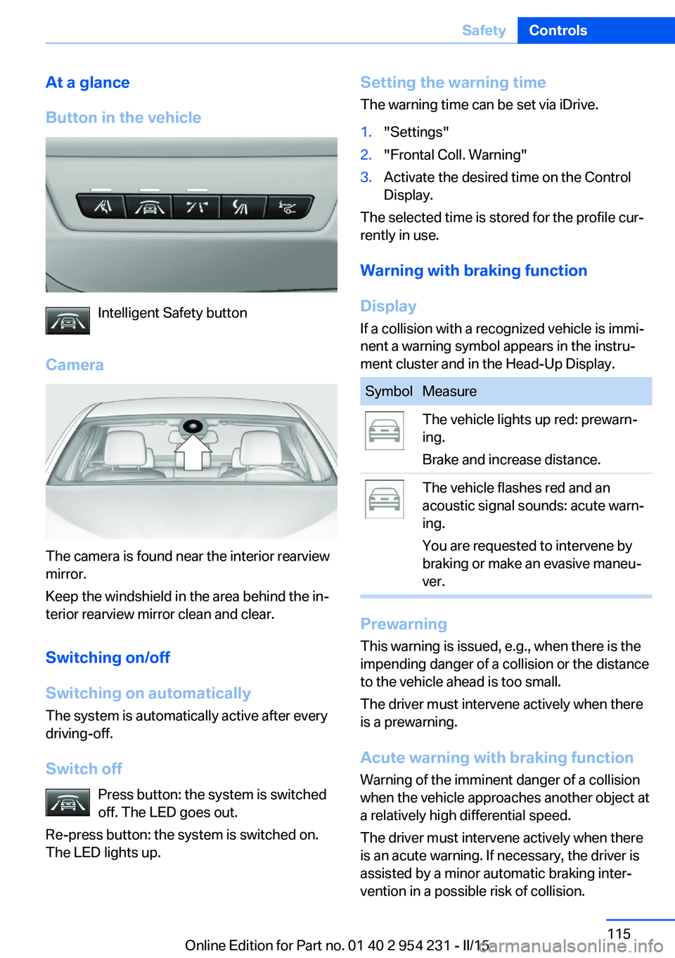
Button in the vehicle
Intelligent Safety button
Camera
The camera is found near the interior rearview
mirror.
Keep the windshield in the area behind the in‐
terior rearview mirror clean and clear.
Switching on/off
Switching on automatically The system is automatically active after every
driving-off.
Switch off Press button: the system is switched
off. The LED goes out.
Re-press button: the system is switched on.
The LED lights up.
Setting the warning time
The warning time can be set via iDrive.1."Settings"2."Frontal Coll. Warning"3.Activate the desired time on the Control
Display.
The selected time is stored for the profile cur‐
rently in use.
Warning with braking function
Display If a collision with a recognized vehicle is immi‐
nent a warning symbol appears in the instru‐
ment cluster and in the Head-Up Display.
SymbolMeasureThe vehicle lights up red: prewarn‐
ing.
Brake and increase distance.The vehicle flashes red and an
acoustic signal sounds: acute warn‐
ing.
You are requested to intervene by
braking or make an evasive maneu‐
ver.
Prewarning
This warning is issued, e.g., when there is the
impending danger of a collision or the distance
to the vehicle ahead is too small.
The driver must intervene actively when there
is a prewarning.
Acute warning with braking function
Warning of the imminent danger of a collision
when the vehicle approaches another object at
a relatively high differential speed.
The driver must intervene actively when there
is an acute warning. If necessary, the driver is
assisted by a minor automatic braking inter‐
vention in a possible risk of collision.
Seite 115SafetyControls115
Online Edition for Part no. 01 40 2 954 231 - II/15
Page 122 of 255
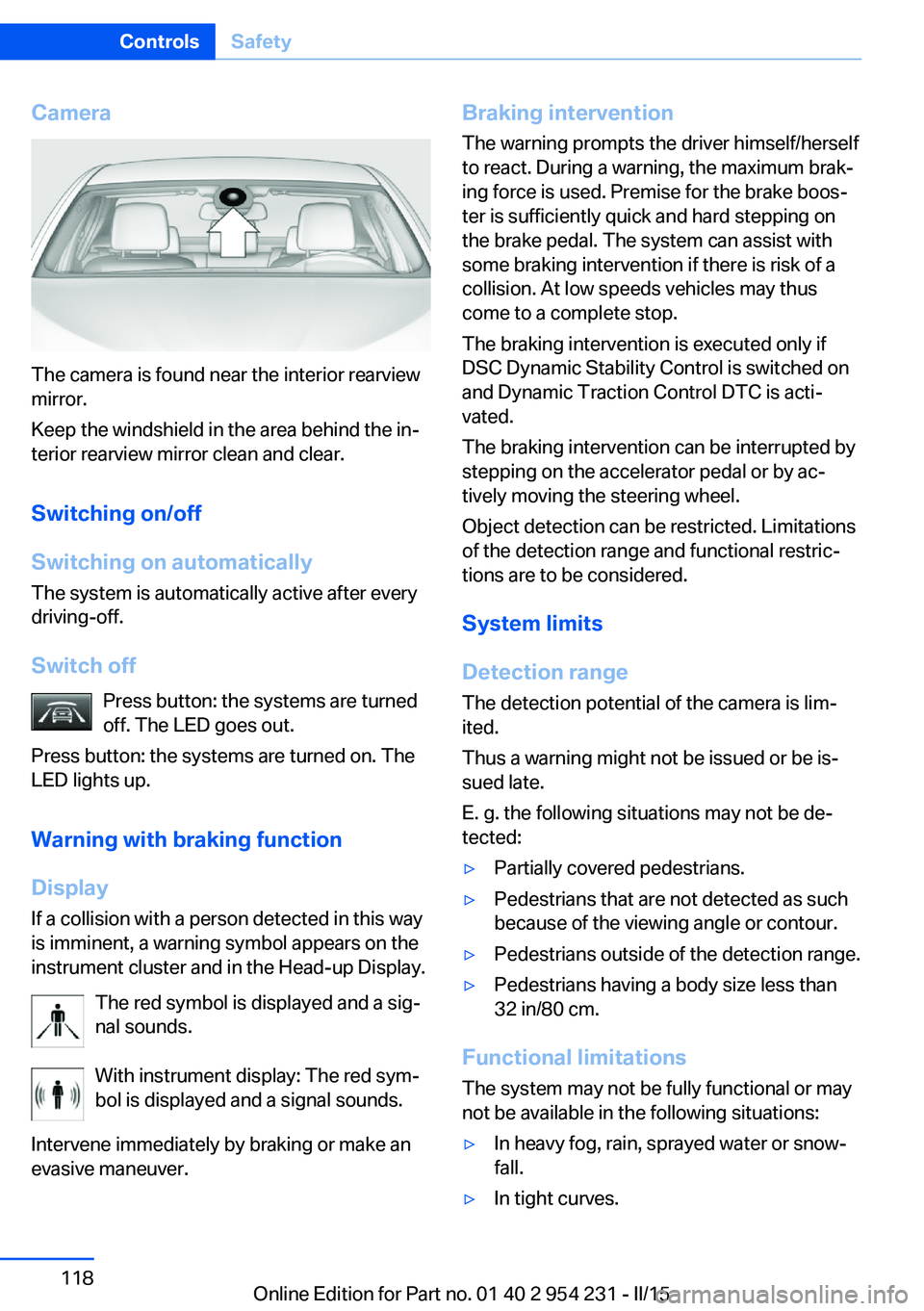
Camera
The camera is found near the interior rearview
mirror.
Keep the windshield in the area behind the in‐
terior rearview mirror clean and clear.
Switching on/off
Switching on automatically The system is automatically active after every
driving-off.
Switch off Press button: the systems are turned
off. The LED goes out.
Press button: the systems are turned on. The
LED lights up.
Warning with braking function
Display
If a collision with a person detected in this way
is imminent, a warning symbol appears on the
instrument cluster and in the Head-up Display.
The red symbol is displayed and a sig‐
nal sounds.
With instrument display: The red sym‐
bol is displayed and a signal sounds.
Intervene immediately by braking or make an
evasive maneuver.
Braking intervention
The warning prompts the driver himself/herself
to react. During a warning, the maximum brak‐
ing force is used. Premise for the brake boos‐
ter is sufficiently quick and hard stepping on
the brake pedal. The system can assist with
some braking intervention if there is risk of a
collision. At low speeds vehicles may thus
come to a complete stop.
The braking intervention is executed only if
DSC Dynamic Stability Control is switched on
and Dynamic Traction Control DTC is acti‐
vated.
The braking intervention can be interrupted by
stepping on the accelerator pedal or by ac‐
tively moving the steering wheel.
Object detection can be restricted. Limitations
of the detection range and functional restric‐
tions are to be considered.
System limits
Detection range
The detection potential of the camera is lim‐
ited.
Thus a warning might not be issued or be is‐
sued late.
E. g. the following situations may not be de‐
tected:▷Partially covered pedestrians.▷Pedestrians that are not detected as such
because of the viewing angle or contour.▷Pedestrians outside of the detection range.▷Pedestrians having a body size less than
32 in/80 cm.
Functional limitations
The system may not be fully functional or may
not be available in the following situations:
▷In heavy fog, rain, sprayed water or snow‐
fall.▷In tight curves.Seite 118ControlsSafety118
Online Edition for Part no. 01 40 2 954 231 - II/15
Page 127 of 255
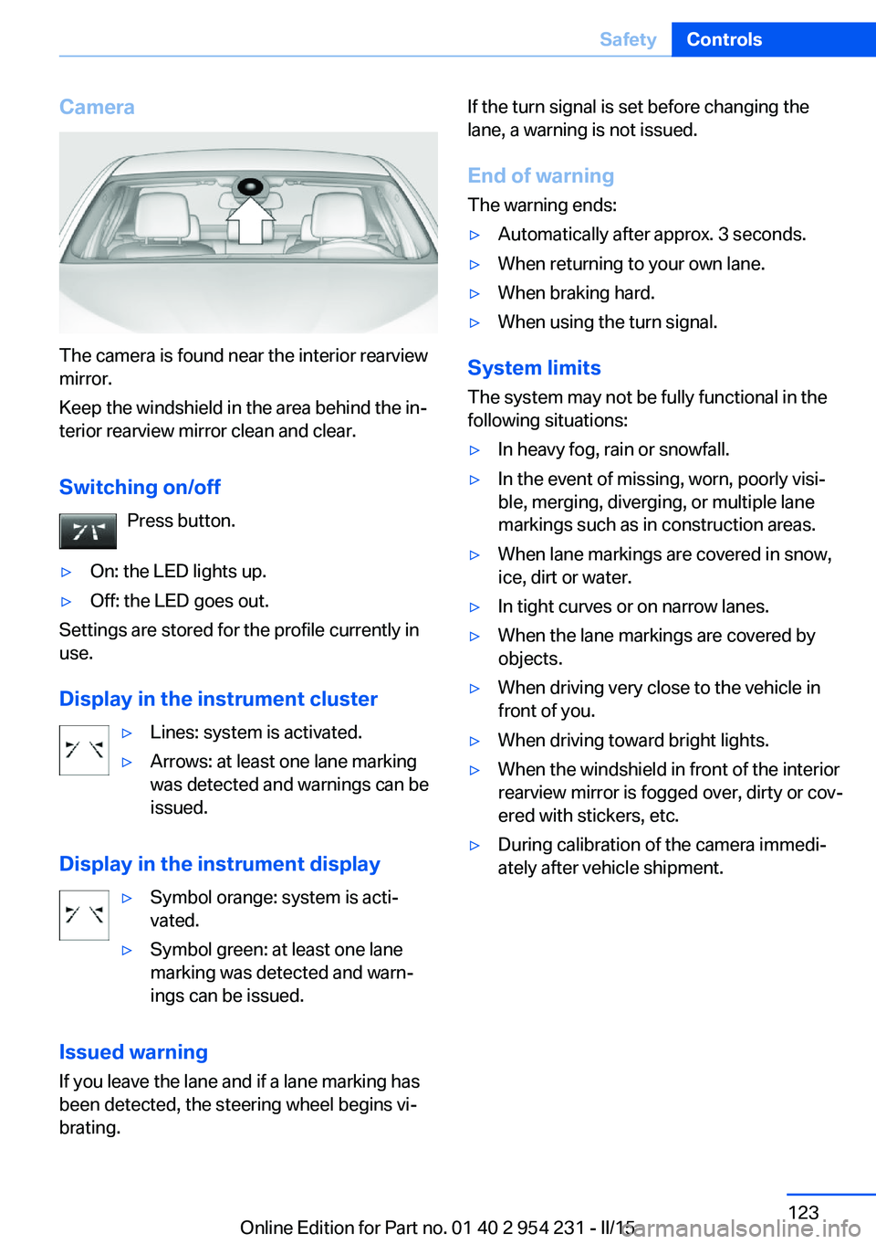
Camera
The camera is found near the interior rearview
mirror.
Keep the windshield in the area behind the in‐
terior rearview mirror clean and clear.
Switching on/off Press button.
▷On: the LED lights up.▷Off: the LED goes out.
Settings are stored for the profile currently in
use.
Display in the instrument cluster
▷Lines: system is activated.▷Arrows: at least one lane marking
was detected and warnings can be
issued.
Display in the instrument display
▷Symbol orange: system is acti‐
vated.▷Symbol green: at least one lane
marking was detected and warn‐
ings can be issued.
Issued warning
If you leave the lane and if a lane marking has
been detected, the steering wheel begins vi‐
brating.
If the turn signal is set before changing the
lane, a warning is not issued.
End of warning The warning ends:▷Automatically after approx. 3 seconds.▷When returning to your own lane.▷When braking hard.▷When using the turn signal.
System limits
The system may not be fully functional in the
following situations:
▷In heavy fog, rain or snowfall.▷In the event of missing, worn, poorly visi‐
ble, merging, diverging, or multiple lane
markings such as in construction areas.▷When lane markings are covered in snow,
ice, dirt or water.▷In tight curves or on narrow lanes.▷When the lane markings are covered by
objects.▷When driving very close to the vehicle in
front of you.▷When driving toward bright lights.▷When the windshield in front of the interior
rearview mirror is fogged over, dirty or cov‐
ered with stickers, etc.▷During calibration of the camera immedi‐
ately after vehicle shipment.Seite 123SafetyControls123
Online Edition for Part no. 01 40 2 954 231 - II/15
Page 169 of 255
Interior equipmentVehicle features and optionsThis chapter describes all standard, country-
specific and optional features offered with the
series. It also describes features that are not
necessarily available in your car, e. g., due to
the selected options or country versions. This
also applies to safety-related functions and
systems. The respectively applicable country
provisions must be observed when using the
respective features and systems.
Universal Integrated Remote Control
The concept The universal garage door opener can operate
up to 3 functions of remote-controlled sys‐
tems such as garage door drives or lighting
systems. The universal garage door opener re‐
places up to 3 different hand-held transmitters.
To operate the remote control, the buttons on
the interior rearview mirror must be program‐
med with the desired functions. The hand-held
transmitter for the particular system is required
in order to program the remote control.
During programming
During programming and before activat‐
ing a device using the universal garage door
opener, ensure that there are no people, ani‐
mals or objects in the area of the remote-con‐
trolled device; otherwise, there is a risk of in‐
jury or damage.
Also follow the safety instructions of the hand-
held transmitter.◀
Before selling the vehicle, delete the stored
functions for the sake of security.Compatibility
If this symbol is printed on the packag‐
ing or in the instructions of the system
to be controlled, the system is gener‐
ally compatible with the universal garage door opener.
If you have any questions, please contact:▷Your service center.▷www.homelink.com on the Internet.
HomeLink is a registered trademark of Gentex
Corporation.
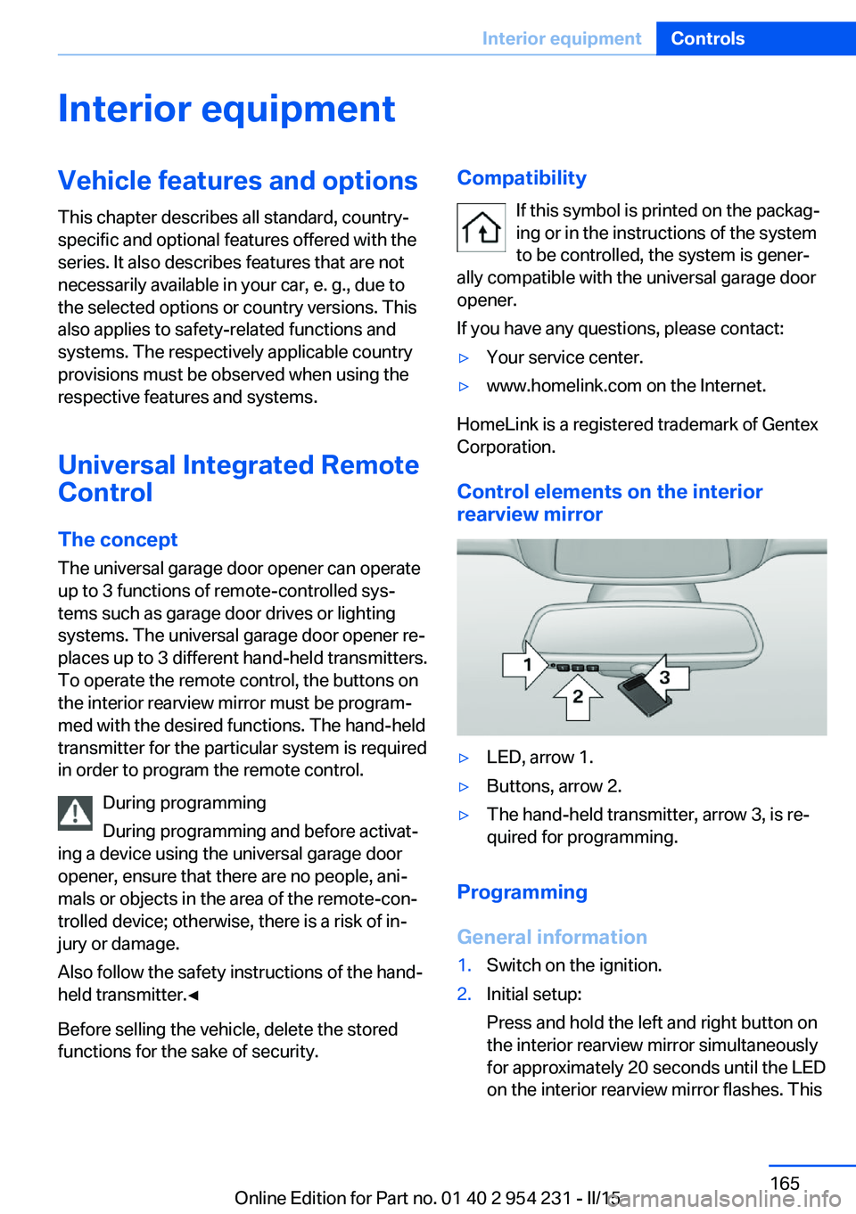
Control elements on the interior
rearview mirror
▷LED, arrow 1.▷Buttons, arrow 2.▷The hand-held transmitter, arrow 3, is re‐
quired for programming.
Programming
General information
1.Switch on the ignition.2.Initial setup:
Press and hold the left and right button on
the interior rearview mirror simultaneously
for approximately 20 seconds until the LED
on the interior rearview mirror flashes. ThisSeite 165Interior equipmentControls165
Online Edition for Part no. 01 40 2 954 231 - II/15
Page 171 of 255
4.Likewise, press and hold the button of the
desired function on the hand-held trans‐
mitter.5.Release both buttons as soon as the inte‐
rior rearview mirror LED flashes more rap‐
idly. The LED flashing faster indicates that
the button on the interior rearview mirror
has been programmed. The system can
then be controlled by the button on the in‐
terior rearview mirror.
If the LED does not flash faster after at
least 60 seconds, change the distance and
repeat the step. Several more attempts at
different distances may be necessary. Wait
at least 15 seconds between attempts.
Canada: if programming with the hand-
held transmitter was interrupted, hold
down the interior rearview mirror button
and repeatedly press and release the
hand-held transmitter button for 2 sec‐
onds.
Controls
Before operation
Before operating a system using the uni‐
versal garage door opener, ensure that there are no people, animals, or objects within the
range of movement of the remote-controlled
system; otherwise, there is a risk of injury or
damage.
Also follow the safety instructions of the hand-
held transmitter.◀
The system, such as the garage door, can be
operated using the button on the interior rear‐
view mirror while the engine is running or when
the ignition is started. To do this, hold down
the button within receiving range of the system
until the function is activated. The interior rear‐ view mirror LED stays lit while the wireless sig‐
nal is being transmitted.
Deleting stored functions Press and hold the left and right button on the
interior rearview mirror simultaneously for ap‐
proximately 20 seconds until the LED flashes
rapidly. All stored functions are deleted. The
functions cannot be deleted individually.
Sun visor Glare shieldFold the sun visor down or up.
Vanity mirror A vanity mirror is located in the sun visor be‐
hind a cover. When the cover is opened, the
mirror lighting switches on.
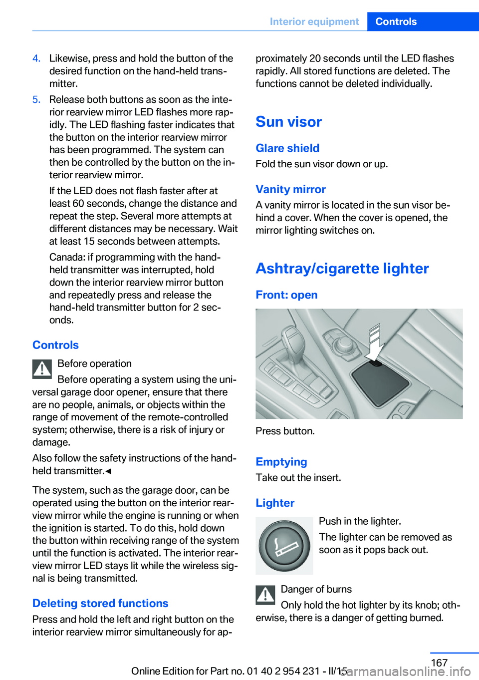
Ashtray/cigarette lighterFront: open
Press button.
Emptying Take out the insert.
Lighter Push in the lighter.
The lighter can be removed as
soon as it pops back out.
Danger of burns
Only hold the hot lighter by its knob; oth‐
erwise, there is a danger of getting burned.
Seite 167Interior equipmentControls167
Online Edition for Part no. 01 40 2 954 231 - II/15
Page 172 of 255
Switch off the ignition and take the remote
control with you when leaving the vehicle so
that children cannot use the lighter and burn
themselves.◀
Replace the cover after use
Reinsert the lighter or socket cover after
use, otherwise objects may get into the lighter
socket or fixture and cause a short circuit.◀
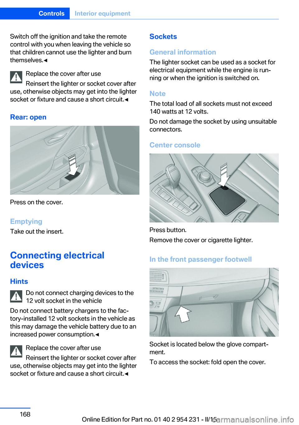
Rear: open
Press on the cover.
Emptying Take out the insert.
Connecting electrical devices
Hints Do not connect charging devices to the
12 volt socket in the vehicle
Do not connect battery chargers to the fac‐
tory-installed 12 volt sockets in the vehicle as
this may damage the vehicle battery due to an
increased power consumption.◀
Replace the cover after use
Reinsert the lighter or socket cover after
use, otherwise objects may get into the lighter
socket or fixture and cause a short circuit.◀
Sockets
General information
The lighter socket can be used as a socket for
electrical equipment while the engine is run‐
ning or when the ignition is switched on.
NoteThe total load of all sockets must not exceed
140 watts at 12 volts.
Do not damage the socket by using unsuitable
connectors.
Center console
Press button.
Remove the cover or cigarette lighter.
In the front passenger footwell
Socket is located below the glove compart‐
ment.
To access the socket: fold open the cover.
Seite 168ControlsInterior equipment168
Online Edition for Part no. 01 40 2 954 231 - II/15
Page 174 of 255
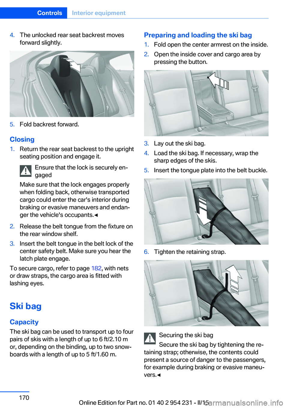
4.The unlocked rear seat backrest moves
forward slightly.5.Fold backrest forward.
Closing
1.Return the rear seat backrest to the upright
seating position and engage it.
Ensure that the lock is securely en‐
gaged
Make sure that the lock engages properly
when folding back, otherwise transported
cargo could enter the car's interior during
braking or evasive maneuvers and endan‐
ger the vehicle's occupants.◀2.Release the belt tongue from the fixture on
the rear window shelf.3.Insert the belt tongue in the belt lock of the
center safety belt. Make sure you hear the
latch plate engage.
To secure cargo, refer to page 182, with nets
or draw straps, the cargo area is fitted with
lashing eyes.
Ski bag
Capacity
The ski bag can be used to transport up to four
pairs of skis with a length of up to 6 ft/2.10 m
or, depending on the binding, up to two snow‐
boards with a length of up to 5 ft/1.60 m.
Preparing and loading the ski bag1.Fold open the center armrest on the inside.2.Open the inside cover and cargo area by
pressing the button.3.Lay out the ski bag.4.Load the ski bag. If necessary, wrap the
sharp edges of the skis.5.Insert the tongue plate into the belt buckle.6.Tighten the retaining strap.
Securing the ski bag
Secure the ski bag by tightening the re‐
taining strap; otherwise, the contents could
present a source of danger to the passengers,
for example during braking or evasive maneu‐
vers.◀
Seite 170ControlsInterior equipment170
Online Edition for Part no. 01 40 2 954 231 - II/15
Page 176 of 255
Storage compartmentsVehicle features and optionsThis chapter describes all standard, country-
specific and optional features offered with the
series. It also describes features that are not
necessarily available in your car, e. g., due to
the selected options or country versions. This
also applies to safety-related functions and
systems. The respectively applicable country
provisions must be observed when using the
respective features and systems.
Hints No loose objects in the car's interior
Do not stow any objects in the car's inte‐
rior without securing them; otherwise, they
may present a danger to occupants e.g., during
braking and evasive maneuvers.◀
Do not place anti-slip mats on the dash‐
board
Do not place anti-slip mats on the dashboard.
The mat materials could damage the dash‐
board.◀
Storage compartments The following storage compartments are avail‐
able in the vehicle interior:▷Glove compartment on the front passenger
side, refer to page 172.▷Storage compartment in the front center
armrest, refer to page 173.▷Storage compartment in the rear center
armrest, refer to page 173.▷Compartments in the doors.▷Pockets on the backrests of the front
seats.▷Net in the front passenger footwell.Glove compartment
Note Close the glove compartment again im‐
mediately
Close the glove compartment immediately af‐
ter use while driving; otherwise, injury may oc‐
cur during accidents.◀
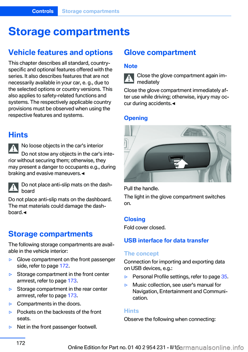
Opening
Pull the handle.
The light in the glove compartment switches
on.
ClosingFold cover closed.
USB interface for data transfer
The concept Connection for importing and exporting data
on USB devices, e.g.:
▷Personal Profile settings, refer to page 35.▷Music collection, see user's manual for
Navigation, Entertainment and Communi‐
cation.
Hints
Observe the following when connecting:
Seite 172ControlsStorage compartments172
Online Edition for Part no. 01 40 2 954 231 - II/15