2015 BMW 6 SERIES COUPE light
[x] Cancel search: lightPage 185 of 251
Overview
The system includes the following
EfficientDynamics functions and displays:▷ECO PRO bonus range, refer to page 181.▷ECO PRO tips driving instruction, refer to
page 182▷ECO PRO climate control, refer to
page 181.▷ECO PRO coasting driving status, refer to
page 183.
Activate ECO PRO
Press button repeatedly until ECO
PRO is displayed in the instrument
cluster.
Configuring ECO PRO
Via the Driving Dynamics Control
1.Activate ECO PRO.2."Configure ECO PRO"3.Configure the program.
Via the iDrive
1."Settings"2."Driving mode"3."Configure ECO PRO"
Configure the program.
ECO PRO Tip
▷"Tip at:":
Adjust the ECO PRO speed.▷"ECO PRO speed warning":
The output is reduced once the set ECO
PRO speed is reached.
Coasting
Fuel-efficiency can be optimized by disengag‐
ing the engine and Coasting, refer to
page 183, with the engine idling.
This function is only available in ECO PRO
mode.
ECO PRO climate control
"ECO PRO climate control"
Climate control is set to be fuel-efficient.
By making a slight change to the set tempera‐
ture, or slowly adjusting the rate of heating or
cooling of the car's interior, fuel consumption
can be economized.
The mirror heating is made available when out‐
side temperatures are very cold.
ECO PRO potential Shows potential savings with the current set‐
tings in percentages.
Display in the instrument cluster
Display in the instrument display
When ECO PRO mode is activated, the display
switches to a special configuration.
Some of the displays may differ from the dis‐
play in the instrument cluster.
Blue bar segments symbolize the gained bo‐
nus range in stages.
In addition, the bonus range is highlighted in
blue in the total range display.
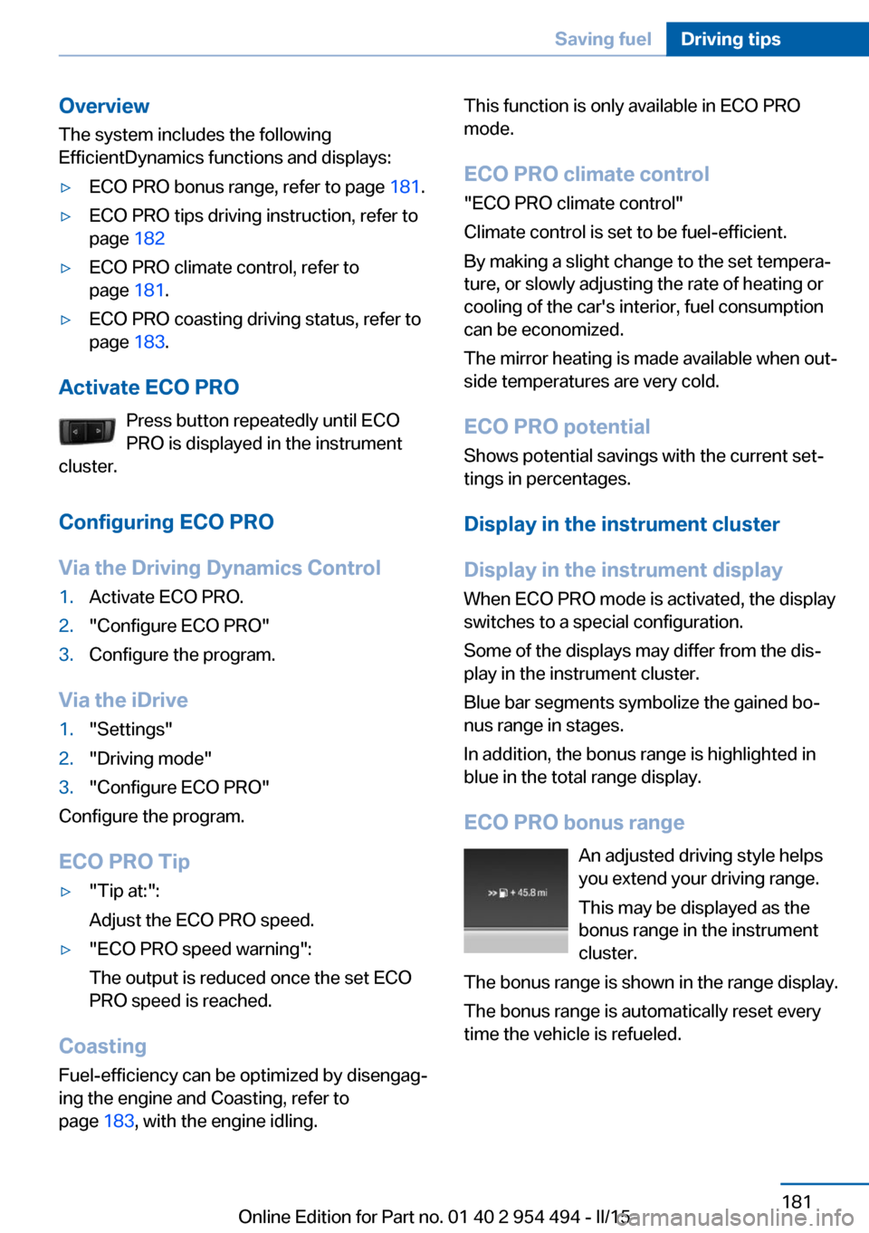
ECO PRO bonus range An adjusted driving style helps
you extend your driving range.
This may be displayed as the
bonus range in the instrument
cluster.
The bonus range is shown in the range display.
The bonus range is automatically reset every
time the vehicle is refueled.Seite 181Saving fuelDriving tips181
Online Edition for Part no. 01 40 2 954 494 - II/15
Page 206 of 251
StorageStore wheels and tires in a cool, dry place with
as little exposure to light as possible.
Always protect tires against all contact with oil,
grease and fuels.
Do not exceed the maximum tire inflation pres‐
sure indicated on the side wall of the tire.
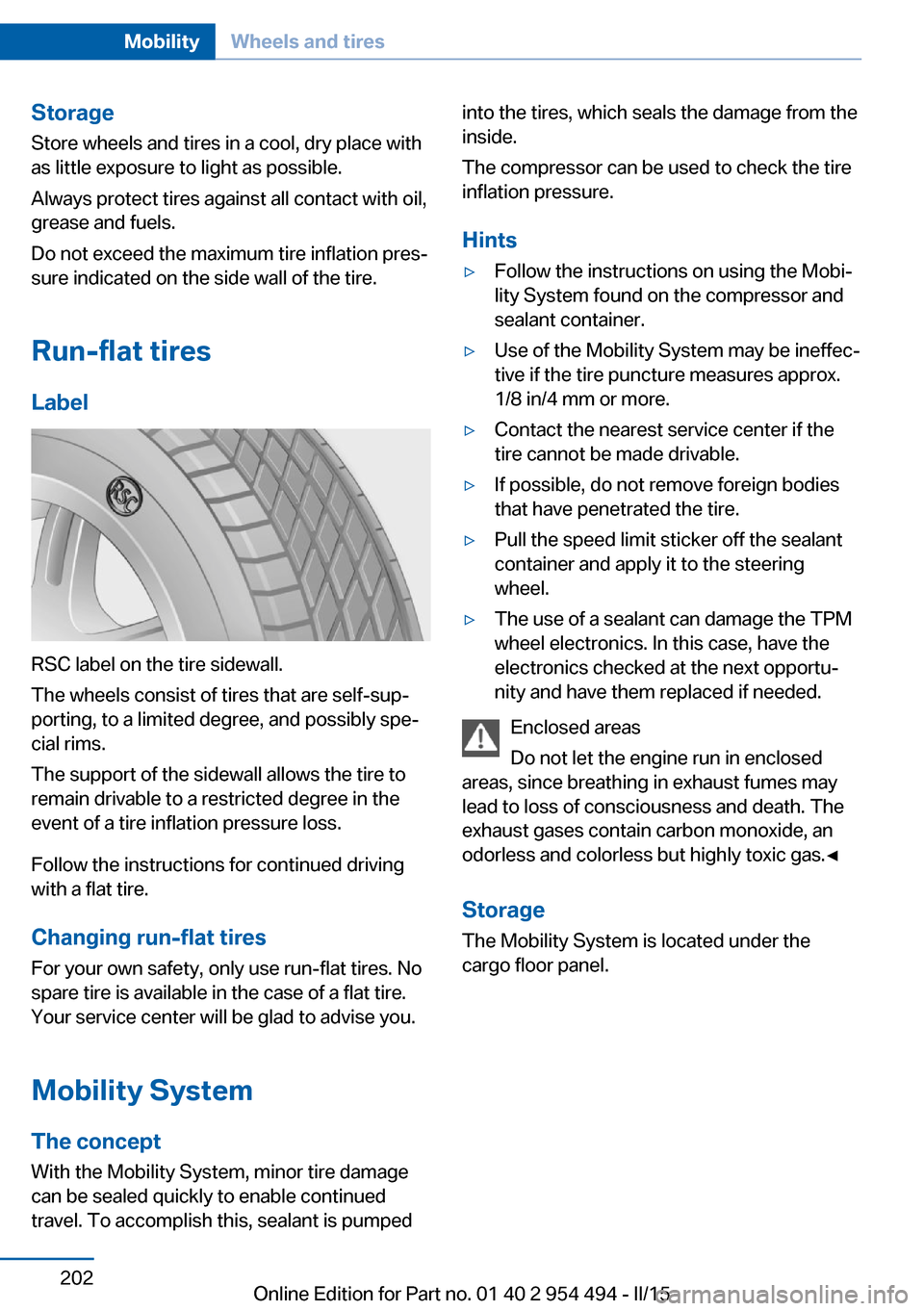
Run-flat tires Label
RSC label on the tire sidewall.
The wheels consist of tires that are self-sup‐
porting, to a limited degree, and possibly spe‐
cial rims.
The support of the sidewall allows the tire to
remain drivable to a restricted degree in the
event of a tire inflation pressure loss.
Follow the instructions for continued driving
with a flat tire.
Changing run-flat tires
For your own safety, only use run-flat tires. No
spare tire is available in the case of a flat tire.
Your service center will be glad to advise you.
Mobility System
The concept With the Mobility System, minor tire damagecan be sealed quickly to enable continued
travel. To accomplish this, sealant is pumped
into the tires, which seals the damage from the inside.
The compressor can be used to check the tire inflation pressure.
Hints▷Follow the instructions on using the Mobi‐
lity System found on the compressor and
sealant container.▷Use of the Mobility System may be ineffec‐
tive if the tire puncture measures approx.
1/8 in/4 mm or more.▷Contact the nearest service center if the
tire cannot be made drivable.▷If possible, do not remove foreign bodies
that have penetrated the tire.▷Pull the speed limit sticker off the sealant
container and apply it to the steering
wheel.▷The use of a sealant can damage the TPM
wheel electronics. In this case, have the
electronics checked at the next opportu‐
nity and have them replaced if needed.
Enclosed areas
Do not let the engine run in enclosed
areas, since breathing in exhaust fumes may
lead to loss of consciousness and death. The
exhaust gases contain carbon monoxide, an
odorless and colorless but highly toxic gas.◀
Storage The Mobility System is located under the
cargo floor panel.
Seite 202MobilityWheels and tires202
Online Edition for Part no. 01 40 2 954 494 - II/15
Page 216 of 251
CoolantVehicle features and optionsThis chapter describes all standard, country-
specific and optional features offered with the
series. It also describes features that are not
necessarily available in your car, e. g., due to
the selected options or country versions. This
also applies to safety-related functions and
systems. The respectively applicable country
provisions must be observed when using the
respective features and systems.
Hints Danger of burns from hot engine
Do not open the cooling system while
the engine is hot; otherwise, esliding coolant
may cause burns.◀
Suitable additives
Only use suitable additives; otherwise,
engine damage may occur. The additives are
harmful to your health.◀
Coolant consists of water and additives.
Not all commercially available additives are
suitable for the vehicle. Information about the
suitable additives are available from the service
center.
Coolant level
General information
If there is no Min. and Max. mark in the filler
neck of the coolant reservoir, have the coolant
level checked if needed by your service center
and add coolant as needed.
Depending on the engine installation, the cool‐
ant reservoir is located on the right side or the
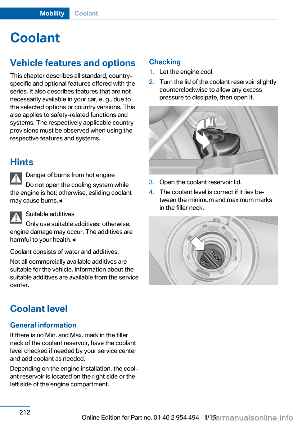
left side of the engine compartment.Checking1.Let the engine cool.2.Turn the lid of the coolant reservoir slightly
counterclockwise to allow any excess
pressure to dissipate, then open it.3.Open the coolant reservoir lid.4.The coolant level is correct if it lies be‐
tween the minimum and maximum marks
in the filler neck.Seite 212MobilityCoolant212
Online Edition for Part no. 01 40 2 954 494 - II/15
Page 217 of 251
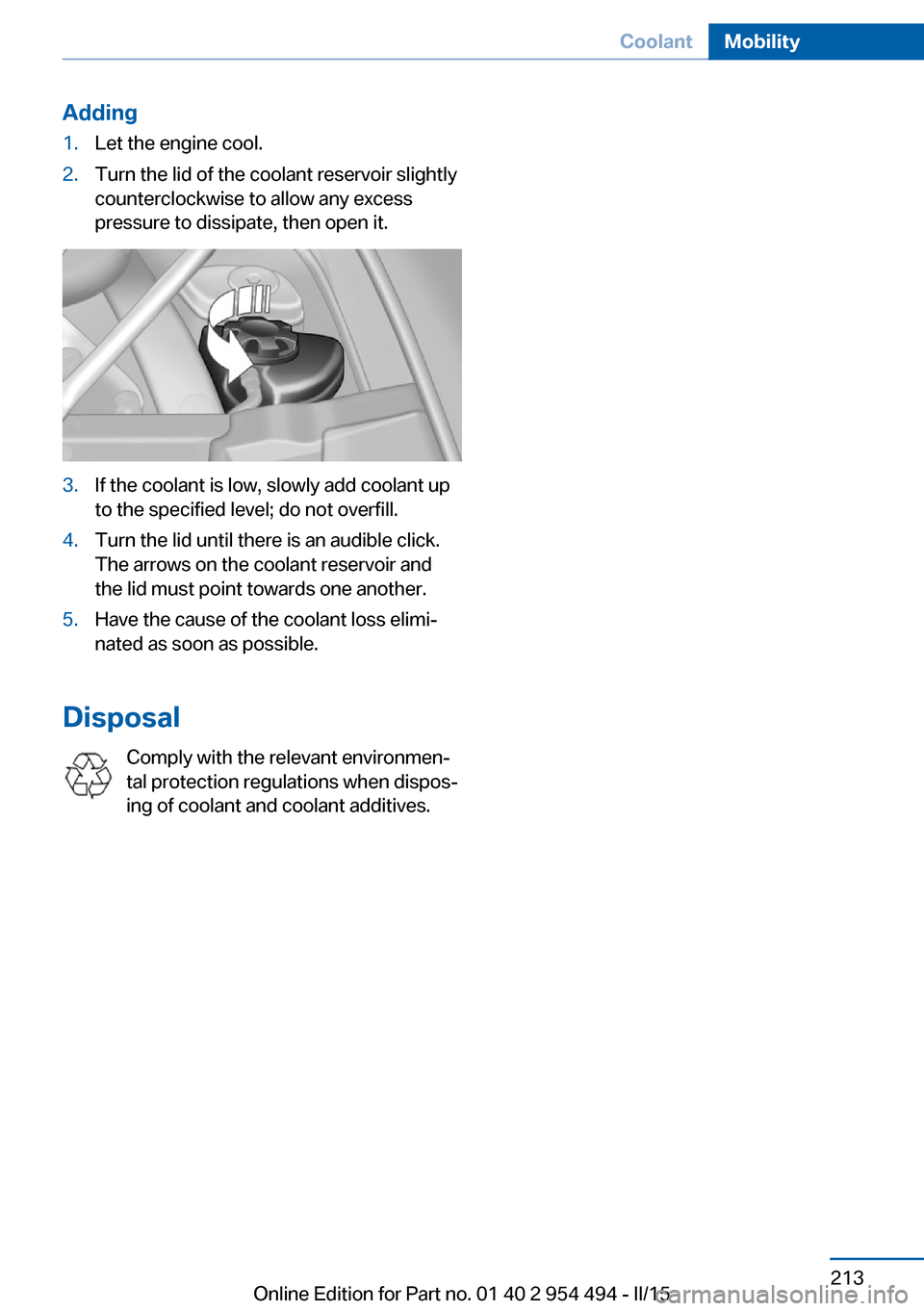
Adding1.Let the engine cool.2.Turn the lid of the coolant reservoir slightly
counterclockwise to allow any excess
pressure to dissipate, then open it.3.If the coolant is low, slowly add coolant up
to the specified level; do not overfill.4.Turn the lid until there is an audible click.
The arrows on the coolant reservoir and
the lid must point towards one another.5.Have the cause of the coolant loss elimi‐
nated as soon as possible.
Disposal
Comply with the relevant environmen‐
tal protection regulations when dispos‐
ing of coolant and coolant additives.
Seite 213CoolantMobility213
Online Edition for Part no. 01 40 2 954 494 - II/15
Page 219 of 251
Socket for OBD Onboard
Diagnosis
Note Socket for Onboard Diagnosis
The socket for onboard diagnostics may
only be used by the service center or a work‐
shop that operates in accordance with the
specifications of the vehicle manufacturer with
correspondingly trained personnel and other
authorized persons. Otherwise, use may result
in operating problems for the vehicle.◀
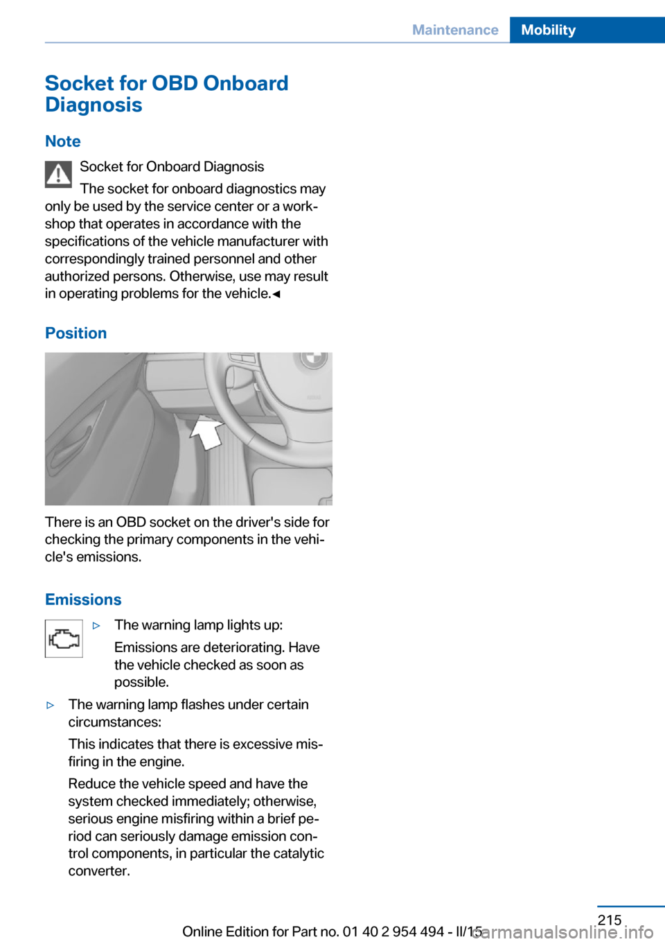
Position
There is an OBD socket on the driver's side for
checking the primary components in the vehi‐
cle's emissions.
Emissions
▷The warning lamp lights up:
Emissions are deteriorating. Have
the vehicle checked as soon as
possible.▷The warning lamp flashes under certain
circumstances:
This indicates that there is excessive mis‐
firing in the engine.
Reduce the vehicle speed and have the
system checked immediately; otherwise,
serious engine misfiring within a brief pe‐
riod can seriously damage emission con‐
trol components, in particular the catalytic
converter.Seite 215MaintenanceMobility215
Online Edition for Part no. 01 40 2 954 494 - II/15
Page 220 of 251
Replacing componentsVehicle features and optionsThis chapter describes all standard, country-
specific and optional features offered with the
series. It also describes features that are not
necessarily available in your car, e. g., due to
the selected options or country versions. This
also applies to safety-related functions and
systems. The respectively applicable country
provisions must be observed when using the
respective features and systems.
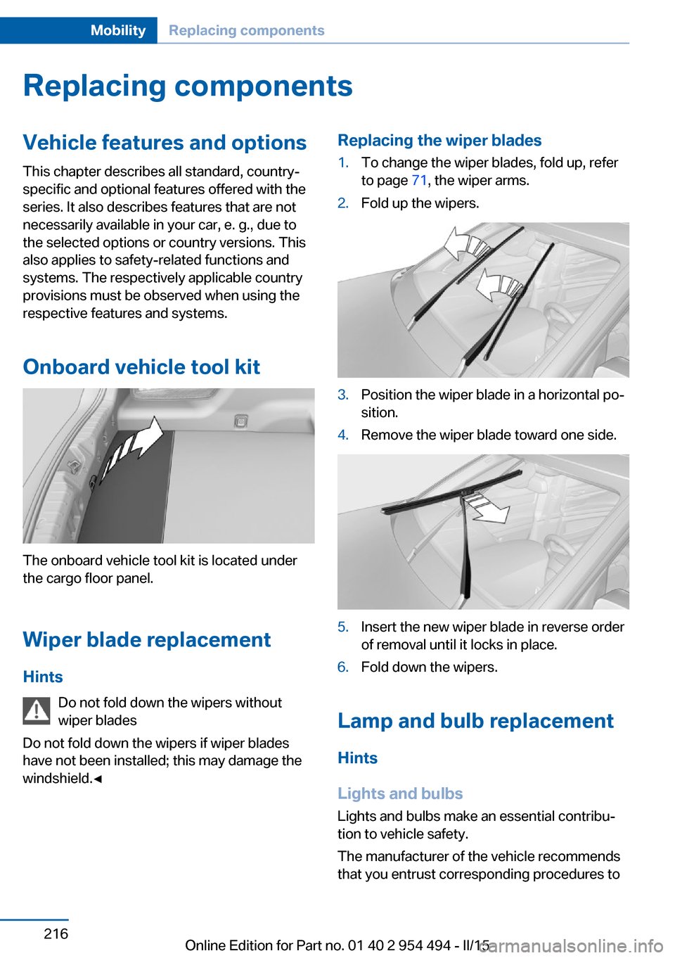
Onboard vehicle tool kit
The onboard vehicle tool kit is located under
the cargo floor panel.
Wiper blade replacement Hints Do not fold down the wipers without
wiper blades
Do not fold down the wipers if wiper blades
have not been installed; this may damage the
windshield.◀
Replacing the wiper blades1.To change the wiper blades, fold up, refer
to page 71, the wiper arms.2.Fold up the wipers.3.Position the wiper blade in a horizontal po‐
sition.4.Remove the wiper blade toward one side.5.Insert the new wiper blade in reverse order
of removal until it locks in place.6.Fold down the wipers.
Lamp and bulb replacement
Hints
Lights and bulbs
Lights and bulbs make an essential contribu‐
tion to vehicle safety.
The manufacturer of the vehicle recommends
that you entrust corresponding procedures to
Seite 216MobilityReplacing components216
Online Edition for Part no. 01 40 2 954 494 - II/15
Page 221 of 251

the service center if you are unfamiliar those or
if they have not been described here.
You can obtain a selection of replacement
bulbs at the service center.
Danger of burns
Only change bulbs when they are cool;
otherwise, there is a danger of getting
burned.◀
Working on the lighting system
When working on the lighting system,
you should always reel off the lights affected to
prevent short circuits.
To avoid possible injury or equipment damage
when replacing bulbs, observe any instructions
provided by the bulb manufacturer.◀
Do not touch the bulbs
Do not touch the glass of new bulbs with
your bare hands, as even minute amounts of
contamination will burn into the bulb's surface
and reduce its service life.
Use a clean tissue, cloth or something similar,
or hold the bulb by its base.◀
Light-emitting diodes (LEDs)
Some items of equipment use light-emitting
diodes installed behind a cover as a light
source.
These light-emitting diodes, which are related
to conventional lasers, are officially designated as Class 1 light-emitting diodes.
Do not remove the covers
Do not remove the covers, and never
stare into the unfiltered light for several hours;
otherwise, irritation of the retina could result.◀
Headlight glass
Condensation can form on the inside of the ex‐
ternal lights in cool or humid weather. When
driving with the light switched on, the conden‐
sation evaporates after a short time. The head‐
light glass does not need to be changed.If the headlights do not dim despite driving
with the light switched on, increasing humidity
forms, e. g. water droplets in the light, have the
service center check this.
Headlight setting The headlight adjustments can be affected by
changing lights and bulbs. Have the head‐
lights' settings checked and corrected by serv‐
ice after a replacement.
Front lights, bulb replacement LED headlights Overview1Corner-illuminating lights2Low beams/high beams3Parking lamp, daytime running lights4Turn signal5Side marker lights
Light-emitting diodes (LEDs)
With LED headlights, all front lights and side
indicators are designed with LED technology.
If an LED fails, switch on the front fog lights
and continue the trip with great care. Comply
with local regulations.
Contact your service center in the event of a
malfunction.
Seite 217Replacing componentsMobility217
Online Edition for Part no. 01 40 2 954 494 - II/15
Page 222 of 251
LED front fog lights
These front fog lights are made using LED
technology. Contact your service center in the
event of a malfunction.
Turn signal in exterior mirror The turn signals in the exterior mirrors feature
LED technology. Contact your service center in the event of a malfunction.
Tail lights, bulb replacement
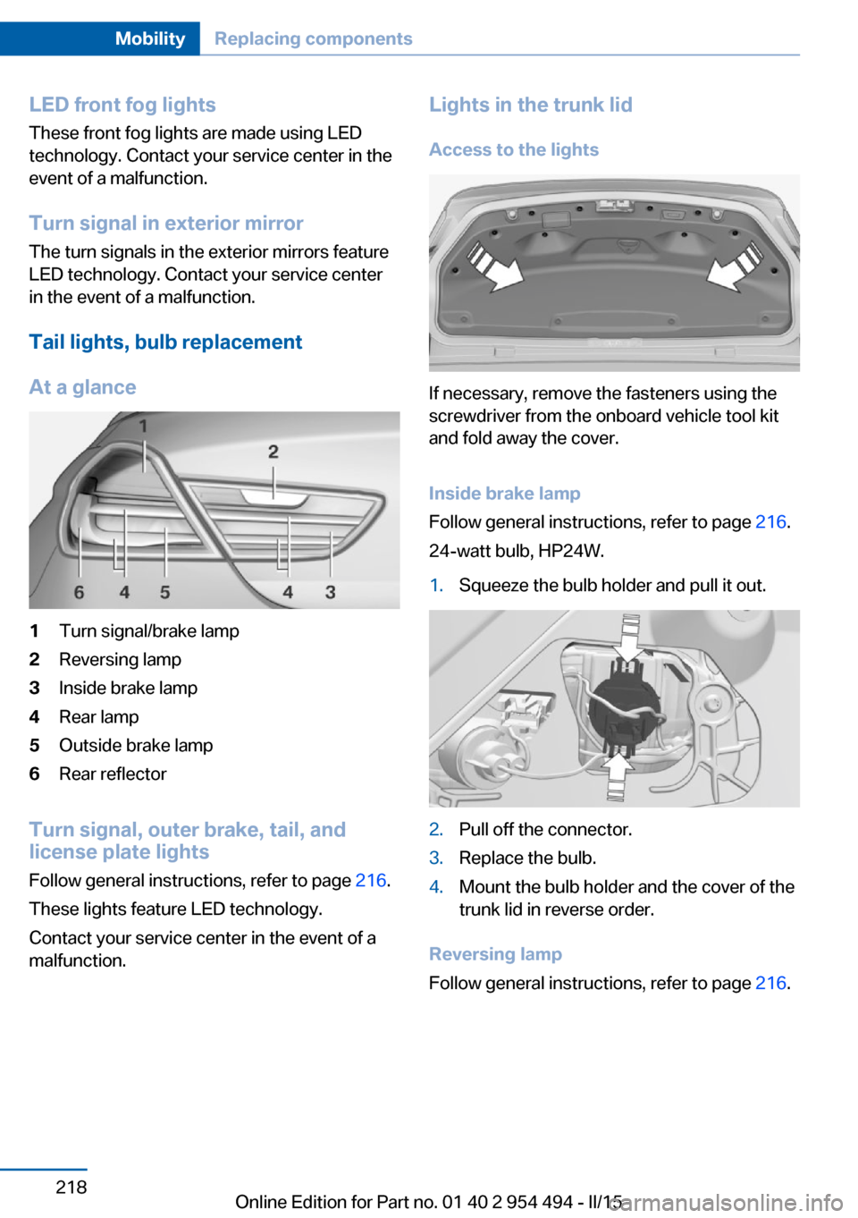
At a glance1Turn signal/brake lamp2Reversing lamp3Inside brake lamp4Rear lamp5Outside brake lamp6Rear reflector
Turn signal, outer brake, tail, and
license plate lights
Follow general instructions, refer to page 216.
These lights feature LED technology.
Contact your service center in the event of a
malfunction.
Lights in the trunk lid
Access to the lights
If necessary, remove the fasteners using the
screwdriver from the onboard vehicle tool kit
and fold away the cover.
Inside brake lamp
Follow general instructions, refer to page 216.
24-watt bulb, HP24W.
1.Squeeze the bulb holder and pull it out.2.Pull off the connector.3.Replace the bulb.4.Mount the bulb holder and the cover of the
trunk lid in reverse order.
Reversing lamp
Follow general instructions, refer to page 216.
Seite 218MobilityReplacing components218
Online Edition for Part no. 01 40 2 954 494 - II/15