2015 BMW 5 SERIES SEDAN flat tire
[x] Cancel search: flat tirePage 228 of 277

Retreaded tires
Possibly substantial variations in the de‐
sign and age of the tire casing structures can
limit service life and have a negative impact on
road safety.◀
Winter tires
Winter tires are recommended for operating on
winter roads.
Although so-called all-season M+S tires pro‐
vide better winter traction than summer tires, they do not provide the same level of perform‐
ance as winter tires.
Maximum speed of winter tires If the maximum speed of the vehicle is higher
than the permissible speed for the winter tires,
then a respective symbol is displayed in your
field of vision. You can obtain this sign from the
tire specialist or from your service center.
Maximum speed for winter tires
Do not exceed the maximum speed for
the respective winter tires; otherwise, tire dam‐
age and accidents can occur.◀
Run-flat tires If you are already using run-flat tires, for your
own safety you should replace them only with
the same kind. No spare tire is available in the
case of a flat tire. Your service center will be
glad to advise you.
Rotating wheels between axlesDifferent wear patterns can occur on the frontand rear axles depending on individual driving
conditions. The tires can be rotated between
the axles to achieve even wear. Your service
center will be glad to advise you. After rotating,
check the tire pressure and correct if needed.
Rotating the tires is not permissible on vehi‐
cles with different tire sizes or rim sizes on the
front and rear axles.Storage
Store wheels and tires in a cool, dry place with
as little exposure to light as possible.
Always protect tires against all contact with oil,
grease and fuels.
Do not exceed the maximum tire inflation pres‐
sure indicated on the side wall of the tire.
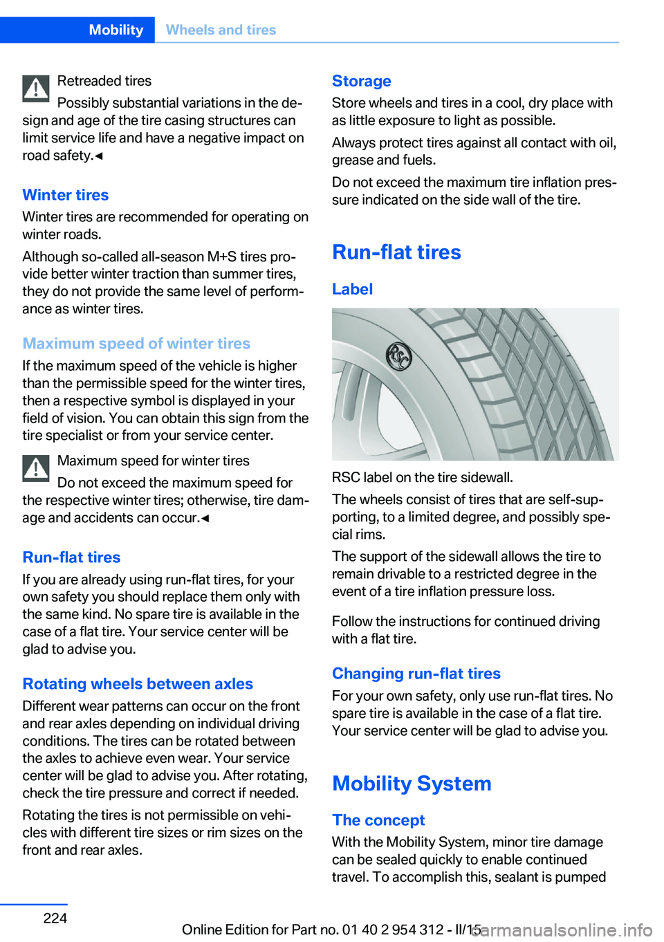
Run-flat tires Label
RSC label on the tire sidewall.
The wheels consist of tires that are self-sup‐
porting, to a limited degree, and possibly spe‐
cial rims.
The support of the sidewall allows the tire to
remain drivable to a restricted degree in the
event of a tire inflation pressure loss.
Follow the instructions for continued driving
with a flat tire.
Changing run-flat tires
For your own safety, only use run-flat tires. No
spare tire is available in the case of a flat tire.
Your service center will be glad to advise you.
Mobility System
The concept With the Mobility System, minor tire damagecan be sealed quickly to enable continued
travel. To accomplish this, sealant is pumped
Seite 224MobilityWheels and tires224
Online Edition for Part no. 01 40 2 954 312 - II/15
Page 229 of 277

into the tires, which seals the damage from the
inside.
The compressor can be used to check the tire
inflation pressure.
Hints▷Follow the instructions on using the Mobi‐
lity System found on the compressor and
sealant container.▷Use of the Mobility System may be ineffec‐
tive if the tire puncture measures approx.
1/8 in/4 mm or more.▷Contact the nearest service center if the
tire cannot be made drivable.▷If possible, do not remove foreign bodies
that have penetrated the tire.▷Pull the speed limit sticker off the sealant
container and apply it to the steering
wheel.▷The use of a sealant can damage the TPM
wheel electronics. In this case, have the
electronics checked at the next opportu‐
nity and have them replaced if needed.
Enclosed areas
Do not let the engine run in enclosed
areas, since breathing in exhaust fumes may
lead to loss of consciousness and death. The
exhaust gases contain carbon monoxide, an
odorless and colorless but highly toxic gas.◀
Storage The Mobility System is located under the
cargo floor panel.
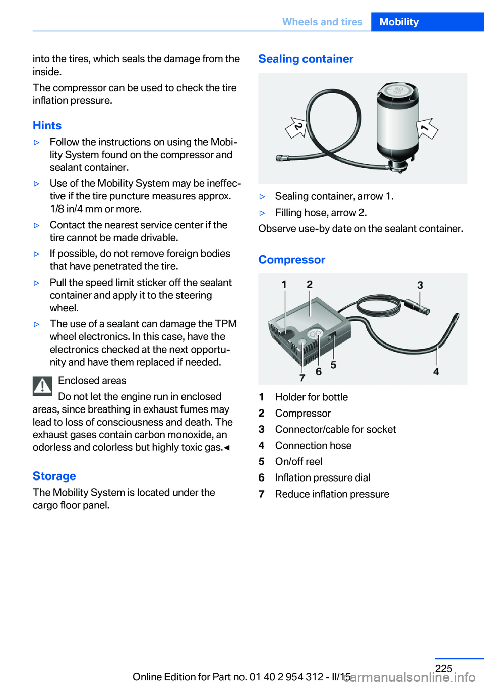
Sealing container▷Sealing container, arrow 1.▷Filling hose, arrow 2.
Observe use-by date on the sealant container.
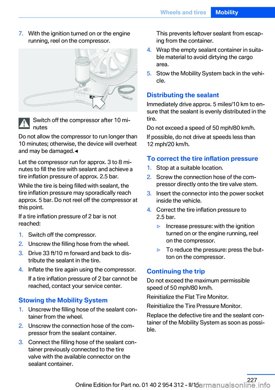
Compressor
1Holder for bottle2Compressor3Connector/cable for socket4Connection hose5On/off reel6Inflation pressure dial7Reduce inflation pressureSeite 225Wheels and tiresMobility225
Online Edition for Part no. 01 40 2 954 312 - II/15
Page 231 of 277

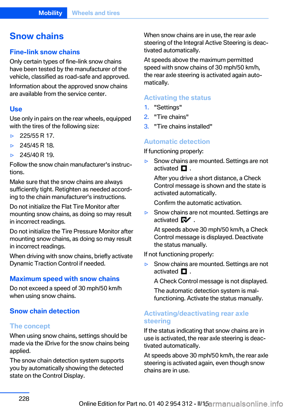
7.With the ignition turned on or the engine
running, reel on the compressor.
Switch off the compressor after 10 mi‐
nutes
Do not allow the compressor to run longer than
10 minutes; otherwise, the device will overheat
and may be damaged.◀
Let the compressor run for approx. 3 to 8 mi‐
nutes to fill the tire with sealant and achieve a
tire inflation pressure of approx. 2.5 bar.
While the tire is being filled with sealant, the
tire inflation pressure may sporadically reach
approx. 5 bar. Do not reel off the compressor at
this point.
If a tire inflation pressure of 2 bar is not
reached:
1.Switch off the compressor.2.Unscrew the filling hose from the wheel.3.Drive 33 ft/10 m forward and back to dis‐
tribute the sealant in the tire.4.Inflate the tire again using the compressor.
If a tire inflation pressure of 2 bar cannot be
reached, contact your service center.
Stowing the Mobility System
1.Unscrew the filling hose of the sealant con‐
tainer from the wheel.2.Unscrew the connection hose of the com‐
pressor from the sealant container.3.Connect the filling hose of the sealant con‐
tainer previously connected to the tire
valve with the available connector on the
sealant container.This prevents leftover sealant from escap‐
ing from the container.4.Wrap the empty sealant container in suita‐
ble material to avoid dirtying the cargo
area.5.Stow the Mobility System back in the vehi‐
cle.
Distributing the sealant
Immediately drive approx. 5 miles/10 km to en‐
sure that the sealant is evenly distributed in the
tire.
Do not exceed a speed of 50 mph/80 km/h.
If possible, do not drive at speeds less than
12 mph/20 km/h.
To correct the tire inflation pressure
1.Stop at a suitable location.2.Screw the connection hose of the com‐
pressor directly onto the tire valve stem.3.Insert the connector into the power socket
inside the vehicle.4.Correct the tire inflation pressure to
2.5 bar.▷Increase pressure: with the ignition
turned on or the engine running, reel
on the compressor.▷To reduce the pressure: press the but‐
ton on the compressor.
Continuing the trip
Do not exceed the maximum permissible
speed of 50 mph/80 km/h.
Reinitialize the Flat Tire Monitor.
Reinitialize the Tire Pressure Monitor.
Replace the defective tire and the sealant con‐
tainer of the Mobility System as soon as possi‐
ble.
Seite 227Wheels and tiresMobility227
Online Edition for Part no. 01 40 2 954 312 - II/15
Page 232 of 277

Snow chains
Fine-link snow chains Only certain types of fine-link snow chains
have been tested by the manufacturer of the
vehicle, classified as road-safe and approved.
Information about the approved snow chains
are available from the service center.
Use Use only in pairs on the rear wheels, equipped
with the tires of the following size:▷225/55 R 17.▷245/45 R 18.▷245/40 R 19.
Follow the snow chain manufacturer's instruc‐
tions.
Make sure that the snow chains are always
sufficiently tight. Retighten as needed accord‐
ing to the chain manufacturer's instructions.
Do not initialize the Flat Tire Monitor after
mounting snow chains, as doing so may result
in incorrect readings.
Do not initialize the Tire Pressure Monitor after
mounting snow chains, as doing so may result
in incorrect readings.
When driving with snow chains, briefly activate
Dynamic Traction Control if needed.
Maximum speed with snow chains Do not exceed a speed of 30 mph/50 km/hwhen using snow chains.
Snow chain detection
The concept When using snow chains, settings should bemade via the iDrive for the snow chains being
applied.
The snow chain detection system supports
you by automatically showing the detected
state on the Control Display.
When snow chains are in use, the rear axle
steering of the Integral Active Steering is deac‐
tivated automatically.
At speeds above the maximum permitted
speed with snow chains of 30 mph/50 km/h,
the rear axle steering is activated again auto‐
matically.
Activating the status1."Settings"2."Tire chains"3."Tire chains installed"
Automatic detection If functioning properly:
▷Snow chains are mounted. Settings are not
activated
.
After you drive a short distance, a Check
Control message is shown and the state is
activated automatically.
Confirm the automatic activation.
▷Snow chains are not mounted. Settings are
activated
.
At speeds above 30 mph/50 km/h, a Check
Control message is displayed. Deactivate
the status manually.
If not functioning properly:
▷Snow chains are mounted. Settings are not
activated
.
A Check Control message is not displayed.
The automatic detection system is mal‐
functioning. Activate the status manually.
Activating/deactivating rear axle
steering
If the status indicating that snow chains are in
use is activated, the rear axle steering is deac‐
tivated automatically.
At speeds above 30 mph/50 km/h, the rear axle
steering is activated again, even though snow
chains are in use.
Seite 228MobilityWheels and tires228
Online Edition for Part no. 01 40 2 954 312 - II/15
Page 247 of 277

Changing wheels
Hints
When using run-flat tires or sealants, a tire
does not need to be changed immediately in
the event of pressure loss due to a flat tire.
Which is why no spare tire is available.
The tools for changing wheels are available as
accessories from your service center.
Jacking points for the vehicle jack
The jacking points for the vehicle jack are lo‐
cated at the positions shown.
Vehicle battery Maintenance
The battery is maintenance-free.
The added amount of acid is sufficient for the
service life of the battery.
Further information about the battery can be
obtained from your service center.
Battery replacement Use approved vehicle batteries only
Only use vehicle batteries that have been
approved for your vehicle by the manufacturer;
otherwise, the vehicle could be damaged and
systems or functions may not be fully availa‐
ble.◀
After a battery replacement, have the battery
registered on the vehicle by the service center
to ensure that all comfort features are fully
available and that any Check Control mes‐
sages of these comfort features are no longer
displayed.
Charging the battery
General information
Make sure that the battery is always suffi‐
ciently charged to guarantee that the battery
remains usable for its full service life.
The battery may need to be charged in the fol‐
lowing cases:▷When making frequent short-distance
drives.▷If the vehicle is not used for prolonged pe‐
riods, longer than a month.
Hints
Do not connect charging devices to the
12 volt socket in the vehicle
Do not connect battery chargers to the fac‐
tory-installed 12 volt sockets in the vehicle as
this may damage the vehicle battery due to an
increased power consumption.◀
Starting aid terminals
In the vehicle, only charge the battery via the
starting aid terminals, refer to page 247, in the
engine compartment with the engine off.
Power failure
After a temporary power loss, some equipment
needs to be newly initialized or individual set‐
tings updated, e. g.:
▷Seat, mirror, and steering wheel memory:
store the positions again.▷Time: update.▷Date: update.▷Glass sunroof: initialize the system, refer to
page 51.Seite 243Replacing componentsMobility243
Online Edition for Part no. 01 40 2 954 312 - II/15
Page 268 of 277

COMFORT program, DrivingDynamics Control 141
Compressor 224
Computer, refer to On-board computer 97
Condensation on win‐ dows 166
Condensation under the vehi‐ cle 191
Condition Based Service CBS 236
Configure driving mode 141
Confirmation signal 46
ConnectedDrive, see user's manual for Navigation, En‐
tertainment and Communi‐
cation
ConnectedDrive Services
Continued driving with a flat tire 113 , 116
Control Display 18
Control Display, settings 99
Controller 18
Control systems, driving sta‐ bility 135
Convenient opening with the remote control 37
Coolant 234
Coolant level 234
Coolant temperature 92
Cooling function 167
Cooling, maximum 167
Cooling system 234
Cornering light 104
Corrosion on brake discs 190
Cosmetic mirror 174
Courtesy lamps during un‐ locking 37
Courtesy lamps with the vehi‐ cle locked 38
Cruise control 150
Cruise control, active with Stop & Go 143
Cruise Control, refer to Active Cruise Control 143
Cruising range 93 Cupholder 183
Current fuel consumption 93
D
Damage, tires 222
Damping control, dy‐ namic 138
Data, technical 258
Date 93
Daytime running lights 104
Defrosting, refer to Windows, defrosting 166
Dehumidifying, air 167
Deleting personal data 24
Deletion of personal data 24
Destination distance 98
Diesel exhaust fluid, at low temperatures 208
Diesel exhaust fluid, having refilled 208
Diesel exhaust fluid, on mini‐ mum 208
Diesel exhaust fluid, replen‐ ishing yourself 208
Diesel particulate filter 189
Digital clock 93
Dimensions 258
Dimmable exterior mirrors 63
Dimmable interior rearview mirror 63
Direction indicator, refer to Turn signals 76
Display, electronic, instru‐ ment cluster 84
Display in windshield 101
Display lighting, refer to In‐ strument lighting 106
Displays 85
Displays, cleaning 254
Disposal, coolant 235
Disposal, vehicle battery 244
Distance control, refer to PDC 152
Distance to destination 98 Divided screen view, split
screen 23
Door lock 39
Door lock, refer to Remote control 34
Doors, Automatic Soft Clos‐ ing 40
Downhill control 137
Drive-off assistant 135
Drive-off assistant, refer to DSC 135
Driver assistance, refer to In‐ telligent Safety 117
Driving Assistant, refer to In‐ telligent Safety 117
Driving Dynamics Con‐ trol 139
Driving instructions, break- in 188
Driving mode 139
Driving notes, general 188
Driving stability control sys‐ tems 135
Driving tips 188
DSC Dynamic Stability Con‐ trol 135
DTC Dynamic Traction Con‐ trol 136
Dynamic Damping Con‐ trol 138
Dynamic Drive 138
Dynamic Stability Control DSC 135
Dynamic Traction Control DTC 136
E ECO PRO 196
ECO PRO, bonus range 197
ECO PRO display 196
ECO PRO displays 86
ECO PRO driving mode 196
ECO PRO mode 196
ECO PRO Tip - driving in‐ struction 198 Seite 264ReferenceEverything from A to Z264
Online Edition for Part no. 01 40 2 954 312 - II/15
Page 269 of 277

EfficientDynamics 199
Electronic displays, instru‐ ment cluster 84
Electronic oil measure‐ ment 231
Electronic Stability Program ESP, refer to DSC 135
Emergency detection, remote control 35
Emergency release, fuel filler flap 204
Emergency Request 245
Emergency start function, en‐ gine start 35
Emergency unlocking, trans‐ mission lock 82
Emergency unlocking, trunk lid 43
Energy Control 93
Energy recovery 94
Engine, automatic Start/Stop function 71
Engine, automatic switch- off 71
Engine compartment 229
Engine compartment, work‐ ing in 229
Engine coolant 234
Engine idling when driving, coasting 199
Engine oil 231
Engine oil, adding 232
Engine oil additives 233
Engine oil change 233
Engine oil filler neck 232
Engine oil temperature 92
Engine oil types, alterna‐ tive 233
Engine oil types, ap‐ proved 233
Engine start during malfunc‐ tion 35
Engine start, jump-start‐ ing 246
Engine start, refer to Starting the engine 70 Engine stop 71
Engine temperature 92
Entering a car wash 251
Equipment, interior 172
Error displays, see Check Control 88
ESP Electronic Stability Pro‐ gram, refer to DSC 135
Exchanging wheels/tires 223
Exhaust system 189
Exterior mirror, automatic dimming feature 63
Exterior mirrors 62
External start 246
External temperature dis‐ play 93
External temperature warn‐ ing 93
Eyes for securing cargo 193
F
Failure message, see Check Control 88
False alarm, refer to Uninten‐ tional alarm 48
Fan, refer to Air flow 166
Filler neck for engine oil 232
Fine wood, care 253
First aid kit 246
Fitting for towing, see Tow fit‐ ting 249
Flat tire, changing wheels 243
Flat Tire Monitor FTM 115
Flat tire, Tire Pressure Moni‐ tor TPM 111
Flat tire, warning lamp 112, 115
Flooding 190
Floor carpet, care 254
Floor mats, care 254
Fold down the rear seat back‐ rest, see Though-loading
system 177
Fold-out position, wiper 78 Foot brake 190
Front airbags 108
Front-end collision warning with braking function 120
Front-end collision warning with City Braking func‐
tion 118
Front fog lights 106
Front fog lights, bulb replace‐ ment 241
Front lights 239
front-seat passenger airbags, automatic deactivation 110
Front-seat passenger airbags, indicator lamp 110
FTM Flat Tire Monitor 115
Fuel 206
Fuel consumption, refer to Average fuel consump‐
tion 98
Fuel filler flap 204
Fuel gauge 92
Fuel lid 204
Fuel quality 206
Fuel recommendation 206
Fuel, tank capacity 261
Fuse 244
G
Garage door opener, refer to Universal Integrated Remote
Control 172
Gasoline 206
Gear change, Steptronic transmission 80
Gear shift indicator 95
General driving notes 188
Glare shield 174
Glass sunroof, powered 50
Glove compartment 181
Gross vehicle weight, ap‐ proved 259 Seite 265Everything from A to ZReference265
Online Edition for Part no. 01 40 2 954 312 - II/15
Page 270 of 277

H
Handbrake, refer to Parking brake 73
Hand-held transmitter, alter‐ nating code 173
Hazard warning flashers 245
HDC Hill Descent Con‐ trol 137
Head airbags 108
Headlight control, auto‐ matic 104
Headlight courtesy delay fea‐ ture 104
Headlight courtesy delay fea‐ ture via remote control 38
Headlight flasher 76
Headlight glass 239
Headlights 239
Headlights, care 252
Headlight washer system 77
Head restraints 53
Head restraints, front 58
Head restraints, rear 60
Head-up Display 101
Head-up Display, care 254
Heavy cargo, stowing 193
Height, vehicle 258
High-beam Assistant 105
High beams 76
High beams/low beams, refer to High-beam Assistant 105
Hill Descent Control HDC 137
Hills 190
Hill start assistant, refer to Drive-off assistant 135
Hints 6
Holder for beverages 183
Homepage 6
Hood 229
Horn 14
Hotel function, trunk lid 42
Hot exhaust system 189
HUD Head-up Display 101
Hydroplaning 189 I
Ice warning, see External temperature warning 93
Icy roads, see External tem‐ perature warning 93
Identification marks, tires 220
Identification number, see ve‐ hicle identification num‐
ber 9
iDrive 18
Ignition key, refer to Remote control 34
Ignition off 69
Ignition on 69
Indication of a flat tire 112 , 115
Indicator and alarm lamps, see Check Control 88
Indicator lamp, see Check Control 88
Individual air distribution 166
Individual settings, refer to Personal Profile 35
Inflation pressure, tires 211
Inflation pressure warning FTM, tires 115
Info display, refer to On- Board computer 97
Initialization, Integral Active Steering 139
Initialize, Tire Pressure Moni‐ tor TPM 112
Initializing, Flat Tire Monitor FTM 115
Instrument cluster 84
Instrument cluster, electronic displays 84
Instrument display, multifunc‐ tional 85
Instrument lighting 106
Integral Active Steering 139
Integrated key 34
Integrated Owner's Manual in the vehicle 29 Intelligent Emergency Re‐
quest 245
Intelligent Safety 117
Intensity, AUTO pro‐ gram 166
Interior equipment 172
Interior lights 106
Interior lights during unlock‐ ing 37
Interior lights with the vehicle locked 38
Interior motion sensor 48
Interior rearview mirror, auto‐ matic dimming feature 63
Interior rearview mirror, man‐ ually dimmable 63
Internet page 6
Interval display, service re‐ quirements 94
Interval mode 77
J
Jacking points for the vehicle jack 243
Joystick, Steptronic transmis‐ sion 80
Jump-starting 246
K
Key/remote control 34
Keyless Go, refer to Comfort Access 43
Key Memory, refer to Per‐ sonal Profile 35
Kickdown, Steptronic trans‐ mission 80
Knee airbag 109
L Lamp replacement 238
Lamp replacement, front 239
Lamp replacement, rear 241
Lane departure warning 129 Seite 266ReferenceEverything from A to Z266
Online Edition for Part no. 01 40 2 954 312 - II/15