2015 BMW 5 SERIES GRAN TURISMO service
[x] Cancel search: servicePage 47 of 263

Provide edge protection
Sharp objects or those with edges can
hit the rear window while driving and damage
the heat conductors of the rear window. Pro‐
vide edge protection.◀▷Press button, arrow 1, on the inside of the
tailgate.
Pressing the button again stops the mo‐
tion.
With Comfort Access:
▷Press button on the open tailgate.
The vehicle will be locked after closing the
tailgate. The driver's door must be closed
for this purpose and the remote control
must be outside of the vehicle in the area
of the tailgate.
Pressing the button again stops the mo‐
tion.▷Press button on tailgate's exterior arrow 1.'
Pressing the button again stops the mo‐
tion.
An acoustic signal sounds and the tailgate
closes.
The closing operation is interrupted:
▷When starting the engine.▷The vehicle starts off with jerks.
Manual operation
Do not operate the tailgate manually if it
is blocked
If the tailgate is blocked, do not operate it man‐
ually as the tailgate may otherwise become
damaged and injury may result.
Contact your service center.◀
In the event of an electrical malfunction, oper‐
ate the unlocked tailgate manually with a slow
and smooth motion.
Locking separately The tailgate can be locked separately, using
the switch in the front center armrest.
▷The tailgate is locked, ar‐
row 1.
The small and large tailgates
are locked.▷The tailgate is unlocked, ar‐
row 2.
Slide the switch into the arrow 1 position. This
secures the tailgate and disconnects it from
the central locking system.
Seite 43Opening and closingControls43
Online Edition for Part no. 01 40 2 954 285 - II/15
Page 48 of 263

When the center armrest is locked, the tailgate
cannot be accessed. This is beneficial when
the vehicle is parked using valet service. The
infrared remote control can be handed out
without the key.
Emergency unlocking
Pull the handle inside the trunk.
The tailgate is unlocked.
Comfort Access
The concept The vehicle can be accessed without activat‐
ing the remote control.
All you need to do is to have the remote con‐ trol with you, such as in your pants pocket.
The vehicle automatically detects the remote
control when it is in close proximity or in the
car's interior.
Comfort Access supports the following func‐
tions:
▷Unlocking/locking of the vehicle.▷Convenient closing.▷Opening the tailgate individually▷Open/close tailgate with no-touch activa‐
tion.▷Start the engine.
Functional requirements
▷There are no external sources of interfer‐
ence nearby.▷To lock the vehicle, the remote control
must be located outside of the vehicle.▷The next unlocking and locking cycle is not
possible until after approx. 2 seconds.▷The engine can only be started if the re‐
mote control is in the vehicle.
Unlocking
Grasp the handle of a vehicle door completely,
arrow.
This corresponds with pressing the button on
the remote control.
Locking
Touch the surface on the handle of a vehicle
door, arrow, with your finger for approx. 1 sec‐
ond without grasping the door handle.
This corresponds with pressing the button on
the remote control.
To save battery power, ensure that the ignition
and all electronic systems and/or power con‐
sumers are turned off before locking the vehi‐
cle.
Seite 44ControlsOpening and closing44
Online Edition for Part no. 01 40 2 954 285 - II/15
Page 64 of 263

Unbuckling the belt1.Hold the belt firmly.2.Press the red button in the belt buckle.3.Guide the belt back into its roll-up mecha‐
nism.
Safety belt reminder for driver's and
passenger's seat
The indicator lamp lights up and a sig‐
nal sounds. Make sure that the safety
belts are positioned correctly. The
safety belt reminder is active at speeds above
approx. 6 mph/10 km/h. It can also be activated
if objects are placed on the front passenger
seat.
Safety mode In critical situations, e.g., during full brake ap‐
plication, the front safety belts tighten auto‐
matically.
If the situation passes without an accident oc‐
curring, the belt tension relaxes.
If the belt tension does not loosen automati‐
cally, stop the vehicle and unbuckle the belt
using the red button in the buckle. Fasten the
belt before continuing on your trip.
Damage to safety belts
Wear and tear after accidents or when dam‐
aged otherwise:
Have the safety belts, including the safety belt
tensioners, replaced and have the belt anchors
checked.
Check and replace safety belts
This should only be done by your service
center; otherwise, this safety feature might not
work properly.◀
Front head restraints
Correctly adjusted head restraint
A correctly adjusted head restraint reduces the
risk of injury to cervical vertebrae in the event
of an accident.
Adjusting the head restraint
Adjust the head restraints of all occupied
seats properly; otherwise, there is an increased
risk of injury in an accident.◀
Height
Adjust the head restraint so that its center is
approximately at ear level.
Distance
Adjust the distance so that the head restraint
is as close as possible to the back of the head.
Active head restraint
In the event of a rear-end collision with a cer‐
tain severity, the active head restraint automat‐
ically reduces the distance from the head.
Reduced protective function▷Do not use seat or head restraint
covers.▷Do not hang objects, e.g., clothes hangers,
on the head restraints.▷Only attach accessories approved by BMW
to the seat or head restraint.
Otherwise, the protective function of the active
head restraint will be impaired and the per‐
sonal safety of the occupants will be endan‐
gered.◀
Wear and tear after accidents or when dam‐
aged otherwise:
Have the active headrest checked and if
needed replaced.
Seite 60ControlsAdjusting60
Online Edition for Part no. 01 40 2 954 285 - II/15
Page 89 of 263

▷Messages, e.g. Check Control, refer to
page 87.▷Current fuel consumption, refer to
page 93.▷Navigation display, see User's manual for
Navigation, Entertainment and Communi‐
cation.▷Range, refer to page 92.▷Status, Driving Dynamics Control, refer to
page 139.▷Service requirements, refer to page 93.▷Speed limit detection, refer to page 94.▷Time, refer to page 92.
Multifunctional instrument display
The concept
The instrument display is a variable display. In
the event of a program change, the display
rendition adapts to the respective program
through the Driving Dynamics Control. The
change of appearance can be deactivated on
the Control Display.Some of the displays in the instrument display
may differ from the way they are shown in this
Owner's Manual.
At a glance
1Fuel gauge 912Indicator/warning lights 883Speedometer4Variable displays5Tachometer 91
Selection lists 96
ECO PRO displays 1936Engine oil temperature 91Seite 85DisplaysControls85
Online Edition for Part no. 01 40 2 954 285 - II/15
Page 93 of 263

Flashing: the conditions are not adequate for
operating the system.
The system was deactivated but applies the
brakes until you actively resume control by
pressing on the brake pedal or accelerator
pedal.
Yellow lights
Anti-lock Braking System ABS Avoid abrupt braking if possible. Brak‐
ing force boost in some cases defec‐
tive. Stop carefully. Take into account
longer brake travel. Have this checked
by the service center immediately.
DSC Dynamic Stability Control Flashing: DSC controls the drive and
braking forces. The vehicle is stabi‐
lized. Reduce speed and adapt driving
profile to the driving circumstances.
Illuminated: DSC failed. Have the system
checked by the service center.
For additional information, refer to Dynamic
Stability Control DSC, refer to page 134.
DSC Dynamic Stability Control is
deactivated or DTC Dynamic Traction
Control is activated
Dynamic Stability Control DSC is
switched off or Dynamic Traction Con‐
trol DTC is switched on.
For additional information, refer to Dynamic
Stability Control, refer to page 134, and Dy‐
namic Traction Control, refer to page 135.
Flat Tire Monitor FTM The Flat Tire Monitor signals a loss of
tire inflation pressure in a tire.Reduce your speed and stop cautiously. Avoid
sudden braking and steering maneuvers.
For more information, see Flat Tire Monitor, re‐
fer to page 110.
Tire Pressure Monitor TPM Illuminated: the Tire Pressure Monitor
signals a loss of tire inflation pressure
in a tire.
Reduce your speed and stop cautiously. Avoid
sudden braking and steering maneuvers.
Flashing and then continuously illuminated: no
flat tire or loss of tire inflation pressure can be
detected.▷Interference through systems or devices
with the same radio frequency: after leav‐
ing the area of the interference, the system
automatically becomes active again.▷TPM could not conclude the reset: perform
the reset of the system again.▷A wheel without TPM electronics is fitted:
have the service center check it if needed.▷Malfunction: have the system checked by
your service center.
For more information, see Tire Pressure Moni‐
tor, refer to page 112.
Steering system Steering system in some cases defec‐
tive.
Have the steering system checked by
the service center.
Engine functions Have the vehicle checked by the serv‐ice center.
For additional information, refer to On-
board Diagnostics socket, refer to page 224.
Seite 89DisplaysControls89
Online Edition for Part no. 01 40 2 954 285 - II/15
Page 95 of 263

Symbols
Depending on the Check Control message, the
following functions can be selected.▷ "Owner's Manual"
Display additional information about the
Check Control message in the Integrated
Owner's Manual.▷ "Service request"
Contact your service center.▷ "Roadside Assistance"
Contact Roadside Assistance.
Hiding Check Control messages
Press the onboard computer button on the
turn signal lever.
▷Some Check Control messages are dis‐
played continuously and are not cleared
until the malfunction is eliminated. If sev‐
eral malfunctions occur at once, the mes‐
sages are displayed consecutively.
These messages can be faded for approx.
8 seconds. After this time, they are dis‐
played again automatically.▷Other Check Control messages are faded
automatically after approx. 20 seconds.
They are stored and can be displayed
again later.Displaying stored Check Control
messages
On the Control Display:1."Vehicle info"2."Vehicle status"3. "Check Control"4.Select the text message.
Messages after trip completion Special messages displayed while driving are
displayed again after the ignition is switched
off.
Fuel gauge Vehicle tilt position may cause
the display to vary.
Depending on the equipment
version, the arrow beside the
fuel pump symbol shows which
side of the vehicle the fuel filler flap is on.
Hints on refueling, refer to page 200.
Tachometer Always avoid engine speeds in the red warning
field. In this range, the fuel supply is inter‐
rupted to protect the engine.
Engine oil temperature
▷Cold engine: the pointer is at
the low temperature end.
Drive at moderate engine
and vehicle speeds.▷Normal operating tempera‐
ture: the pointer is in the
middle or in the left half of
the temperature display.Seite 91DisplaysControls91
Online Edition for Part no. 01 40 2 954 285 - II/15
Page 97 of 263
Displaying the cruising rangeDepending on your vehicle's optional features,
the range can also be displayed as bar in the
instrument cluster.1."Settings"2."Instrument cluster"3."Additional indicators"
With navigation system: range with destination guidance active
If respective equipment is fitted
and destination guidance is ac‐
tive, the remaining range is dis‐ played when the destination is
reached.
Current fuel consumption
Display Depending on your vehicle's op‐
tional features, the current fuel
consumption can be displayed
in the instrument cluster. Check
whether you are currently driv‐
ing in an efficient and environmentally-friendly
manner.
Displaying the current fuel
consumption
1."Settings"2."Instrument cluster"3."Additional indicators"
The bar display for the current fuel consump‐
tion is displayed in the instrument cluster.
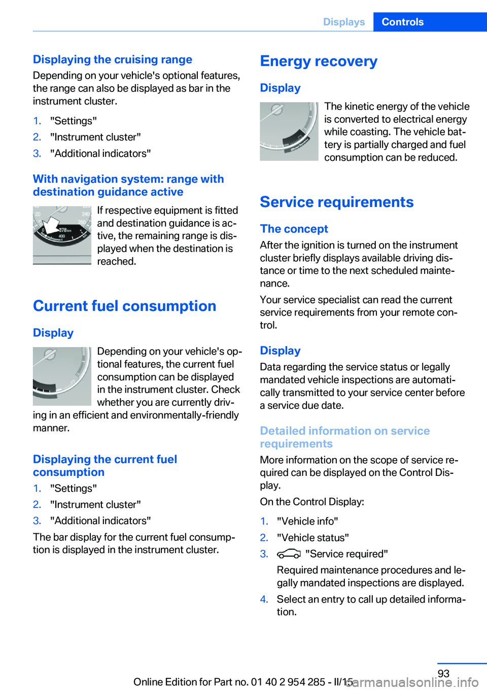
Energy recovery
Display The kinetic energy of the vehicle
is converted to electrical energy while coasting. The vehicle bat‐
tery is partially charged and fuel
consumption can be reduced.
Service requirements The concept
After the ignition is turned on the instrument
cluster briefly displays available driving dis‐
tance or time to the next scheduled mainte‐
nance.
Your service specialist can read the current
service requirements from your remote con‐
trol.
Display
Data regarding the service status or legally
mandated vehicle inspections are automati‐
cally transmitted to your service center before
a service due date.
Detailed information on service
requirements
More information on the scope of service re‐
quired can be displayed on the Control Dis‐
play.
On the Control Display:1."Vehicle info"2."Vehicle status"3. "Service required"
Required maintenance procedures and le‐
gally mandated inspections are displayed.4.Select an entry to call up detailed informa‐
tion.Seite 93DisplaysControls93
Online Edition for Part no. 01 40 2 954 285 - II/15
Page 98 of 263

SymbolsSym‐
bolsDescriptionNo service is currently required.The deadline for scheduled mainte‐
nance or a legally mandated inspec‐
tion is approaching.The service deadline has already
passed.
Entering appointment dates
Enter the dates for the required inspections.
Make sure that the vehicle's date and time are
set correctly.
On the Control Display:
1."Vehicle info"2."Vehicle status"3. "Service required"4."§ Vehicle inspection"5."Date:"6.Adjust the settings.7.Confirm.
The entered date is stored.
Automatic Service Request
Data regarding the service status or legally
mandated vehicle inspections are automati‐
cally transmitted to your service center before
a service due date.
You can check when your service center was
notified.
On the Control Display:
1."Vehicle info"2."Vehicle status"3.Open "Options".4."Last Service Request"Gear shift indicator
The conceptThe system recommends the most fuel effi‐
cient gear for the current driving situation.
Depending on the vehicle's features and coun‐
try version of the vehicle, the gear shift indica‐
tor is active in the manual mode of the Step‐
tronic transmission.
Suggestions to shift gear up or down are dis‐
played in the instrument cluster.
On vehicles without a gear shift indicator, the
engaged gear is displayed.
DisplaysExampleDescriptionFuel efficient gear is set.Shift into fuel efficient gear.
Speed limit detection
The concept
Speed limit detection
Speed limit detection uses a symbol in the
shape of a traffic sign to display the currently
detected speed limit. The camera in the area of
the interior rearview mirror detects traffic signs
at the edge of the road as well as variable over‐
head sign posts. Traffic signs with extra sym‐
bols for wet road conditions, etc. are also de‐
tected and compared with the vehicle's
onboard data, such as for the rain sensor, and
will be displayed depending on the situation.
The system takes into account the information
stored in the navigation system and also dis‐
plays speed limits present on routes without
signs.
Seite 94ControlsDisplays94
Online Edition for Part no. 01 40 2 954 285 - II/15