2015 BMW 5 SERIES GRAN TURISMO Reverse
[x] Cancel search: ReversePage 68 of 263

Automatic Curb MonitorThe concept
If reverse gear is engaged, the mirror glass on
the front passenger side is tilted downward.
This improves your view of the curb and other
low-lying obstacles when parking, e.g.
Activating1. Slide the switch to the driver's side
mirror position.2.Engage selector lever position R.
Deactivating
Slide the switch to the passenger side mirror
position.
Fold in and out Press button.
Possible at speeds up to approx.
15 mph/20 km/h.
E. g. this is advantageous
▷In car washes.▷In narrow streets.▷For folding mirrors back out that were
folded away manually.
Mirrors that were folded in are folded out auto‐
matically at a speed of approx.
25 mph/40 km/h.
Fold in the mirror in a car wash
Before washing the car in an automatic
car wash, fold in the exterior mirrors by hand or
with the button; otherwise, the mirrors could
be damaged, depending on the width of the
vehicle.◀
Automatic heating
Both exterior mirrors are automatically heated
whenever the engine is running.
Automatic dimming feature
Both exterior mirrors are automatically dim‐
med. Photocells are used to control the Interior
rearview mirror, refer to page 64.
Interior rearview mirror, manually
dimmable
Turn knob
Turn the knob to reduce the blinding effect by
the interior mirror.
Interior rearview mirror, automaticdimming feature
The concept
Photocells are used for control:
▷In the mirror glass.▷On the back of the mirror.
Functional requirement For proper operation:
▷Keep the photocells clean.Seite 64ControlsAdjusting64
Online Edition for Part no. 01 40 2 954 285 - II/15
Page 76 of 263
stop, e.g., in traffic congestion or at traffic
lights. The ignition remains switched on. The
engine starts again automatically for driving
off.
Automatic mode After every start of the engine using the Start/
Stop button, the Auto Start/Stop function is in
the last selected state, refer to page 73.
When the Auto Start/Stop function is active, it
is available when the vehicle is traveling faster
than about 3 mph, approx. 5 km/h.
Engine stop
The engine is switched off automatically dur‐
ing a stop under the following conditions:
Steptronic transmission:▷The selector lever is in selector lever posi‐
tion D.▷The brake pedal remains pressed while the
vehicle is stationary or the vehicle is held
by Automatic Hold.▷The driver's safety belt is buckled or the
driver's door is closed.
The air flow from the air conditioner is reduced
when the engine is switched off.
Displays in the instrument cluster The display indicates that the
Auto Start/Stop function is
ready for an Automatic engine
start.
The display indicates that the conditions for an automatic en‐
gine stop have not been met.
Functional limitations The engine is not switched off automatically in
the following situations:
▷External temperature too low.▷The external temperature is high and auto‐
matic climate control is running.▷The car's interior has not yet been heated
or cooled to the required level.▷The engine is not yet at operating temper‐
ature.▷The wheels are at a sharp angle or the
steering wheel is being turned.▷After driving in reverse.▷Fogging of the windows when the auto‐
matic climate control is switched on.▷Vehicle battery is heavily discharged.▷At higher elevations.▷The engine compartment lid is unlocked.▷HDC Hill Descent Control is activated.▷The parking assistant is activated.▷Stop-and-go traffic.▷The selector lever is in position N, M/S or
R.▷Use of fuel with high ethanol content.
Starting the engine
The engine starts automatically under the fol‐
lowing conditions:
▷Steptronic transmission:
By releasing the brake pedal.
When Automatic Hold is activated: press
the accelerator pedal.
After the engine starts, accelerate as usual.
Safety mode
After the engine switches off automatically, it
will not start again automatically if any one of
the following conditions are met.
▷The driver's safety belt is unbuckled and
the driver's door is open.▷The hood was unlocked.
Some indicator lights light up for a varied
length of time.
Seite 72ControlsDriving72
Online Edition for Part no. 01 40 2 954 285 - II/15
Page 85 of 263
Steptronic transmission
Selector lever positions
D Drive Selector lever position for normal vehicle oper‐
ation. All gears for forward travel are activated
automatically.
R is Reverse
Select only when the vehicle is stationary.
N Neutral: The vehicle may roll. Use in automatic car
washes, e.g.
When the ignition is switched off, refer to
page 70, selector lever position P is engaged
automatically.
P Park Select only when the vehicle is stationary. The
drive wheels are blocked.
P is engaged automatically:▷After the engine is switched off when the
vehicle is in radio-ready state, refer to
page 70, or when the ignition is switched
off, refer to page 70, and when selector
lever position R or D is set.▷With the ignition off, if selector lever posi‐
tion N is set.▷If the driver's safety belt is released, the
driver's door is opened, and the brake
pedal is not pressed while the vehicle is
stationary and selector lever position D or
R is set.
Before exiting the vehicle, make sure that se‐
lector lever position P is set. Otherwise, the ve‐
hicle may begin to move.
Kickdown Kickdown is used to achieve maximum driving
performance. Step on the accelerator pedal
beyond the resistance point at the full throttle
position.
Engaging selector lever positions Press on the brake pedal until you start
driving
To prevent the vehicle from creeping after you
select a gear, maintain pressure on the brake
pedal until you are ready to start.◀▷It is not possible to shift out of selector
lever position P until the engine is running
and the brake is applied.▷With the vehicle is stationary, press on the
brake pedal before shifting out of P or N;
otherwise, the shift command will not be
executed: shift lock.
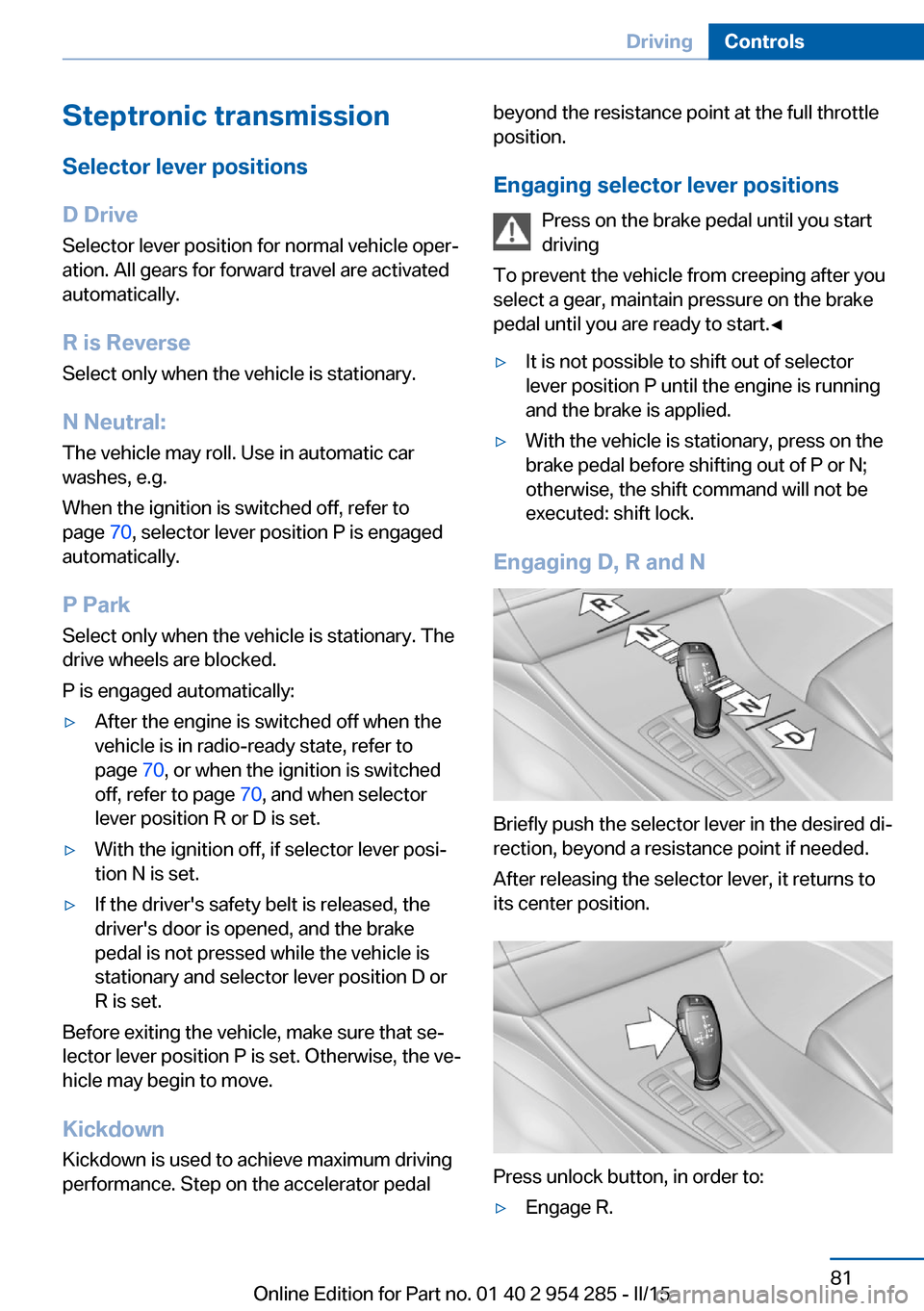
Engaging D, R and N
Briefly push the selector lever in the desired di‐
rection, beyond a resistance point if needed.
After releasing the selector lever, it returns to
its center position.
Press unlock button, in order to:
▷Engage R.Seite 81DrivingControls81
Online Edition for Part no. 01 40 2 954 285 - II/15
Page 108 of 263
In tight curves, e.g., on mountainous roads or
when turning, an additional, corner-illuminating
lamp is switched on that lights up the inside of
the curve when the vehicle is moving below a
certain speed.
Activating Position of switch
with the ignition
switched on.
To avoid blinding oncoming traffic, the Adap‐
tive Light Control does not swivel to the driv‐
er's side when the vehicle is at a standstill.
The turning lights are automatically switched
on depending on the steering angle or the use
of turn signals.
When driving in reverse, the turning lights may
be automatically switched on regardless of the
steering angle.
Self-leveling headlights The self-leveling headlights compensate for
acceleration and braking operations in order
not to blind the oncoming traffic and to achieve
optimum illumination of the roadway.
Malfunction A Check Control message is displayed.
Adaptive Light Control is malfunctioning or has
failed. Have the system checked as soon as
possible.
High-beam Assistant
The concept When the low beams are activated, this system
automatically switches the high beams on and
off or suppresses the light in the areas that
blind oncoming traffic. The procedure is con‐
trolled by a camera on the front of the interior
rearview mirror. The assistant ensures that the
high beams are activated whenever the traffic
situation allows. The driver can intervene at
any time and switch the high beams non and
off as usual.
Note Personal responsibility
The High-beam Assistant cannot serve
as a substitute for the driver's personal judg‐
ment of when to use the high beams. There‐
fore, manually reel off the high beams in situa‐
tions where required to avoid a safety risk.◀
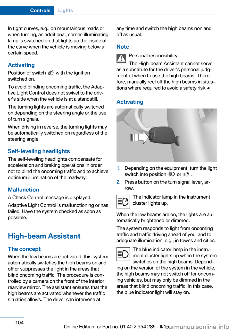
Activating1.Depending on the equipment, turn the light
switch into position
or .
2.Press button on the turn signal lever, ar‐
row.
The indicator lamp in the instrument
cluster lights up.
When the low beams are on, the lights are au‐
tomatically brightened or dimmed.
The system responds to light from oncoming
traffic and traffic driving ahead of you, and to
adequate illumination, e.g., in towns and cities.
The blue indicator lamp in the instru‐
ment cluster lights up when the system
switches on the high beams. Depend‐
ing on the version of the system in the vehicle, the high beams may not switch off for oncom‐
ing vehicles, but may only be dimmed in the
areas that blind oncoming traffic. In this case,
the blue indicator light will stay on.
Seite 104ControlsLights104
Online Edition for Part no. 01 40 2 954 285 - II/15
Page 164 of 263
▷Maximum distance to row of parked vehi‐
cles: 5 ft/1.5 m.
Suitable parking space
▷Gap between two objects with a minimum
length of approx. 5 ft/1.5 m.▷Min. length of gap between two objects:
your vehicle's length plus approx.
4 ft/1.2 m.▷Minimum depth: approx. 5 ft/1.5 m.
Regarding the parking procedure
▷Doors and trunk lid closed.▷Parking brake released.▷When parking in parking spaces on the
driver's side, the corresponding turn signal
must be set where applicable.
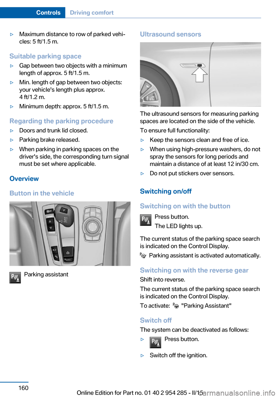
Overview
Button in the vehicle
Parking assistant
Ultrasound sensors
The ultrasound sensors for measuring parking
spaces are located on the side of the vehicle.
To ensure full functionality:
▷Keep the sensors clean and free of ice.▷When using high-pressure washers, do not
spray the sensors for long periods and
maintain a distance of at least 12 in/30 cm.▷Do not put stickers over sensors.
Switching on/off
Switching on with the button Press button.
The LED lights up.
The current status of the parking space search
is indicated on the Control Display.
Parking assistant is activated automatically.
Switching on with the reverse gear
Shift into reverse.
The current status of the parking space search
is indicated on the Control Display.
To activate:
"Parking Assistant"
Switch off
The system can be deactivated as follows:
▷Press button.▷Switch off the ignition.Seite 160ControlsDriving comfort160
Online Edition for Part no. 01 40 2 954 285 - II/15
Page 179 of 263
Cargo area
Cargo cover
Note Do not deposit heavy objects
Do not deposit heavy or hard objects on
the cargo cover. Otherwise, they may pose a
risk to occupants, such as during braking and
evasive maneuvers.◀
General information The cargo cover is in two parts.
It can be removed and stowed in the rear stor‐
age compartment when transporting bulky
items.
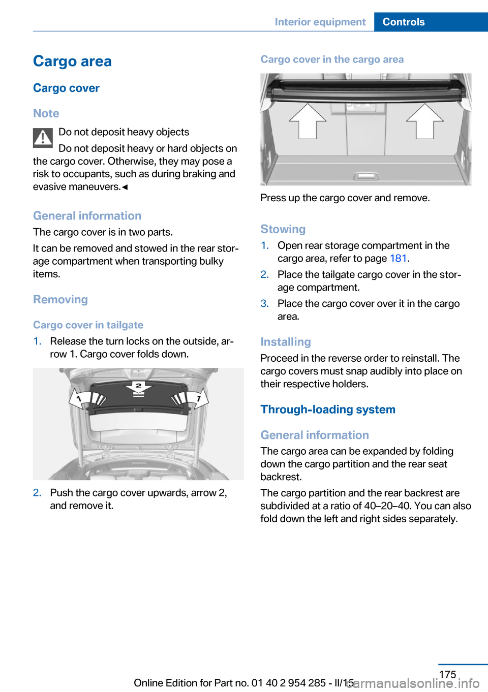
Removing Cargo cover in tailgate1.Release the turn locks on the outside, ar‐
row 1. Cargo cover folds down.2.Push the cargo cover upwards, arrow 2,
and remove it.Cargo cover in the cargo area
Press up the cargo cover and remove.
Stowing
1.Open rear storage compartment in the
cargo area, refer to page 181.2.Place the tailgate cargo cover in the stor‐
age compartment.3.Place the cargo cover over it in the cargo
area.
Installing
Proceed in the reverse order to reinstall. The
cargo covers must snap audibly into place on
their respective holders.
Through-loading system
General information
The cargo area can be expanded by folding
down the cargo partition and the rear seat
backrest.
The cargo partition and the rear backrest are
subdivided at a ratio of 40–20–40. You can also
fold down the left and right sides separately.
Seite 175Interior equipmentControls175
Online Edition for Part no. 01 40 2 954 285 - II/15
Page 229 of 263
Replacing componentsVehicle features and optionsThis chapter describes all standard, country-
specific and optional features offered with the
series. It also describes features that are not
necessarily available in your car, e. g., due to
the selected options or country versions. This
also applies to safety-related functions and
systems. The respectively applicable country
provisions must be observed when using the
respective features and systems.
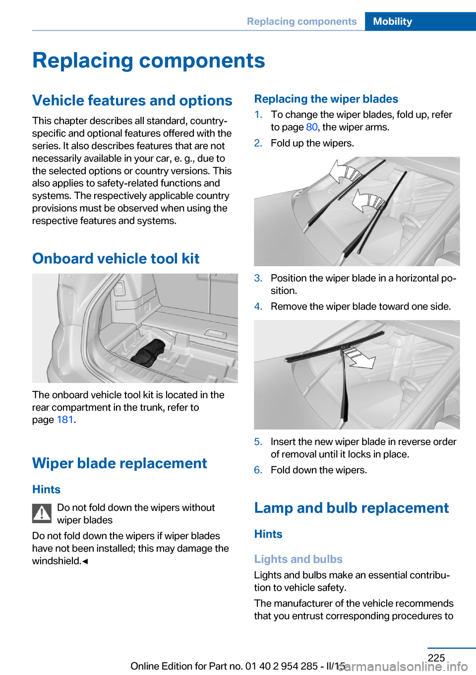
Onboard vehicle tool kit
The onboard vehicle tool kit is located in the
rear compartment in the trunk, refer to
page 181.
Wiper blade replacement Hints Do not fold down the wipers without
wiper blades
Do not fold down the wipers if wiper blades
have not been installed; this may damage the
windshield.◀
Replacing the wiper blades1.To change the wiper blades, fold up, refer
to page 80, the wiper arms.2.Fold up the wipers.3.Position the wiper blade in a horizontal po‐
sition.4.Remove the wiper blade toward one side.5.Insert the new wiper blade in reverse order
of removal until it locks in place.6.Fold down the wipers.
Lamp and bulb replacement
Hints
Lights and bulbs
Lights and bulbs make an essential contribu‐
tion to vehicle safety.
The manufacturer of the vehicle recommends
that you entrust corresponding procedures to
Seite 225Replacing componentsMobility225
Online Edition for Part no. 01 40 2 954 285 - II/15
Page 231 of 263
Hints
Because of the long life of these bulbs, the
likelihood of failure is very low. Switching the
lights on and off frequently shortens their life.
If a bulb fails, reel on the front fog lights and
continue the trip with great care. Comply with
local regulations.
Do not perform work/bulb replacement
on xenon headlights
Have any work on the xenon lighting system,
including bulb replacement, performed only by
a service center. Due to the high voltage
present in the system, there is a danger of fatal
injuries if work is carried out improperly.◀
For checking and adjusting headlamp aim,
please contact your BMW center.
Parking lights and roadside parking lamp,
turn signal lights
Follow general instructions, refer to page 225.
These lights feature LED technology.
Contact your service center in the event of a
malfunction.
Corner-illuminating lights
Follow general instructions, refer to page 225.
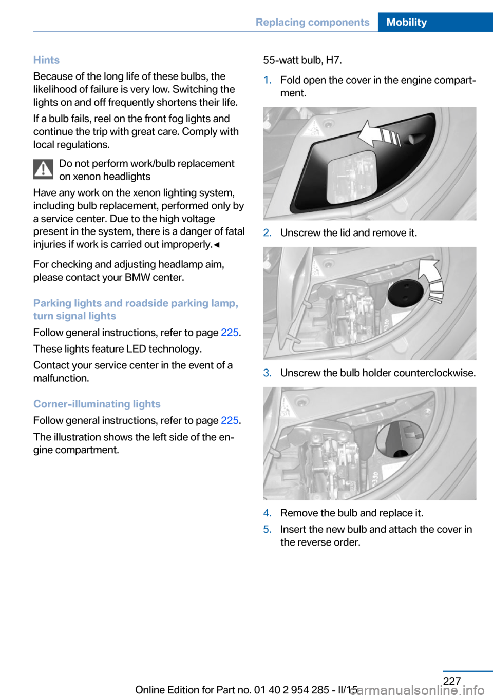
The illustration shows the left side of the en‐
gine compartment.55-watt bulb, H7.1.Fold open the cover in the engine compart‐
ment.2.Unscrew the lid and remove it.3.Unscrew the bulb holder counterclockwise.4.Remove the bulb and replace it.5.Insert the new bulb and attach the cover in
the reverse order.Seite 227Replacing componentsMobility227
Online Edition for Part no. 01 40 2 954 285 - II/15