2015 BMW 5 SERIES GRAN TURISMO Rear door
[x] Cancel search: Rear doorPage 55 of 263
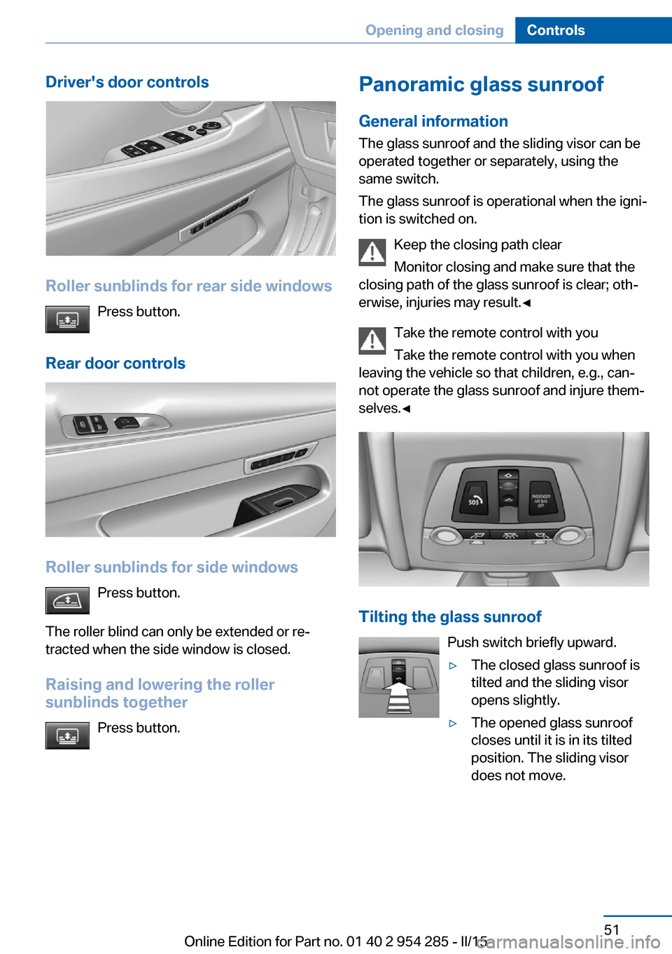
Driver's door controls
Roller sunblinds for rear side windowsPress button.
Rear door controls
Roller sunblinds for side windows Press button.
The roller blind can only be extended or re‐
tracted when the side window is closed.
Raising and lowering the roller
sunblinds together
Press button.
Panoramic glass sunroof
General information The glass sunroof and the sliding visor can be
operated together or separately, using the
same switch.
The glass sunroof is operational when the igni‐
tion is switched on.
Keep the closing path clear
Monitor closing and make sure that the
closing path of the glass sunroof is clear; oth‐
erwise, injuries may result.◀
Take the remote control with you
Take the remote control with you when
leaving the vehicle so that children, e.g., can‐
not operate the glass sunroof and injure them‐
selves.◀
Tilting the glass sunroof
Push switch briefly upward.
▷The closed glass sunroof is
tilted and the sliding visor
opens slightly.▷The opened glass sunroof
closes until it is in its tilted
position. The sliding visor
does not move.Seite 51Opening and closingControls51
Online Edition for Part no. 01 40 2 954 285 - II/15
Page 70 of 263
Transporting children safelyVehicle features and optionsThis chapter describes all standard, country-
specific and optional features offered with the
series. It also describes features that are not
necessarily available in your car, e. g., due tothe selected options or country versions. This
also applies to safety-related functions and
systems. The respectively applicable country
provisions must be observed when using the
respective features and systems.
The right place for children
Note
Children in the vehicle
Do not leave children unattended in the
vehicle; otherwise, they could endanger them‐
selves and other persons, e.g., by opening the
doors.◀
Children should always be in the rear Accident research shows that the safest place
for children is in the back seat.
Transporting children in the rear
Only transport children younger than
13 years of age or shorter than 5 ft/150 cm in
the rear in child restraint systems provided in
accordance with the age, weight and size of
the child; otherwise, there is an increased risk
of injury in an accident.
Children 13 years of age or older must wear a
safety belt as soon as a suitable child restraint
system can no longer be used due to their age,
weight and size.◀
Children on the front passenger seat
Should it ever be necessary to use a child re‐
straint system in the front passenger seat,
make sure that the front, knee and side airbags
on the front passenger side are deactivated.
Automatic deactivation of front-seat passen‐
ger airbags, refer to page 109.Note
Deactivating the front-seat passenger
airbags
If a child restraint system is used in the front
passenger seat, deactivate the front-seat pas‐
senger airbags; otherwise, there is an in‐
creased risk of injury to the child when the air‐
bags are activated, even with a child restraint
system.◀
Installing child restraint
systems
Hints Manufacturer's information for child re‐straint systems
To select, mount and use child restraint sys‐
tems, observe the information provided by the
system manufacturer; otherwise, the protec‐
tive effect can be lost.◀
Ensuring the stability of the child seat
When installing child restraint systems,
make sure that the child seat is securely fas‐
tened to the backrest of the seat. Angle and
headrest of the backrest might need to be ad‐
justed or possibly be removed. Make sure that
all backrests are securely locked. Otherwise
the stability of the child seat can be affected,
and there is an increased risk of injury becauseSeite 66ControlsTransporting children safely66
Online Edition for Part no. 01 40 2 954 285 - II/15
Page 73 of 263
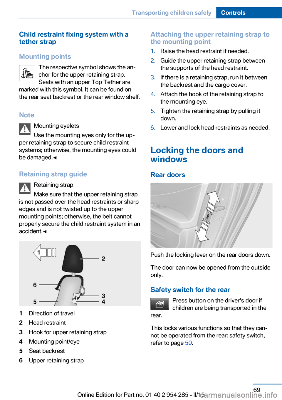
Child restraint fixing system with a
tether strap
Mounting points The respective symbol shows the an‐
chor for the upper retaining strap.
Seats with an upper Top Tether are
marked with this symbol. It can be found on
the rear seat backrest or the rear window shelf.
Note Mounting eyelets
Use the mounting eyes only for the up‐
per retaining strap to secure child restraint
systems; otherwise, the mounting eyes could
be damaged.◀
Retaining strap guide Retaining strap
Make sure that the upper retaining strap
is not passed over the head restraints or sharp
edges and is not twisted up to the upper
mounting points; otherwise, the belt cannot
properly secure the child restraint system in an
accident.◀1Direction of travel2Head restraint3Hook for upper retaining strap4Mounting point/eye5Seat backrest6Upper retaining strapAttaching the upper retaining strap to
the mounting point1.Raise the head restraint if needed.2.Guide the upper retaining strap between
the supports of the head restraint.3.If there is a retaining strap, run it between
the backrest and the cargo cover.4.Attach the hook of the retaining strap to
the mounting eye.5.Tighten the retaining strap by pulling it
down.6.Lower and lock head restraints as needed.
Locking the doors and
windows
Rear doors
Push the locking lever on the rear doors down.
The door can now be opened from the outside
only.
Safety switch for the rear Press button on the driver's door if
children are being transported in the
rear.
This locks various functions so that they can‐
not be operated from the rear: safety switch,
refer to page 50.
Seite 69Transporting children safelyControls69
Online Edition for Part no. 01 40 2 954 285 - II/15
Page 106 of 263
LightsVehicle features and optionsThis chapter describes all standard, country-
specific and optional features offered with the
series. It also describes features that are not
necessarily available in your car, e. g., due to
the selected options or country versions. This
also applies to safety-related functions and
systems. The respectively applicable country
provisions must be observed when using the
respective features and systems.
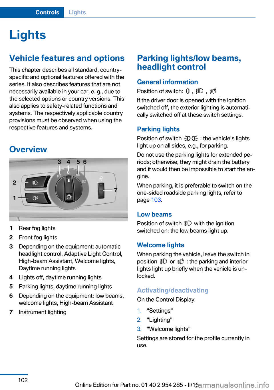
Overview1Rear fog lights2Front fog lights3Depending on the equipment: automatic
headlight control, Adaptive Light Control,
High-beam Assistant, Welcome lights,
Daytime running lights4Lights off, daytime running lights5Parking lights, daytime running lights6Depending on the equipment: low beams,
welcome lights, High-beam Assistant7Instrument lightingParking lights/low beams,
headlight control
General information
Position of switch:
, ,
If the driver door is opened with the ignition
switched off, the exterior lighting is automati‐
cally switched off at these switch settings.
Parking lights
Position of switch
: the vehicle's lights
light up on all sides, e.g., for parking.
Do not use the parking lights for extended pe‐
riods; otherwise, they might drain the battery
and it would then be impossible to start the en‐
gine.
When parking, it is preferable to switch on the
one-sided roadside parking lights, refer to
page 103.
Low beams Position of switch
with the ignition
switched on: the low beams light up.
Welcome lights
When parking the vehicle, leave the switch in
position
or : the parking and interior
lights light up briefly when the vehicle is un‐
locked.
Activating/deactivating
On the Control Display:
1."Settings"2."Lighting"3."Welcome lights"
Settings are stored for the profile currently in
use.
Seite 102ControlsLights102
Online Edition for Part no. 01 40 2 954 285 - II/15
Page 161 of 263
Switch the system back on if needed.
Display
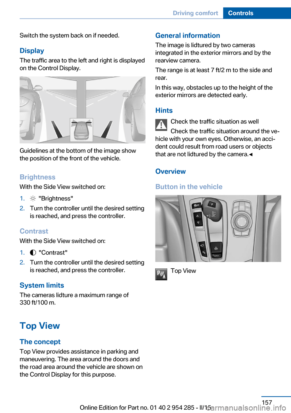
The traffic area to the left and right is displayed
on the Control Display.
Guidelines at the bottom of the image show
the position of the front of the vehicle.
Brightness With the Side View switched on:
1. "Brightness"2.Turn the controller until the desired setting
is reached, and press the controller.
Contrast
With the Side View switched on:
1. "Contrast"2.Turn the controller until the desired setting
is reached, and press the controller.
System limits
The cameras lidture a maximum range of
330 ft/100 m.
Top View
The concept Top View provides assistance in parking and
maneuvering. The area around the doors and
the road area around the vehicle are shown on
the Control Display for this purpose.
General information
The image is lidtured by two cameras
integrated in the exterior mirrors and by the
rearview camera.
The range is at least 7 ft/2 m to the side and
rear.
In this way, obstacles up to the height of the
exterior mirrors are detected early.
Hints Check the traffic situation as well
Check the traffic situation around the ve‐
hicle with your own eyes. Otherwise, an acci‐
dent could result from road users or objects
that are not lidtured by the camera.◀
Overview
Button in the vehicle
Top View
Seite 157Driving comfortControls157
Online Edition for Part no. 01 40 2 954 285 - II/15
Page 163 of 263
track line is continuously adjusted for the
steering wheel movement.
"Parking aid lines"
Turning circle and pathway lines are displayed.
System limits
Top View cannot be used in the following sit‐
uations:
▷With a door open.▷With the tailgate open.▷With an exterior mirror folded in.▷In poor light.
A Check Control message is displayed in some
of these situations.
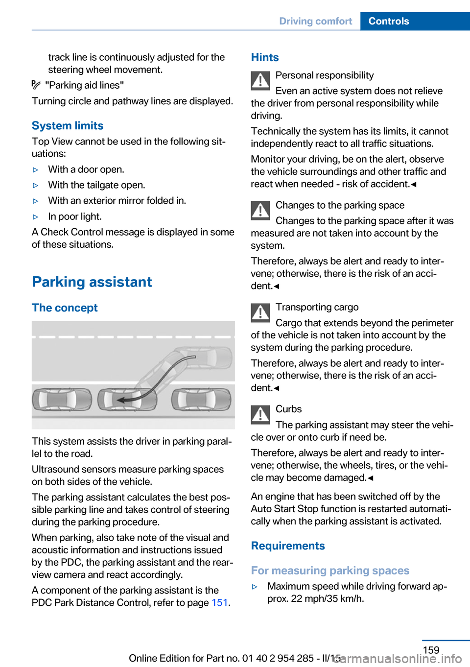
Parking assistant The concept
This system assists the driver in parking paral‐
lel to the road.
Ultrasound sensors measure parking spaces
on both sides of the vehicle.
The parking assistant calculates the best pos‐
sible parking line and takes control of steering
during the parking procedure.
When parking, also take note of the visual and
acoustic information and instructions issued
by the PDC, the parking assistant and the rear‐
view camera and react accordingly.
A component of the parking assistant is the
PDC Park Distance Control, refer to page 151.
Hints
Personal responsibility
Even an active system does not relieve
the driver from personal responsibility while
driving.
Technically the system has its limits, it cannot
independently react to all traffic situations.
Monitor your driving, be on the alert, observe
the vehicle surroundings and other traffic and
react when needed - risk of accident.◀
Changes to the parking space
Changes to the parking space after it was
measured are not taken into account by the system.
Therefore, always be alert and ready to inter‐
vene; otherwise, there is the risk of an acci‐
dent.◀
Transporting cargo
Cargo that extends beyond the perimeter
of the vehicle is not taken into account by the
system during the parking procedure.
Therefore, always be alert and ready to inter‐
vene; otherwise, there is the risk of an acci‐
dent.◀
Curbs
The parking assistant may steer the vehi‐
cle over or onto curb if need be.
Therefore, always be alert and ready to inter‐
vene; otherwise, the wheels, tires, or the vehi‐
cle may become damaged.◀
An engine that has been switched off by the
Auto Start Stop function is restarted automati‐
cally when the parking assistant is activated.
Requirements
For measuring parking spaces▷Maximum speed while driving forward ap‐
prox. 22 mph/35 km/h.Seite 159Driving comfortControls159
Online Edition for Part no. 01 40 2 954 285 - II/15
Page 174 of 263
Interior equipmentVehicle features and optionsThis chapter describes all standard, country-
specific and optional features offered with the
series. It also describes features that are not
necessarily available in your car, e. g., due to
the selected options or country versions. This
also applies to safety-related functions and
systems. The respectively applicable country
provisions must be observed when using the
respective features and systems.
Universal Integrated Remote Control
The concept The universal garage door opener can operate
up to 3 functions of remote-controlled sys‐
tems such as garage door drives or lighting
systems. The universal garage door opener re‐
places up to 3 different hand-held transmitters.
To operate the remote control, the buttons on
the interior rearview mirror must be program‐
med with the desired functions. The hand-held
transmitter for the particular system is required
in order to program the remote control.
During programming
During programming and before activat‐
ing a device using the universal garage door
opener, ensure that there are no people, ani‐
mals or objects in the area of the remote-con‐
trolled device; otherwise, there is a risk of in‐
jury or damage.
Also follow the safety instructions of the hand-
held transmitter.◀
Before selling the vehicle, delete the stored
functions for the sake of security.Compatibility
If this symbol is printed on the packag‐
ing or in the instructions of the system
to be controlled, the system is gener‐
ally compatible with the universal garage door opener.
If you have any questions, please contact:▷Your service center.▷www.homelink.com on the Internet.
HomeLink is a registered trademark of Gentex
Corporation.
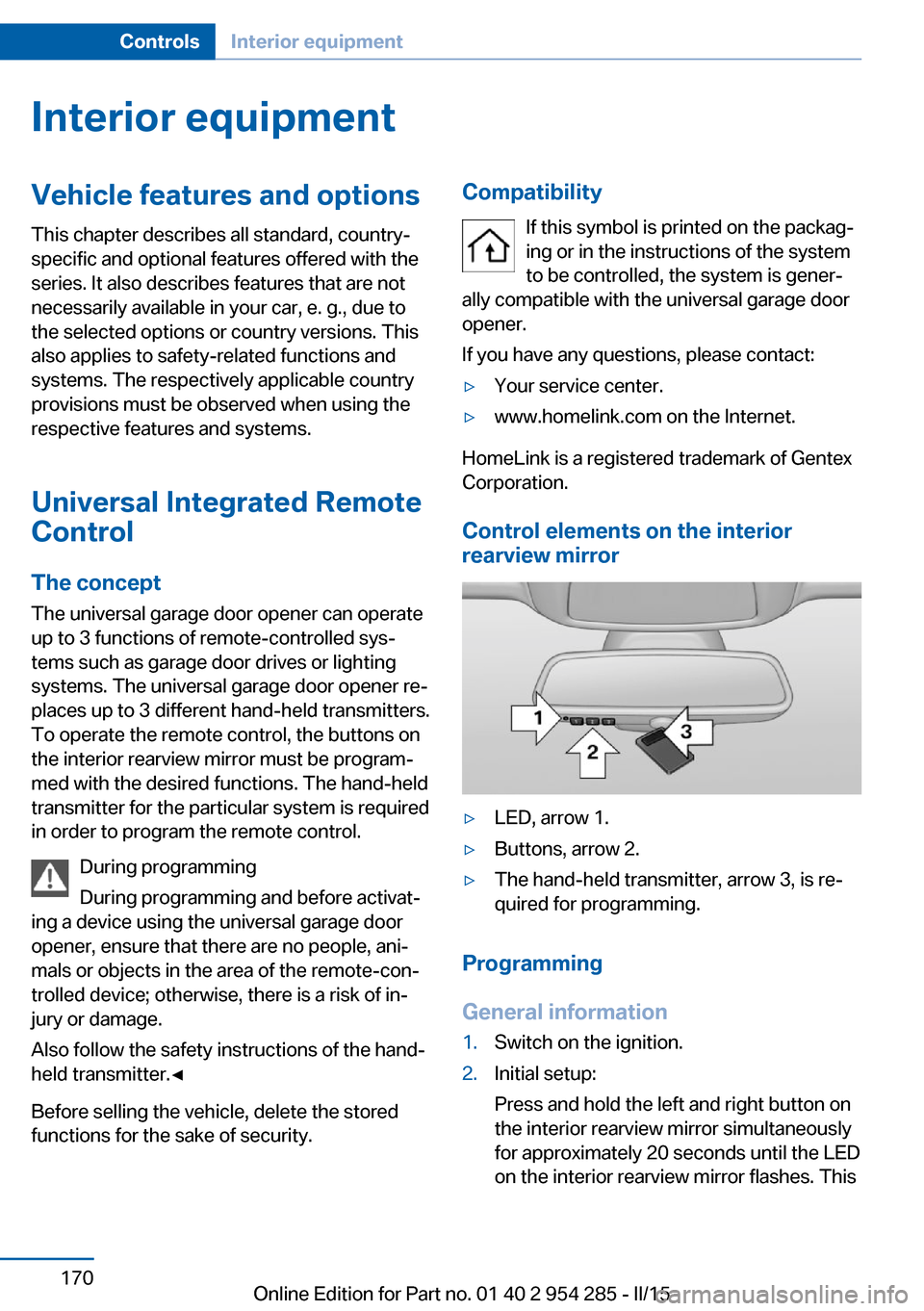
Control elements on the interior
rearview mirror
▷LED, arrow 1.▷Buttons, arrow 2.▷The hand-held transmitter, arrow 3, is re‐
quired for programming.
Programming
General information
1.Switch on the ignition.2.Initial setup:
Press and hold the left and right button on
the interior rearview mirror simultaneously
for approximately 20 seconds until the LED
on the interior rearview mirror flashes. ThisSeite 170ControlsInterior equipment170
Online Edition for Part no. 01 40 2 954 285 - II/15
Page 175 of 263
erases all programming of the buttons on
the interior rearview mirror.3.Hold the hand-held transmitter for the sys‐
tem to be controlled approx. 1 to 3 in/2.5 to
8 cm away from the buttons of the interior
rearview mirror. The required distance de‐
pends on the manual transmitter.4.Simultaneously press and hold the button
of the desired function on the hand-held
transmitter and the button to be program‐
med on the interior rearview mirror. The
LED on the interior rearview mirror will be‐
gin flashing slowly.5.Release both buttons as soon as the LED
flashes more rapidly. The LED flashing
faster indicates that the button on the inte‐
rior rearview mirror has been programmed.
If the LED does not flash faster after at
least 60 seconds, change the distance be‐
tween the interior rearview mirror and the
hand-held transmitter and repeat the step.
Several more attempts at different distan‐
ces may be necessary. Wait at least
15 seconds between attempts.
Canada: if programming with the hand-
held transmitter was interrupted, hold
down the interior rearview mirror button
and repeatedly press and release the
hand-held transmitter button for 2 sec‐
onds.6.To program other functions on other but‐
tons, repeat steps 3 to 5.
The systems can be controlled using the inte‐
rior rearview mirror buttons.
Special feature of the alternating-
code wireless system
If you are unable to operate the system after
repeated programming, please check if the
system to be controlled features an alternat‐
ing-code system.
Read the system's operating manual, or press
the programmed button on the interior rear‐
view mirror longer. If the LED on the interior
rearview mirror starts flashing rapidly and then
stays lit constantly for 2 seconds, the system
features an alternating-code system. Flashing
and continuous illumination of the LED will re‐
peat for approximately 20 seconds.
For systems with an alternating-code system,
the universal garage door opener and the sys‐
tem also have to be synchronized.
Please read the operating manual to find out how to synchronize the system.
Synchronizing is easier with the aid of a sec‐
ond person.
To synchronize:1.Park the vehicle within range of the re‐
mote-controlled system.2.Program the relevant button on the interior
rearview mirror as described.3.Locate and press the synchronizing button
on the system being programmed. You
have approx. 30 seconds for the next step.4.Hold down the programmed button on the
interior rearview mirror for approximately
3 seconds and then release it. If necessary,
repeat this step up to three times in order
to finish synchronization. Once synchroni‐
zation is complete, the programmed func‐
tion will be carried out.
Reprogramming individual buttons
1.Switch on the ignition.2.Press and hold the interior rearview mirror
button to be programmed.3.As soon as the interior rearview mirror LED
starts flashing slowly, hold the hand-held
transmitter for the system to be controlled
approx. 1 to 3 in/2.5 to 8 cm away from the
buttons of the interior rearview mirror. The
required distance depends on the manual
transmitter.Seite 171Interior equipmentControls171
Online Edition for Part no. 01 40 2 954 285 - II/15