2015 BMW 3 SERIES SPORTS WAGON Wheels and tires
[x] Cancel search: Wheels and tiresPage 204 of 255
into the tires, which seals the damage from the
inside.
The compressor can be used to check the tire
inflation pressure.
Hints▷Follow the instructions on using the Mobi‐
lity System found on the compressor and
sealant container.▷Use of the Mobility System may be ineffec‐
tive if the tire puncture measures approx.
1/8 in/4 mm or more.▷Contact the nearest service center if the
tire cannot be made drivable.▷If possible, do not remove foreign bodies
that have penetrated the tire.▷Pull the speed limit sticker off the sealant
container and apply it to the steering
wheel.▷The use of a sealant can damage the TPM
wheel electronics. In this case, have the
electronics checked at the next opportu‐
nity and have them replaced if needed.
Enclosed areas
Do not let the engine run in enclosed
areas, since breathing in exhaust fumes may
lead to loss of consciousness and death. The
exhaust gases contain carbon monoxide, an
odorless and colorless but highly toxic gas.◀
Storage The Mobility System is located under the
cargo floor panel.
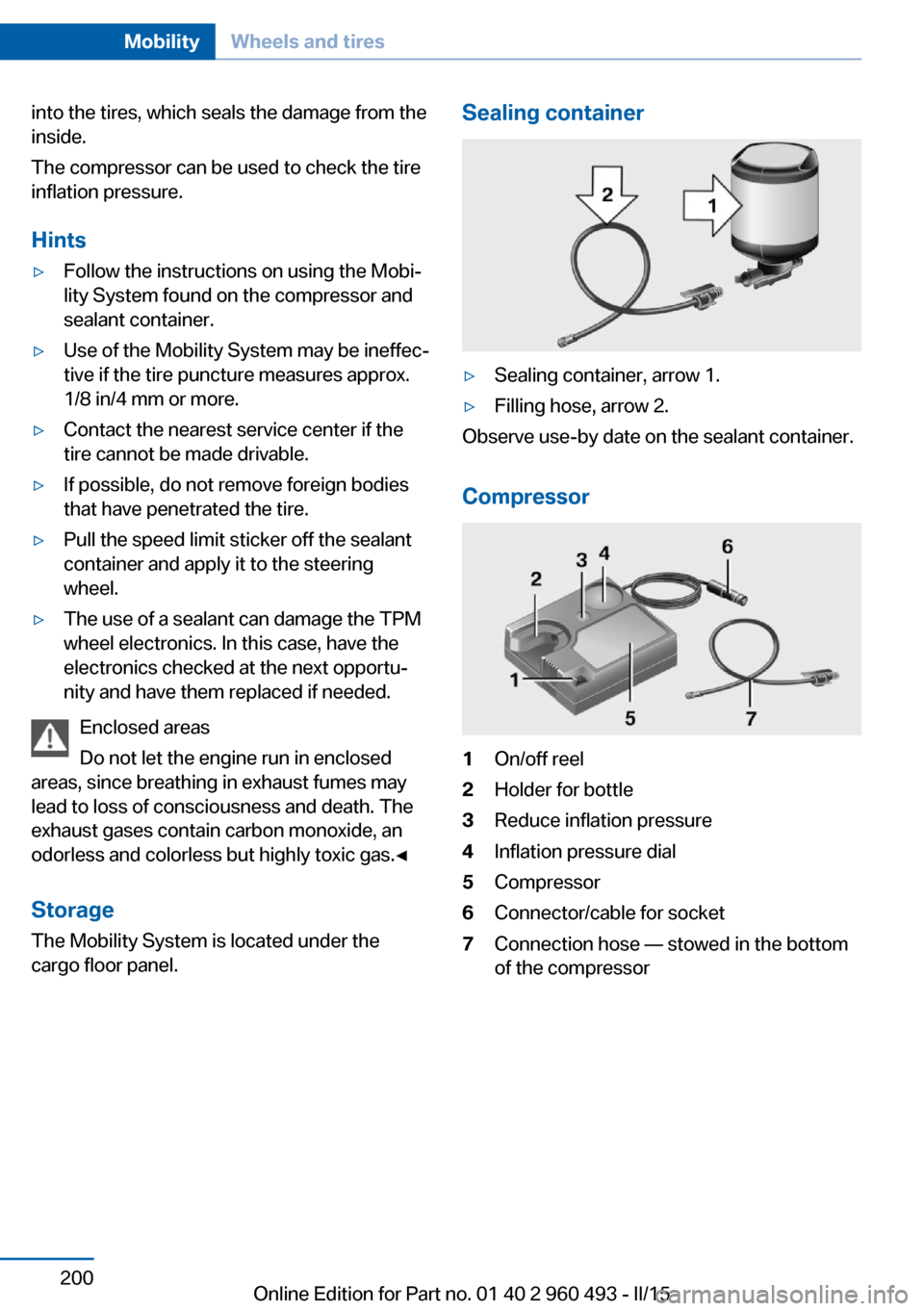
Sealing container▷Sealing container, arrow 1.▷Filling hose, arrow 2.
Observe use-by date on the sealant container.
Compressor
1On/off reel2Holder for bottle3Reduce inflation pressure4Inflation pressure dial5Compressor6Connector/cable for socket7Connection hose — stowed in the bottom
of the compressorSeite 200MobilityWheels and tires200
Online Edition for Part no. 01 40 2 960 493 - II/15
Page 205 of 255
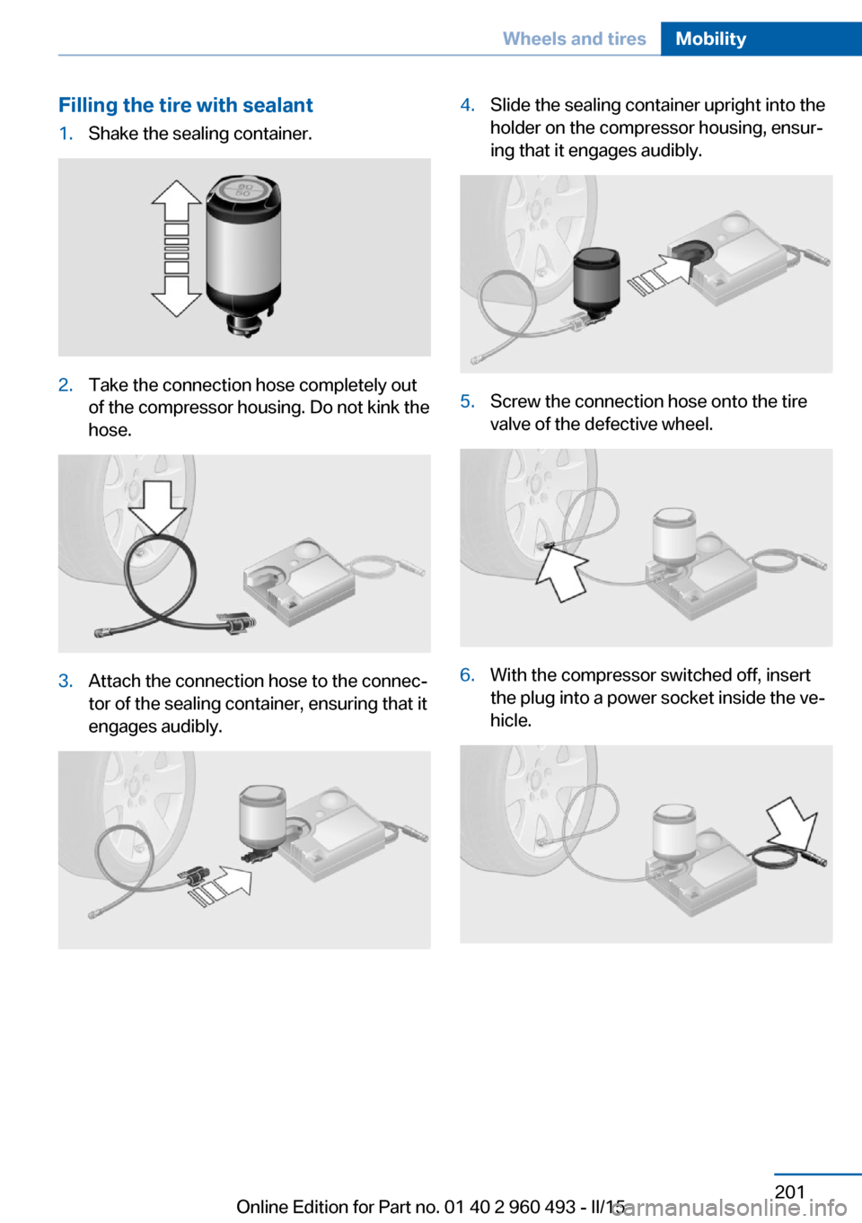
Filling the tire with sealant1.Shake the sealing container.2.Take the connection hose completely out
of the compressor housing. Do not kink the
hose.3.Attach the connection hose to the connec‐
tor of the sealing container, ensuring that it
engages audibly.4.Slide the sealing container upright into the
holder on the compressor housing, ensur‐
ing that it engages audibly.5.Screw the connection hose onto the tire
valve of the defective wheel.6.With the compressor switched off, insert
the plug into a power socket inside the ve‐
hicle.Seite 201Wheels and tiresMobility201
Online Edition for Part no. 01 40 2 960 493 - II/15
Page 206 of 255
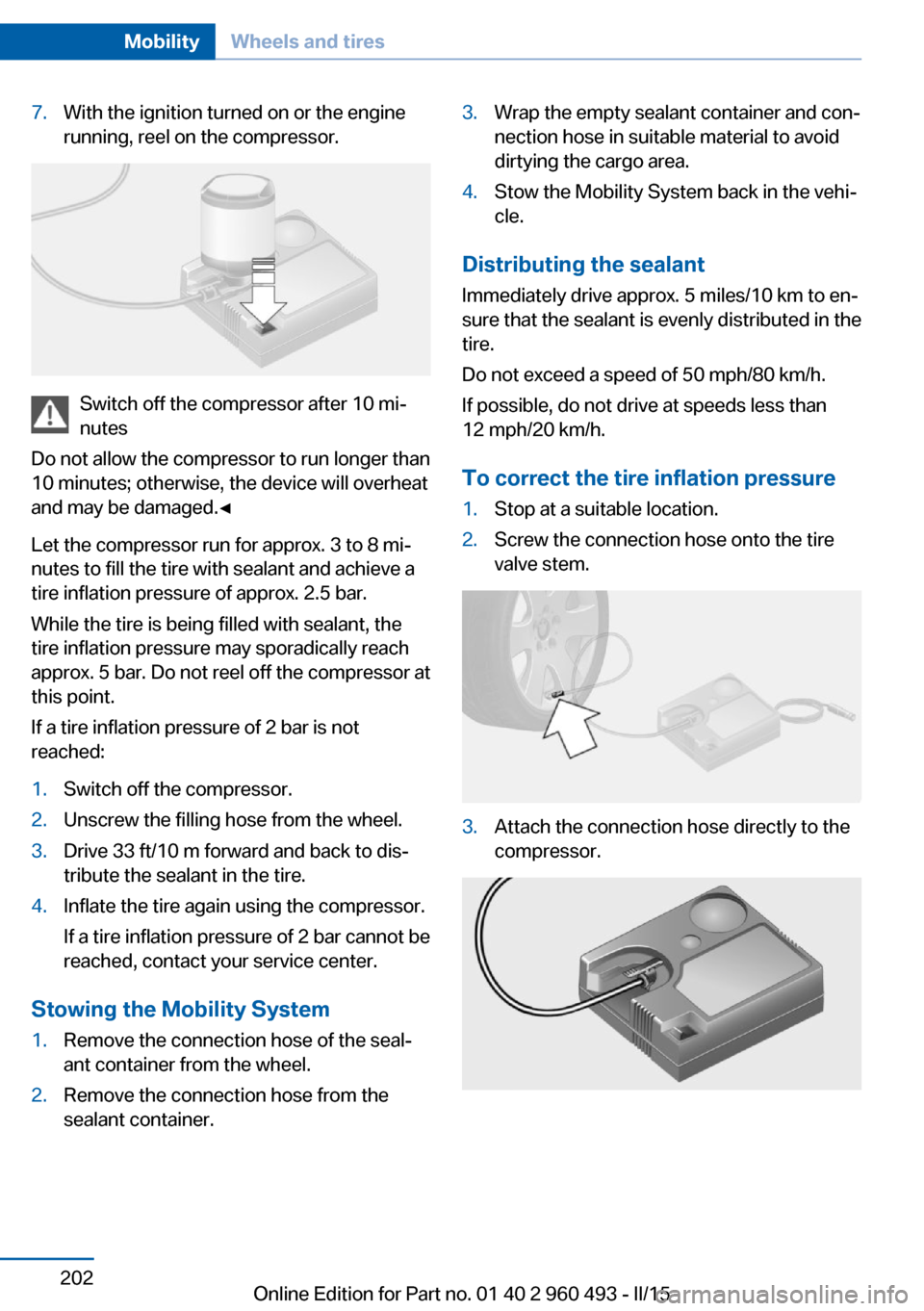
7.With the ignition turned on or the engine
running, reel on the compressor.
Switch off the compressor after 10 mi‐
nutes
Do not allow the compressor to run longer than
10 minutes; otherwise, the device will overheat
and may be damaged.◀
Let the compressor run for approx. 3 to 8 mi‐
nutes to fill the tire with sealant and achieve a
tire inflation pressure of approx. 2.5 bar.
While the tire is being filled with sealant, the
tire inflation pressure may sporadically reach
approx. 5 bar. Do not reel off the compressor at
this point.
If a tire inflation pressure of 2 bar is not
reached:
1.Switch off the compressor.2.Unscrew the filling hose from the wheel.3.Drive 33 ft/10 m forward and back to dis‐
tribute the sealant in the tire.4.Inflate the tire again using the compressor.
If a tire inflation pressure of 2 bar cannot be
reached, contact your service center.
Stowing the Mobility System
1.Remove the connection hose of the seal‐
ant container from the wheel.2.Remove the connection hose from the
sealant container.3.Wrap the empty sealant container and con‐
nection hose in suitable material to avoid
dirtying the cargo area.4.Stow the Mobility System back in the vehi‐
cle.
Distributing the sealant
Immediately drive approx. 5 miles/10 km to en‐
sure that the sealant is evenly distributed in the
tire.
Do not exceed a speed of 50 mph/80 km/h.
If possible, do not drive at speeds less than
12 mph/20 km/h.
To correct the tire inflation pressure
1.Stop at a suitable location.2.Screw the connection hose onto the tire
valve stem.3.Attach the connection hose directly to the
compressor.Seite 202MobilityWheels and tires202
Online Edition for Part no. 01 40 2 960 493 - II/15
Page 207 of 255
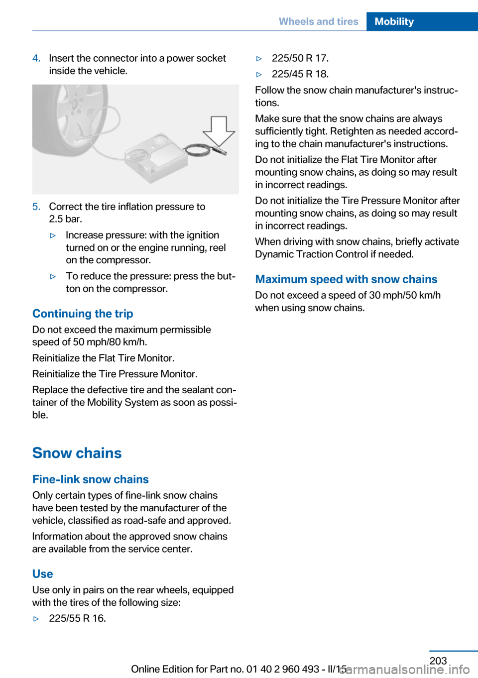
4.Insert the connector into a power socket
inside the vehicle.5.Correct the tire inflation pressure to
2.5 bar.▷Increase pressure: with the ignition
turned on or the engine running, reel
on the compressor.▷To reduce the pressure: press the but‐
ton on the compressor.
Continuing the trip
Do not exceed the maximum permissible
speed of 50 mph/80 km/h.
Reinitialize the Flat Tire Monitor.
Reinitialize the Tire Pressure Monitor.
Replace the defective tire and the sealant con‐
tainer of the Mobility System as soon as possi‐
ble.
Snow chains Fine-link snow chains
Only certain types of fine-link snow chains
have been tested by the manufacturer of the
vehicle, classified as road-safe and approved.
Information about the approved snow chains
are available from the service center.
Use
Use only in pairs on the rear wheels, equipped
with the tires of the following size:
▷225/55 R 16.▷225/50 R 17.▷225/45 R 18.
Follow the snow chain manufacturer's instruc‐
tions.
Make sure that the snow chains are always
sufficiently tight. Retighten as needed accord‐
ing to the chain manufacturer's instructions.
Do not initialize the Flat Tire Monitor after
mounting snow chains, as doing so may result
in incorrect readings.
Do not initialize the Tire Pressure Monitor after
mounting snow chains, as doing so may result
in incorrect readings.
When driving with snow chains, briefly activate
Dynamic Traction Control if needed.
Maximum speed with snow chains Do not exceed a speed of 30 mph/50 km/hwhen using snow chains.
Seite 203Wheels and tiresMobility203
Online Edition for Part no. 01 40 2 960 493 - II/15
Page 225 of 255
Changing wheels
Hints
When using run-flat tires or sealants, a tire
does not need to be changed immediately in
the event of pressure loss due to a flat tire.
Which is why no spare tire is available.
The tools for changing wheels are available as
accessories from your service center.
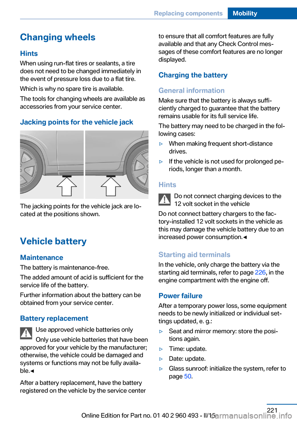
Jacking points for the vehicle jack
The jacking points for the vehicle jack are lo‐
cated at the positions shown.
Vehicle battery Maintenance
The battery is maintenance-free.
The added amount of acid is sufficient for the
service life of the battery.
Further information about the battery can be
obtained from your service center.
Battery replacement Use approved vehicle batteries only
Only use vehicle batteries that have been
approved for your vehicle by the manufacturer;
otherwise, the vehicle could be damaged and
systems or functions may not be fully availa‐
ble.◀
After a battery replacement, have the battery
registered on the vehicle by the service center
to ensure that all comfort features are fully
available and that any Check Control mes‐
sages of these comfort features are no longer
displayed.
Charging the battery
General information
Make sure that the battery is always suffi‐
ciently charged to guarantee that the battery
remains usable for its full service life.
The battery may need to be charged in the fol‐
lowing cases:▷When making frequent short-distance
drives.▷If the vehicle is not used for prolonged pe‐
riods, longer than a month.
Hints
Do not connect charging devices to the
12 volt socket in the vehicle
Do not connect battery chargers to the fac‐
tory-installed 12 volt sockets in the vehicle as
this may damage the vehicle battery due to an
increased power consumption.◀
Starting aid terminals
In the vehicle, only charge the battery via the
starting aid terminals, refer to page 226, in the
engine compartment with the engine off.
Power failure
After a temporary power loss, some equipment
needs to be newly initialized or individual set‐
tings updated, e. g.:
▷Seat and mirror memory: store the posi‐
tions again.▷Time: update.▷Date: update.▷Glass sunroof: initialize the system, refer to
page 50.Seite 221Replacing componentsMobility221
Online Edition for Part no. 01 40 2 960 493 - II/15
Page 234 of 255
CareVehicle features and optionsThis chapter describes all standard, country-
specific and optional features offered with the
series. It also describes features that are not
necessarily available in your car, e. g., due to
the selected options or country versions. This
also applies to safety-related functions and
systems. The respectively applicable country
provisions must be observed when using the
respective features and systems.
Car washes General information
Regularly remove foreign objects such as
leaves in the area below the windshield when
the hood is raised.
Wash your vehicle frequently, particularly in
winter. Intense soiling and road salt can dam‐
age the vehicle.
Hints Steam jets or high-pressure washers
When using steam jets or high-pressure
washers, hold them a sufficient distance away
and use a maximum temperature of
140 ℉/60 ℃.
If the vehicle has a glass sunroof, ensure that a
distance of at least 31.5 inches/80 cm is main‐
tained. Holding them too close or using exces‐
sively high pressures or temperatures can
cause damage or preliminary damage that may
then lead to long-term damage.
Follow the user's manual for the high-pressure
washer.◀Cleaning sensors/camera lenses with
high-pressure washers
When using high-pressure washers, do not
spray the sensors and camera lenses on the
outside of the vehicle for long periods and
maintain a distance of at least 12 in/30 cm.◀
Automatic car washes
Hints▷Give preference to cloth car washes or
those that use soft brushes in order to
avoid paint damage.▷Make sure that the wheels and tires are not
damaged by the transport mechanisms.▷Fold in the exterior mirrors; otherwise, they
may be damaged, depending on the width
of the vehicle.▷Deactivate the rain sensor, refer to
page 71, to avoid unintentional wiper acti‐
vation.▷In some cases, an unintentional alarm can
be triggered by the interior motion sensor
of the alarm system. Follow the instruc‐
tions on avoiding an unintentional alarm,
refer to page 47.
Guide rails in car washes
Avoid car washes with guide rails higher
than 4 in/10 cm; otherwise, the vehicle body
could be damaged.◀
Before driving into a car wash In order to ensure that the vehicle can roll in a
car wash, take the following steps:
Manual transmission:
1.Drive into the car wash.2.Shift to neutral.Seite 230MobilityCare230
Online Edition for Part no. 01 40 2 960 493 - II/15
Page 245 of 255
Bonus range, ECO PRO 178
Bottle holder, refer to Cu‐ pholders 165
Brake assistant 120
Brake discs, break-in 170
Brake force display 118
Brake lights, adaptive 118
Brake lights, brake force dis‐ play 118
Brake pads, break-in 170
Braking, hints 171
Breakdown assistance 224
Break-in 170
Brightness of Control Dis‐ play 91
Bulb replacement 213
Bulb replacement, front 214
Bulb replacement, halogen headlights 214
Bulb replacement, rear 218
Bulb replacement, xenon headlights 216
Bulbs and lights 213
Button, RES 128
Button, Start/Stop 65
Bypassing, refer to Jump- starting 225
C
California Proposition 65 Warning 7
Camera lenses, care 233
Camera, rearview cam‐ era 136
Camera, Side View 139
Camera, Top View 140
Can holder, refer to Cuphold‐ ers 165
Car battery 221
Car care products 231
Care, displays 233
Care, vehicle 231
Cargo 173
Cargo area 159
Cargo area, enlarging 160 Cargo area partition net 161
Cargo area, storage compart‐ ments 165
Cargo cover 159
Cargo, securing 174
Cargo straps, securing cargo 174
Car key, refer to Remote con‐ trol 34
Carpet, care 233
Car wash 230
Catalytic converter, refer to Hot exhaust system 171
CBS Condition Based Serv‐ ice 210
CD/Multimedia, see user's manual for Navigation, En‐
tertainment and Communi‐
cation
Center armrest 164
Center console 16
Central locking system 40
Central screen, refer to Con‐ trol Display 18
Changes, technical, refer to Safety 7
Changing parts 212
Changing wheels 221
Changing wheels/tires 198
Chassis number, see vehicle identification number 9
Check Control 79
Checking the engine oil level electronically 206
Checking the oil level elec‐ tronically 206
Children, seating position 61
Children, transporting safely 61
Child restraint fixing sys‐ tem 61
Child restraint fixing system LATCH 63
Child restraint fixing systems, mounting 61
Child safety locks 64 Child seat, mounting 61
Child seats 61
Chrome parts, care 232
Cigarette lighter 157
Cleaning displays 233
Climate control 146, 148
Clock 83
Closing/opening via door lock 39
Closing/opening with remote control 37
Closing the tailgate with no- touch activation 43
Clothes hooks 165
Coasting 180
Coasting with engine decou‐ pled, coasting 180
Coasting with idling en‐ gine 180
Cockpit 14
Cold starting, refer to Starting the engine 66
Combination reel, refer to Turn signals 70
Combination switch, refer to Wiper system 70
Comfort Access 42
COMFORT program, Dy‐ namic Driving Control 123
Compartments in the doors 164
Compass 155
Compressor 199
Computer, refer to On-board computer 87
Condensation on win‐ dows 151
Condensation under the vehi‐ cle 172
Condition Based Service CBS 210
Configuring driving pro‐ gram 124
Confirmation signal 45
ConnectedDrive, see user's manual for Navigation, En‐Seite 241Everything from A to ZReference241
Online Edition for Part no. 01 40 2 960 493 - II/15
Page 247 of 255
Emergency unlocking, trans‐mission lock 76
Energy Control 84
Energy recovery 84
Engine, automatic Start/Stop function 67
Engine, automatic switch- off 67
Engine compartment 204
Engine compartment, work‐ ing in 205
Engine coolant 209
Engine idling when driving, coasting 180
Engine oil 206
Engine oil, adding 207
Engine oil additives 208
Engine oil change 208
Engine oil filler neck 207
Engine oil temperature 82
Engine oil types, alterna‐ tive 208
Engine oil types, ap‐ proved 208
Engine start during malfunc‐ tion 35
Engine start, jump-start‐ ing 225
Engine start, refer to Starting the engine 66
Engine stop 67
Engine temperature 82
Entering a car wash 230
Equipment, interior 153
Error displays, see Check Control 79
ESP Electronic Stability Pro‐ gram, refer to DSC 120
Exchanging wheels/tires 198
Exhaust system 171
Exterior mirror, automatic dimming feature 59
Exterior mirrors 58
External start 225
External temperature dis‐ play 83 External temperature warn‐
ing 83
Eyes for securing cargo 174
F
Failure message, see Check Control 79
False alarm, refer to Uninten‐ tional alarm 47
Fan, refer to Air flow 147, 150
Filler neck for engine oil 207
Fine wood, care 232
First aid kit 225
Fitting for towing, see Tow fit‐ ting 228
Flat tire, changing wheels 221
Flat Tire Monitor FTM 105
Flat tire, Tire Pressure Moni‐ tor TPM 101
Flat tire, warning lamp 102, 105
Flooding 171
Floor carpet, care 233
Floor mats, care 233
Fogged up windows 147
Folding back rear seat back‐ rests 160
Fold-out position, wiper 72
Foot brake 171
Front airbags 98
Front-end collision warning with braking function 110
Front-end collision warning with City Braking func‐
tion 108
Front fog lights 96
Front fog lights, front, bulb re‐ placement 217
Front lights 214
front-seat passenger airbags, automatic deactivation 100
Front-seat passenger airbags, indicator lamp 100 FTM Flat Tire Monitor 105
Fuel 188
Fuel consumption, current 84
Fuel consumption, refer to Average fuel consump‐
tion 88
Fuel filler flap 186
Fuel gauge 82
Fuel lid 186
Fuel quality 188
Fuel recommendation 188
Fuel, tank capacity 238
Fuse 222
G
Garage door opener, refer to Universal Integrated Remote
Control 153
Gasoline 188
Gear change, Steptronic transmission 74
Gear shift indicator 85
General driving notes 170
Glare shield 157
Glass sunroof, refer to Panor‐ amic glass sunroof 48
Glove compartment 163
Gross vehicle weight, ap‐ proved 237
H
Handbrake, refer to parking brake 69
Hand-held transmitter, alter‐ nating code 154
Hazard warning flashers 224
Head airbags 98
Headlight control, auto‐ matic 94
Headlight courtesy delay fea‐ ture 94
Headlight flasher 70
Headlight glass 213
Headlights 214 Seite 243Everything from A to ZReference243
Online Edition for Part no. 01 40 2 960 493 - II/15