2015 BMW 3 SERIES SEDAN light
[x] Cancel search: lightPage 144 of 257
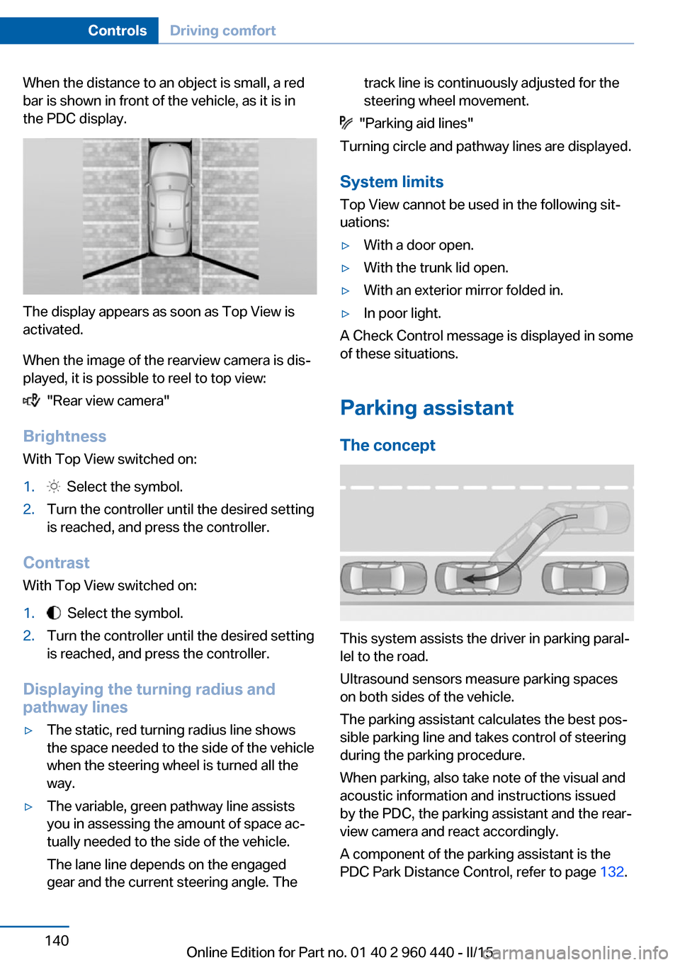
When the distance to an object is small, a red
bar is shown in front of the vehicle, as it is in
the PDC display.
The display appears as soon as Top View is
activated.
When the image of the rearview camera is dis‐
played, it is possible to reel to top view:
"Rear view camera"
Brightness
With Top View switched on:
1. Select the symbol.2.Turn the controller until the desired setting
is reached, and press the controller.
Contrast
With Top View switched on:
1. Select the symbol.2.Turn the controller until the desired setting
is reached, and press the controller.
Displaying the turning radius and
pathway lines
▷The static, red turning radius line shows
the space needed to the side of the vehicle
when the steering wheel is turned all the
way.▷The variable, green pathway line assists
you in assessing the amount of space ac‐
tually needed to the side of the vehicle.
The lane line depends on the engaged
gear and the current steering angle. Thetrack line is continuously adjusted for the
steering wheel movement.
"Parking aid lines"
Turning circle and pathway lines are displayed.
System limits
Top View cannot be used in the following sit‐
uations:
▷With a door open.▷With the trunk lid open.▷With an exterior mirror folded in.▷In poor light.
A Check Control message is displayed in some
of these situations.
Parking assistant The concept
This system assists the driver in parking paral‐
lel to the road.
Ultrasound sensors measure parking spaces
on both sides of the vehicle.
The parking assistant calculates the best pos‐
sible parking line and takes control of steering
during the parking procedure.
When parking, also take note of the visual and
acoustic information and instructions issued
by the PDC, the parking assistant and the rear‐
view camera and react accordingly.
A component of the parking assistant is the
PDC Park Distance Control, refer to page 132.
Seite 140ControlsDriving comfort140
Online Edition for Part no. 01 40 2 960 440 - II/15
Page 146 of 257

Ultrasound sensors
The ultrasound sensors for measuring parking
spaces are located on the side of the vehicle.
To ensure full functionality:
▷Keep the sensors clean and free of ice.▷When using high-pressure washers, do not
spray the sensors for long periods and
maintain a distance of at least 12 in/30 cm.▷Do not put stickers over sensors.
Switching on/off
Switching on with the button Press button.
The LED lights up.
The current status of the parking space search
is indicated on the Control Display.
Parking assistant is activated automatically.
Switching on with the reverse gear
Shift into reverse.
The current status of the parking space search
is indicated on the Control Display.
To activate:
"Parking Assistant"
Switch off
The system can be deactivated as follows:
▷Press button.▷Switch off the ignition.Display on the Control Display
System activated/deactivatedSymbolMeaning Gray: the system is not available.
White: the system is available but
not activated. The system is activated.
System status
▷Colored symbols, see arrows, on the side
of the vehicle illustrated. Parking assistant
is activated and search for parking space
active.▷Control Display shows suitable parking
spaces at the edge of the road next to the
vehicle symbol. When the parking assistant
is active, suitable parking spaces are high‐
lighted.▷The parking procedure is ac‐
tive. Steering control has
been taken over by system.▷Parking space search is always active
whenever the vehicle is moving forward
slow and straight, even if the system is de‐
activated. When the system is deactivated,
the displays on the Control Display are
shown in gray.Seite 142ControlsDriving comfort142
Online Edition for Part no. 01 40 2 960 440 - II/15
Page 155 of 257
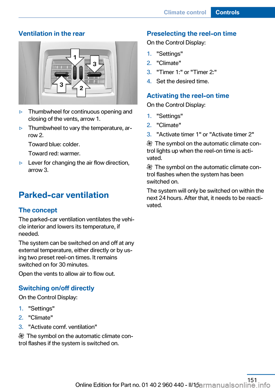
Ventilation in the rear▷Thumbwheel for continuous opening and
closing of the vents, arrow 1.▷Thumbwheel to vary the temperature, ar‐
row 2.
Toward blue: colder.
Toward red: warmer.▷Lever for changing the air flow direction,
arrow 3.
Parked-car ventilation
The concept The parked-car ventilation ventilates the vehi‐
cle interior and lowers its temperature, if
needed.
The system can be switched on and off at any
external temperature, either directly or by us‐
ing two preset reel-on times. It remains
switched on for 30 minutes.
Open the vents to allow air to flow out.
Switching on/off directly
On the Control Display:
1."Settings"2."Climate"3."Activate comf. ventilation"
The symbol on the automatic climate con‐
trol flashes if the system is switched on.
Preselecting the reel-on time
On the Control Display:1."Settings"2."Climate"3."Timer 1:" or "Timer 2:"4.Set the desired time.
Activating the reel-on time
On the Control Display:
1."Settings"2."Climate"3."Activate timer 1" or "Activate timer 2"
The symbol on the automatic climate con‐
trol lights up when the reel-on time is acti‐
vated.
The symbol on the automatic climate con‐
trol flashes when the system has been
switched on.
The system will only be switched on within the
next 24 hours. After that, it needs to be reacti‐
vated.
Seite 151Climate controlControls151
Online Edition for Part no. 01 40 2 960 440 - II/15
Page 156 of 257
Interior equipmentVehicle features and optionsThis chapter describes all standard, country-
specific and optional features offered with the
series. It also describes features that are not
necessarily available in your car, e. g., due to
the selected options or country versions. This
also applies to safety-related functions and
systems. The respectively applicable country
provisions must be observed when using the
respective features and systems.
Universal Integrated Remote Control
The concept The universal garage door opener can operate
up to 3 functions of remote-controlled sys‐
tems such as garage door drives or lighting
systems. The universal garage door opener re‐
places up to 3 different hand-held transmitters.
To operate the remote control, the buttons on
the interior rearview mirror must be program‐
med with the desired functions. The hand-held
transmitter for the particular system is required
in order to program the remote control.
During programming
During programming and before activat‐
ing a device using the universal garage door
opener, ensure that there are no people, ani‐
mals or objects in the area of the remote-con‐
trolled device; otherwise, there is a risk of in‐
jury or damage.
Also follow the safety instructions of the hand-
held transmitter.◀
Before selling the vehicle, delete the stored
functions for the sake of security.Compatibility
If this symbol is printed on the packag‐
ing or in the instructions of the system
to be controlled, the system is gener‐
ally compatible with the universal garage door opener.
If you have any questions, please contact:▷Your service center.▷www.homelink.com on the Internet.
HomeLink is a registered trademark of Gentex
Corporation.
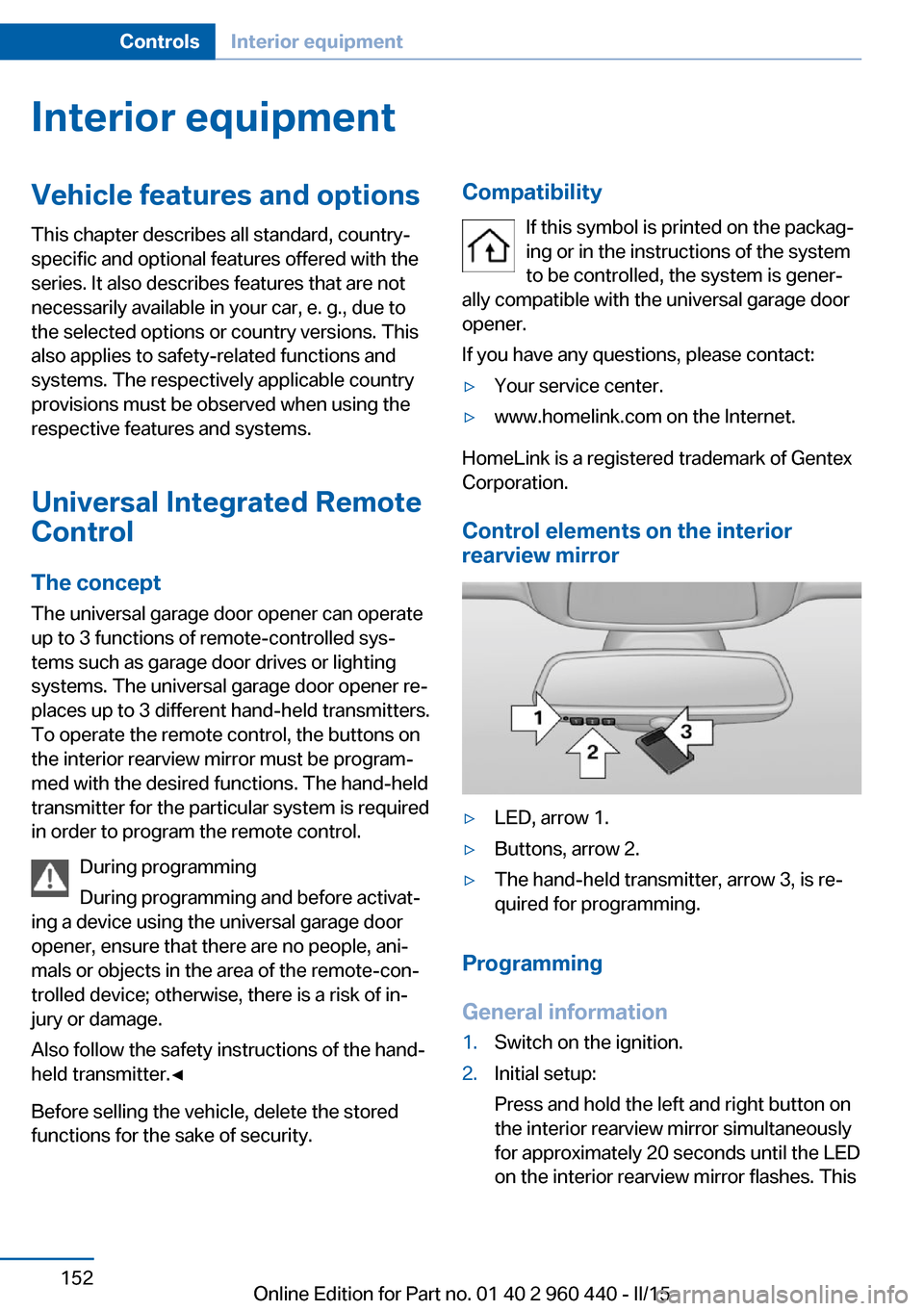
Control elements on the interior
rearview mirror
▷LED, arrow 1.▷Buttons, arrow 2.▷The hand-held transmitter, arrow 3, is re‐
quired for programming.
Programming
General information
1.Switch on the ignition.2.Initial setup:
Press and hold the left and right button on
the interior rearview mirror simultaneously
for approximately 20 seconds until the LED
on the interior rearview mirror flashes. ThisSeite 152ControlsInterior equipment152
Online Edition for Part no. 01 40 2 960 440 - II/15
Page 160 of 257

Settings are stored automatically after approxi‐
mately 10 seconds.
Sun visor
Glare shield Fold the sun visor down or up.
Vanity mirror A vanity mirror is located in the sun visor be‐
hind a cover. When the cover is opened, the
mirror lighting switches on.
Ashtray/cigarette lighterAshtray
Opening
Raise cover.
EmptyingTake out the insert.
Lighter Danger of burns
Only hold the hot lighter by its knob; oth‐
erwise, there is a danger of getting burned.
Switch off the ignition and take the remote
control with you when leaving the vehicle so
that children cannot use the lighter and burn
themselves.◀
Replace the cover after use
Reinsert the lighter or socket cover after
use, otherwise objects may get into the lighter
socket or fixture and cause a short circuit.◀
The lighter is located next to the ashtray.
Push in the lighter.
The lighter can be removed as
soon as it pops back out.
Connecting electrical devices
Hints Do not connect charging devices to the
12 volt socket in the vehicle
Do not connect battery chargers to the fac‐
tory-installed 12 volt sockets in the vehicle as
this may damage the vehicle battery due to an
increased power consumption.◀
Replace the cover after use
Reinsert the lighter or socket cover after
use, otherwise objects may get into the lighter
socket or fixture and cause a short circuit.◀
Sockets
General information
The lighter socket can be used as a socket for
electrical equipment while the engine is run‐ ning or when the ignition is switched on.
Seite 156ControlsInterior equipment156
Online Edition for Part no. 01 40 2 960 440 - II/15
Page 161 of 257

NoteThe total load of all sockets must not exceed
140 watts at 12 volts.
Do not damage the socket by using unsuitable
connectors.
Front center console
Raise the lid and remove the cover or cigarette
lighter.
Rear center console
Remove the cover.
In the trunk
The socket is located on the left side in the
trunk.
USB interface for data
transfer
The concept
Connection for importing and exporting data
on USB devices, e.g.:
▷Personal Profile settings, refer to page 35.▷Music collection.▷Importing Trips.
Hints
Observe the following when connecting:
▷Do not use force when plugging the con‐
nector into the USB interface.▷Do not connect devices such as fans or
lights to the USB interface.▷Do not connect USB hard drives.▷Do not use the USB interface for recharg‐
ing external devices.Seite 157Interior equipmentControls157
Online Edition for Part no. 01 40 2 960 440 - II/15
Page 163 of 257
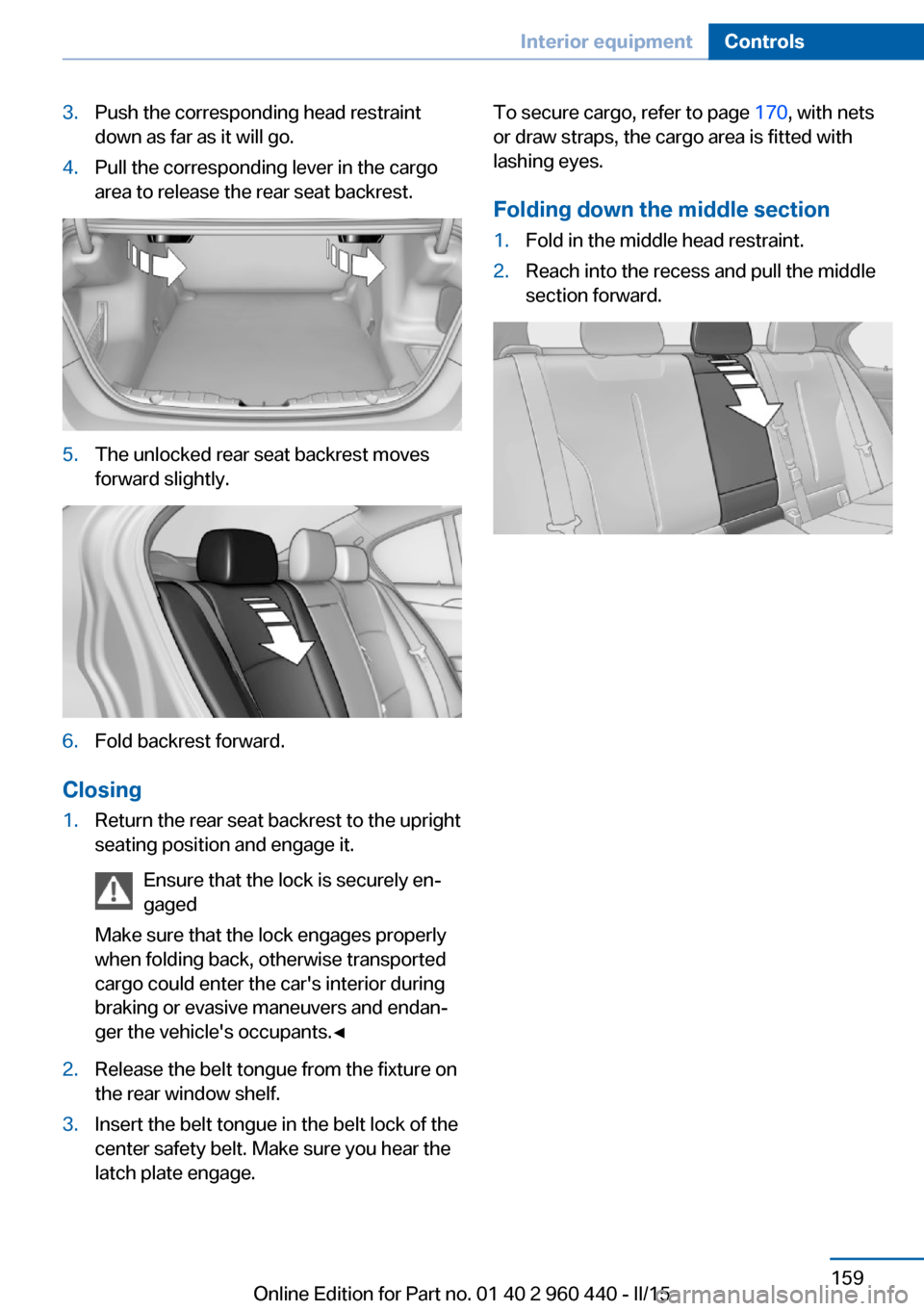
3.Push the corresponding head restraint
down as far as it will go.4.Pull the corresponding lever in the cargo
area to release the rear seat backrest.5.The unlocked rear seat backrest moves
forward slightly.6.Fold backrest forward.
Closing
1.Return the rear seat backrest to the upright
seating position and engage it.
Ensure that the lock is securely en‐
gaged
Make sure that the lock engages properly
when folding back, otherwise transported
cargo could enter the car's interior during
braking or evasive maneuvers and endan‐
ger the vehicle's occupants.◀2.Release the belt tongue from the fixture on
the rear window shelf.3.Insert the belt tongue in the belt lock of the
center safety belt. Make sure you hear the
latch plate engage.To secure cargo, refer to page 170, with nets
or draw straps, the cargo area is fitted with
lashing eyes.
Folding down the middle section1.Fold in the middle head restraint.2.Reach into the recess and pull the middle
section forward.Seite 159Interior equipmentControls159
Online Edition for Part no. 01 40 2 960 440 - II/15
Page 164 of 257
Storage compartmentsVehicle features and optionsThis chapter describes all standard, country-
specific and optional features offered with the
series. It also describes features that are not
necessarily available in your car, e. g., due to
the selected options or country versions. This
also applies to safety-related functions and
systems. The respectively applicable country
provisions must be observed when using the
respective features and systems.
Hints No loose objects in the car's interior
Do not stow any objects in the car's inte‐
rior without securing them; otherwise, they
may present a danger to occupants e.g., during
braking and evasive maneuvers.◀
Do not place anti-slip mats on the dash‐
board
Do not place anti-slip mats on the dashboard.
The mat materials could damage the dash‐
board.◀
Storage compartments The following storage compartments are avail‐
able in the vehicle interior:▷Glove compartment on the front passenger
side, refer to page 160.▷Glove compartment on the driver's side,
refer to page 161.▷Without Smoker's package: Front storage
compartment, in front of the cupholders,
refer to page 161.▷Storage compartment in the front center
armrest, refer to page 161.▷Compartments in the doors, refer to
page 161.▷Nets on the backrests of the front seats.▷Storage compartment in the rear center
console, refer to page 162.
Glove compartment
Front passenger side
Note Close the glove compartment again im‐
mediately
Close the glove compartment immediately af‐
ter use while driving; otherwise, injury may oc‐
cur during accidents.◀
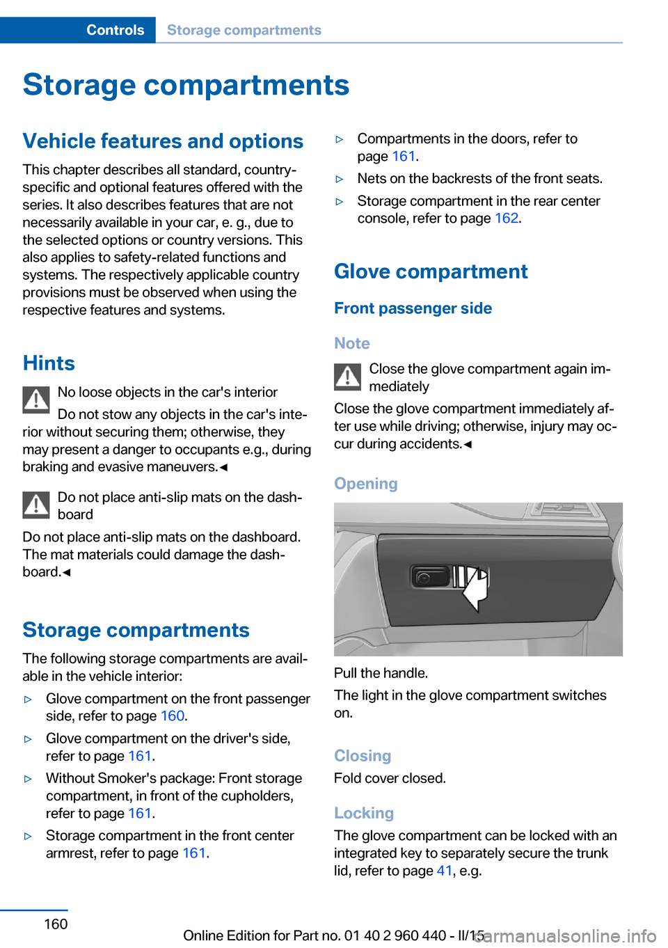
Opening
Pull the handle.
The light in the glove compartment switches
on.
ClosingFold cover closed.
Locking
The glove compartment can be locked with an
integrated key to separately secure the trunk
lid, refer to page 41, e.g.
Seite 160ControlsStorage compartments160
Online Edition for Part no. 01 40 2 960 440 - II/15