2015 BMW 3 SERIES GRAN TURISMO turn signal bulb
[x] Cancel search: turn signal bulbPage 73 of 251
Releasing
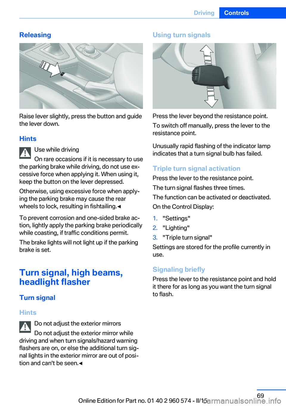
Raise lever slightly, press the button and guide
the lever down.
Hints Use while driving
On rare occasions if it is necessary to use
the parking brake while driving, do not use ex‐
cessive force when applying it. When using it,
keep the button on the lever depressed.
Otherwise, using excessive force when apply‐
ing the parking brake may cause the rear
wheels to lock, resulting in fishtailing.◀
To prevent corrosion and one-sided brake ac‐
tion, lightly apply the parking brake periodically
while coasting, if traffic conditions permit.
The brake lights will not light up if the parking
brake is set.
Turn signal, high beams,
headlight flasher
Turn signal
Hints Do not adjust the exterior mirrors
Do not adjust the exterior mirror while
driving and when turn signals/hazard warning
flashers are on, or else the additional turn sig‐
nal lights in the exterior mirror are out of posi‐
tion and can't be seen.◀
Using turn signals
Press the lever beyond the resistance point.
To switch off manually, press the lever to the
resistance point.
Unusually rapid flashing of the indicator lamp
indicates that a turn signal bulb has failed.
Triple turn signal activation Press the lever to the resistance point.
The turn signal flashes three times.
The function can be activated or deactivated.
On the Control Display:
1."Settings"2."Lighting"3."Triple turn signal"
Settings are stored for the profile currently in
use.
Signaling briefly
Press the lever to the resistance point and hold
it there for as long as you want the turn signal
to flash.
Seite 69DrivingControls69
Online Edition for Part no. 01 40 2 960 574 - II/15
Page 84 of 251
For more information, see Tire Pressure Moni‐
tor, refer to page 100.
Steering system Steering system in some cases defec‐
tive.
Have the steering system checked by
the service center.
Engine functions Have the vehicle checked by the serv‐ice center.
For additional information, refer to On-
board Diagnostics socket, refer to page 209.
Lane departure warning System is switched on and under cer‐
tain circumstances warns if a detected
lane is left without flashing beforehand.
For additional information, refer to Lane depar‐
ture warning, refer to page 114.
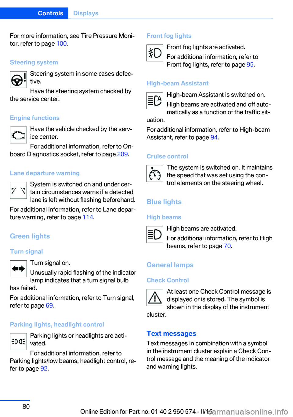
Green lights Turn signal Turn signal on.
Unusually rapid flashing of the indicator
lamp indicates that a turn signal bulb
has failed.
For additional information, refer to Turn signal,
refer to page 69.
Parking lights, headlight control Parking lights or headlights are acti‐
vated.
For additional information, refer to
Parking lights/low beams, headlight control, re‐
fer to page 92.Front fog lights
Front fog lights are activated.
For additional information, refer to
Front fog lights, refer to page 95.
High-beam Assistant High-beam Assistant is switched on.
High beams are activated and off auto‐
matically as a function of the traffic sit‐
uation.
For additional information, refer to High-beam
Assistant, refer to page 94.
Cruise control The system is switched on. It maintains
the speed that was set using the con‐
trol elements on the steering wheel.
Blue lights
High beams High beams are activated.
For additional information, refer to High
beams, refer to page 70.
General lamps
Check Control At least one Check Control message is
displayed or is stored. The symbol is
shown in the display of the instrument
cluster.
Text messagesText messages in combination with a symbol
in the instrument cluster explain a Check Con‐ trol message and the meaning of the indicator
and warning lights.Seite 80ControlsDisplays80
Online Edition for Part no. 01 40 2 960 574 - II/15
Page 215 of 251
Danger of burns
Only change bulbs when they are cool;
otherwise, there is a danger of getting
burned.◀
Working on the lighting system
When working on the lighting system,
you should always reel off the lights affected to
prevent short circuits.
To avoid possible injury or equipment damage
when replacing bulbs, observe any instructions
provided by the bulb manufacturer.◀
Do not perform work/bulb replacement
on xenon headlights
Have any work on the xenon lighting system,
including bulb replacement, performed only by
a service center. Due to the high voltage
present in the system, there is a danger of fatal
injuries if work is carried out improperly.◀
Do not touch the bulbs
Do not touch the glass of new bulbs with
your bare hands, as even minute amounts of
contamination will burn into the bulb's surface
and reduce its service life.
Use a clean tissue, cloth or something similar,
or hold the bulb by its base.◀
Light-emitting diodes (LEDs)
Some items of equipment use light-emitting
diodes installed behind a cover as a light
source.
These light-emitting diodes, which are related
to conventional lasers, are officially designated as Class 1 light-emitting diodes.
Do not remove the covers
Do not remove the covers, and never
stare into the unfiltered light for several hours;
otherwise, irritation of the retina could result.◀Headlight glass
Condensation can form on the inside of the ex‐
ternal lights in cool or humid weather. When
driving with the light switched on, the conden‐
sation evaporates after a short time. The head‐
light glass does not need to be changed.
If the headlights do not dim despite driving
with the light switched on, increasing humidity
forms, e. g. water droplets in the light, have the service center check this.
Headlight setting The headlight adjustments can be affected by
changing lights and bulbs. Have the head‐
lights' settings checked and corrected by serv‐
ice after a replacement.
Front lights, bulb replacement
Halogen headlights
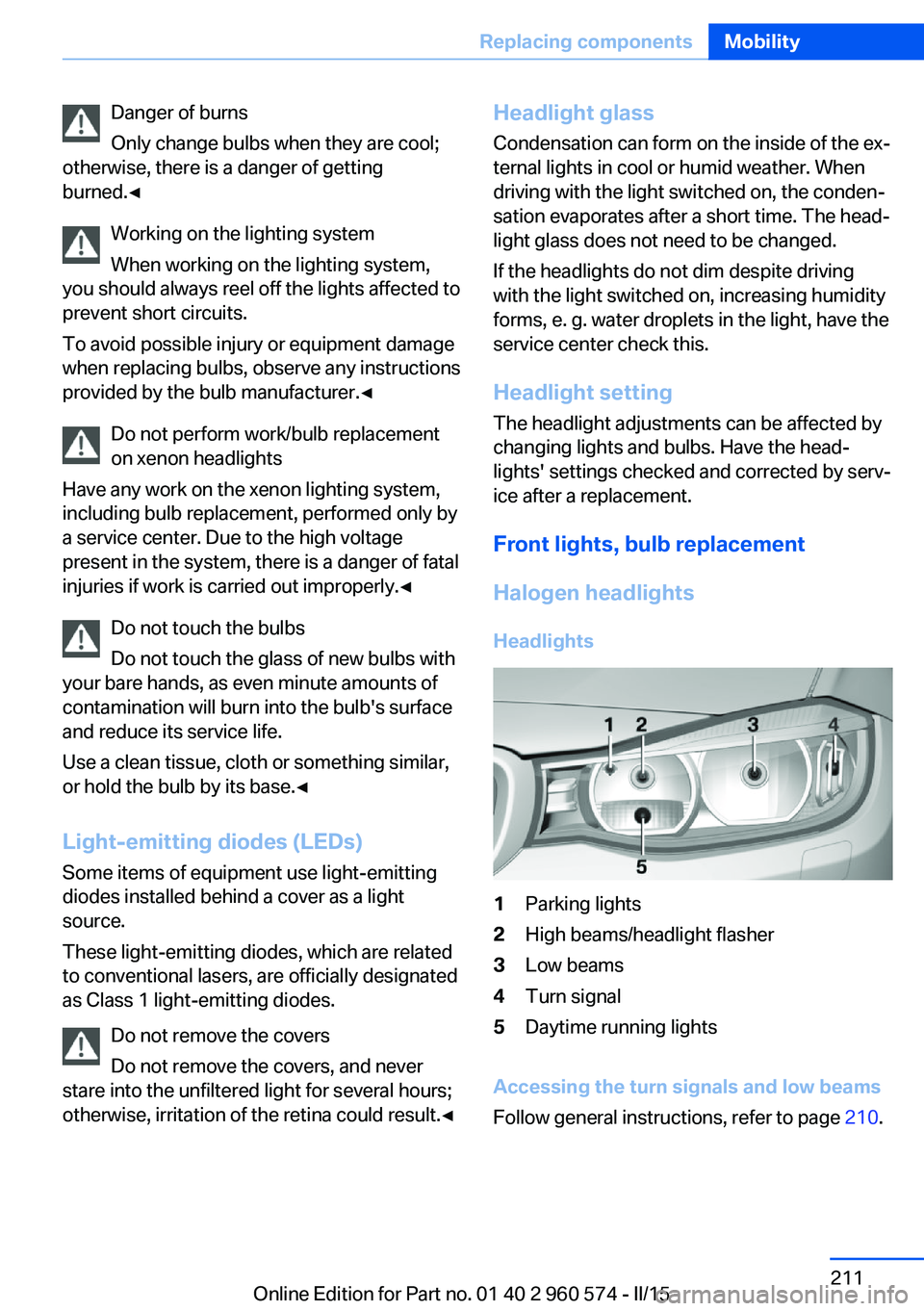
Headlights1Parking lights2High beams/headlight flasher3Low beams4Turn signal5Daytime running lights
Accessing the turn signals and low beams
Follow general instructions, refer to page 210.
Seite 211Replacing componentsMobility211
Online Edition for Part no. 01 40 2 960 574 - II/15
Page 216 of 251
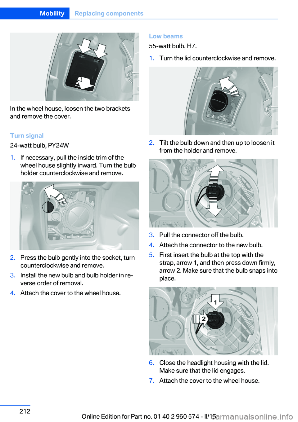
In the wheel house, loosen the two brackets
and remove the cover.
Turn signal
24-watt bulb, PY24W
1.If necessary, pull the inside trim of the
wheel house slightly inward. Turn the bulb
holder counterclockwise and remove.2.Press the bulb gently into the socket, turn
counterclockwise and remove.3.Install the new bulb and bulb holder in re‐
verse order of removal.4.Attach the cover to the wheel house.Low beams
55-watt bulb, H7.1.Turn the lid counterclockwise and remove.2.Tilt the bulb down and then up to loosen it
from the holder and remove.3.Pull the connector off the bulb.4.Attach the connector to the new bulb.5.First insert the bulb at the top with the
strap, arrow 1, and then press down firmly,
arrow 2. Make sure that the bulb snaps into
place.6.Close the headlight housing with the lid.
Make sure that the lid engages.7.Attach the cover to the wheel house.Seite 212MobilityReplacing components212
Online Edition for Part no. 01 40 2 960 574 - II/15
Page 218 of 251
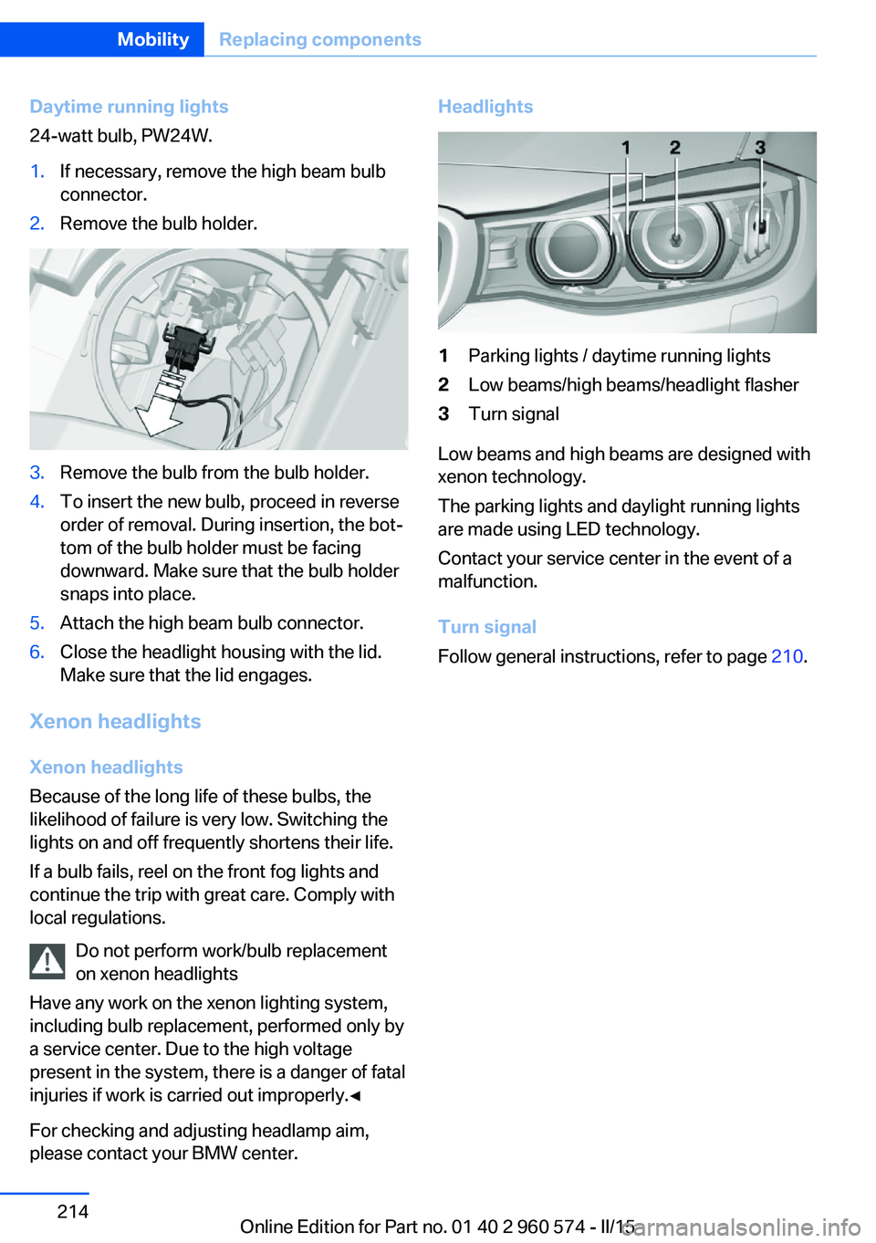
Daytime running lights
24-watt bulb, PW24W.1.If necessary, remove the high beam bulb
connector.2.Remove the bulb holder.3.Remove the bulb from the bulb holder.4.To insert the new bulb, proceed in reverse
order of removal. During insertion, the bot‐
tom of the bulb holder must be facing
downward. Make sure that the bulb holder
snaps into place.5.Attach the high beam bulb connector.6.Close the headlight housing with the lid.
Make sure that the lid engages.
Xenon headlights
Xenon headlights
Because of the long life of these bulbs, the
likelihood of failure is very low. Switching the
lights on and off frequently shortens their life.
If a bulb fails, reel on the front fog lights and
continue the trip with great care. Comply with
local regulations.
Do not perform work/bulb replacement
on xenon headlights
Have any work on the xenon lighting system,
including bulb replacement, performed only by
a service center. Due to the high voltage
present in the system, there is a danger of fatal
injuries if work is carried out improperly.◀
For checking and adjusting headlamp aim,
please contact your BMW center.
Headlights1Parking lights / daytime running lights2Low beams/high beams/headlight flasher3Turn signal
Low beams and high beams are designed with
xenon technology.
The parking lights and daylight running lights
are made using LED technology.
Contact your service center in the event of a
malfunction.
Turn signal
Follow general instructions, refer to page 210.
Seite 214MobilityReplacing components214
Online Edition for Part no. 01 40 2 960 574 - II/15
Page 219 of 251
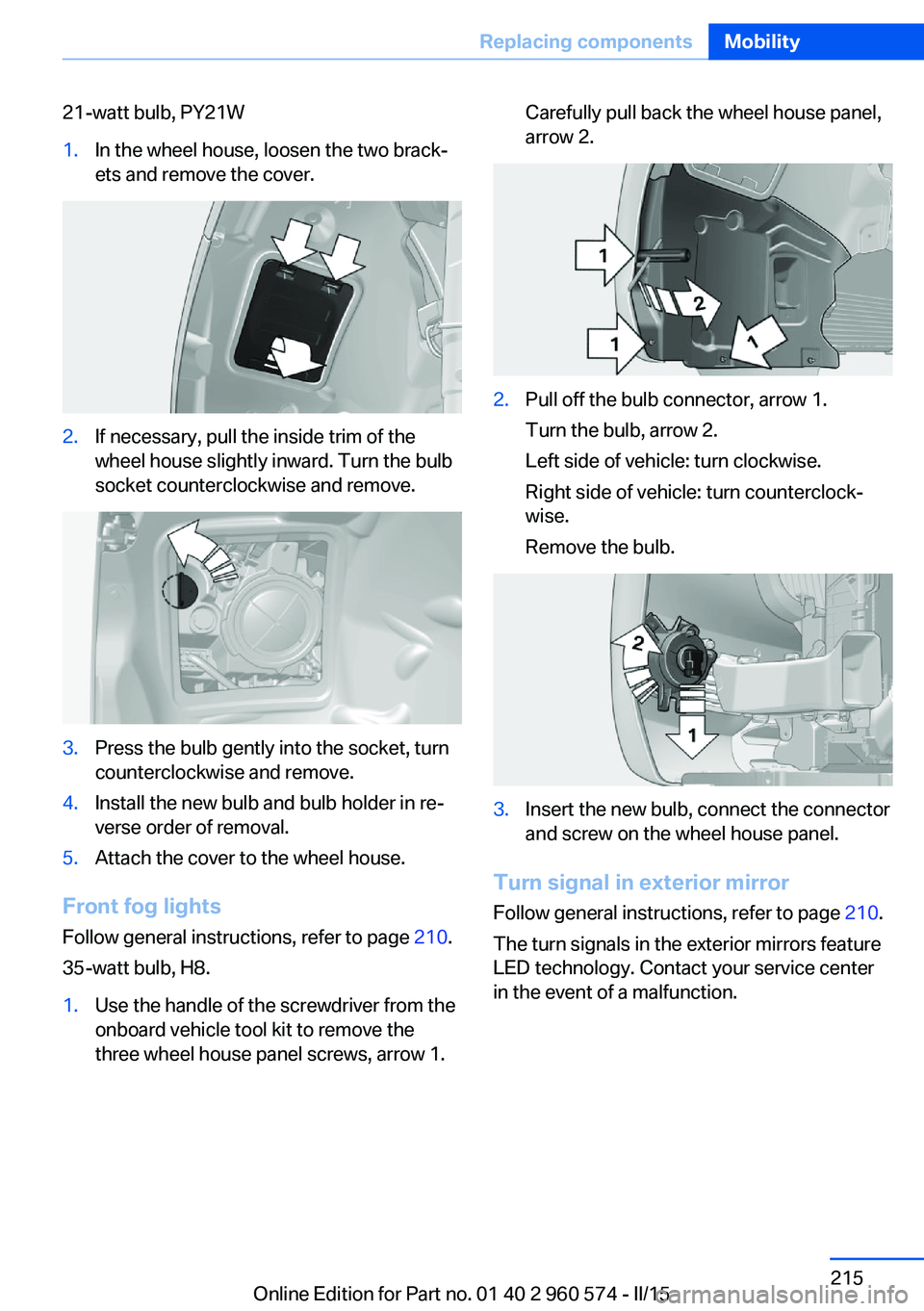
21-watt bulb, PY21W1.In the wheel house, loosen the two brack‐
ets and remove the cover.2.If necessary, pull the inside trim of the
wheel house slightly inward. Turn the bulb
socket counterclockwise and remove.3.Press the bulb gently into the socket, turn
counterclockwise and remove.4.Install the new bulb and bulb holder in re‐
verse order of removal.5.Attach the cover to the wheel house.
Front fog lights
Follow general instructions, refer to page 210.
35-watt bulb, H8.
1.Use the handle of the screwdriver from the
onboard vehicle tool kit to remove the
three wheel house panel screws, arrow 1.Carefully pull back the wheel house panel,
arrow 2.2.Pull off the bulb connector, arrow 1.
Turn the bulb, arrow 2.
Left side of vehicle: turn clockwise.
Right side of vehicle: turn counterclock‐
wise.
Remove the bulb.3.Insert the new bulb, connect the connector
and screw on the wheel house panel.
Turn signal in exterior mirror
Follow general instructions, refer to page 210.
The turn signals in the exterior mirrors feature
LED technology. Contact your service center
in the event of a malfunction.
Seite 215Replacing componentsMobility215
Online Edition for Part no. 01 40 2 960 574 - II/15
Page 220 of 251
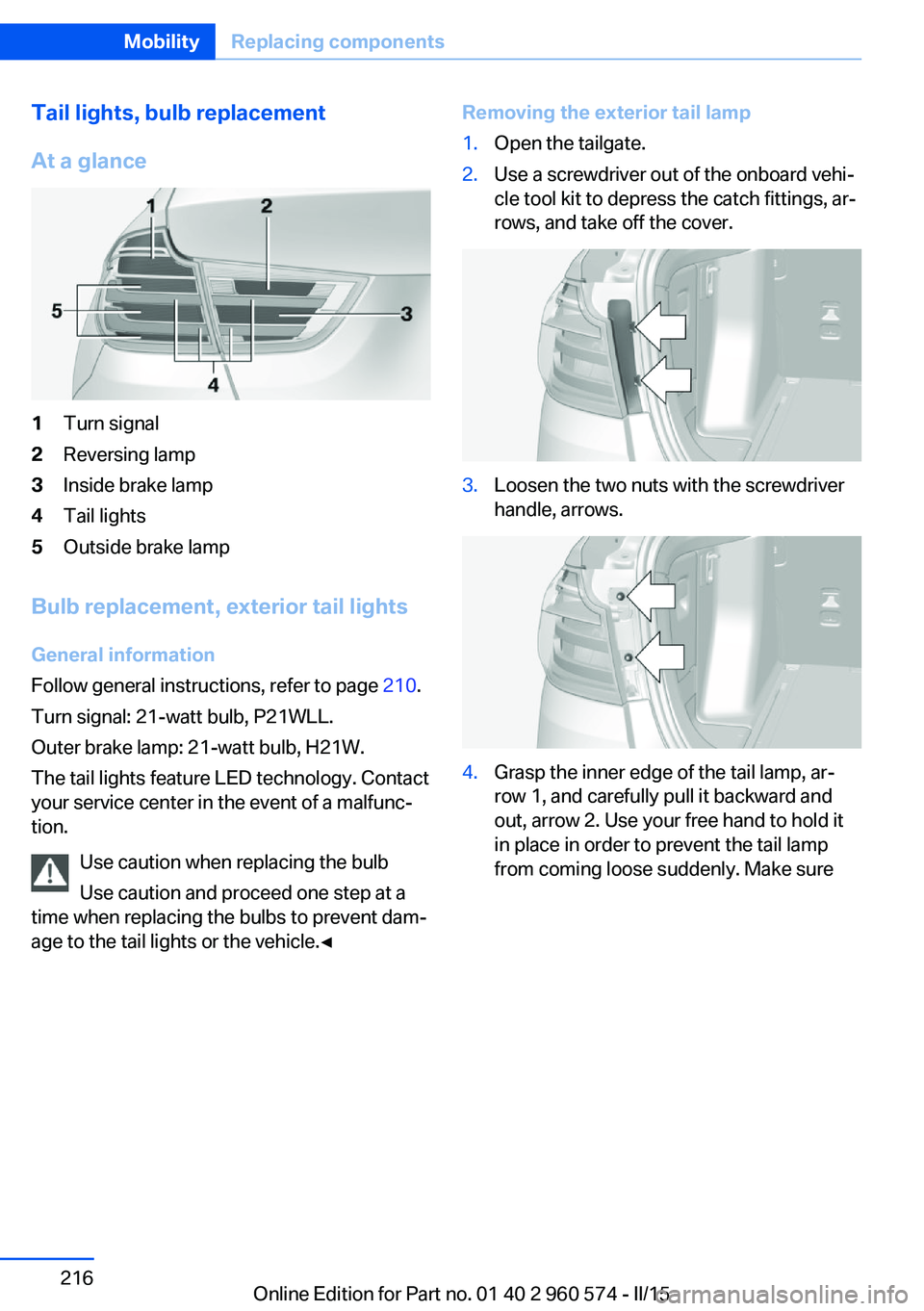
Tail lights, bulb replacement
At a glance1Turn signal2Reversing lamp3Inside brake lamp4Tail lights5Outside brake lamp
Bulb replacement, exterior tail lights General information
Follow general instructions, refer to page 210.
Turn signal: 21-watt bulb, P21WLL.
Outer brake lamp: 21-watt bulb, H21W.
The tail lights feature LED technology. Contact
your service center in the event of a malfunc‐
tion.
Use caution when replacing the bulb
Use caution and proceed one step at a
time when replacing the bulbs to prevent dam‐
age to the tail lights or the vehicle.◀
Removing the exterior tail lamp1.Open the tailgate.2.Use a screwdriver out of the onboard vehi‐
cle tool kit to depress the catch fittings, ar‐
rows, and take off the cover.3.Loosen the two nuts with the screwdriver
handle, arrows.4.Grasp the inner edge of the tail lamp, ar‐
row 1, and carefully pull it backward and
out, arrow 2. Use your free hand to hold it
in place in order to prevent the tail lamp
from coming loose suddenly. Make sureSeite 216MobilityReplacing components216
Online Edition for Part no. 01 40 2 960 574 - II/15
Page 241 of 251
Bonus range, ECO PRO 178
Bottle holder, refer to Cu‐ pholders 165
Brake assistant 119
Brake discs, break-in 170
Brake force display 118
Brake lights, adaptive 118
Brake lights, brake force dis‐ play 118
Brake pads, break-in 170
Braking, hints 171
Breakdown assistance 221
Break-in 170
Brightness of Control Dis‐ play 90
Bulb replacement 210
Bulb replacement, front 211
Bulb replacement, halogen headlights 211
Bulb replacement, rear 216
Bulb replacement, xenon headlights 214
Bulbs and lights 210
Button, RES 129
Button, Start/Stop 65
Bypassing, refer to Jump- starting 222
C
California Proposition 65 Warning 7
Camera lenses, care 229
Camera, rearview cam‐ era 137
Camera, Side View 140
Camera, Top View 141
Can holder, refer to Cuphold‐ ers 165
Car battery 218
Car care products 227
Care, displays 229
Care, vehicle 227
Cargo 173
Cargo area 160
Cargo area, enlarging 161 Cargo area, storage compart‐
ments 166
Cargo cover 160
Cargo position, rear seat backrest 162
Cargo, securing 174
Cargo straps, securing cargo 174
Car key, refer to Remote con‐ trol 34
Carpet, care 229
Car wash 226
Catalytic converter, refer to Hot exhaust system 170
CBS Condition Based Serv‐ ice 208
CD/Multimedia, see user's manual for Navigation, En‐
tertainment and Communi‐
cation
Center armrest 164
Center console 16
Central locking system 40
Central screen, refer to Con‐ trol Display 18
Changes, technical, refer to Safety 7
Changing parts 210
Changing wheels 218
Changing wheels/tires 196
Chassis number, see vehicle identification number 9
Check Control 78
Checking the engine oil level electronically 204
Checking the oil level elec‐ tronically 204
Children, seating position 61
Children, transporting safely 61
Child restraint fixing sys‐ tem 61
Child restraint fixing system LATCH 63
Child restraint fixing systems, mounting 61 Child safety locks 64
Child seat, mounting 61
Child seats 61
Chrome parts, care 228
Cigarette lighter 158
Cleaning displays 229
Climate control 147, 149
Clock 82
Closing/opening via door lock 39
Closing/opening with remote control 37
Closing the tailgate with no- touch activation 43
Clothes hooks 166
Coasting 180
Coasting with engine decou‐ pled, coasting 180
Coasting with idling en‐ gine 180
Cockpit 14
Combination reel, refer to Turn signals 69
Combination switch, refer to Wiper system 70
Comfort Access 42
COMFORT program, Dy‐ namic Driving Control 124
Compartments in the doors 164
Compass 156
Compressor 197
Computer, refer to On-board computer 86
Condensation on win‐ dows 152
Condensation under the vehi‐ cle 172
Condition Based Service CBS 208
Configuring driving pro‐ gram 124
Confirmation signal 45
ConnectedDrive, see user's manual for Navigation, En‐Seite 237Everything from A to ZReference237
Online Edition for Part no. 01 40 2 960 574 - II/15