2015.5 VAUXHALL MOVANO_B brake
[x] Cancel search: brakePage 129 of 215

Driving and operating127
For safety reasons the cruise control
cannot be activated until the foot
brake has been operated once.
Do not use the cruise control if it is not advisable to maintain a constant
speed.
With manual transmission
automated, only activate cruise
control in automatic mode.
Control indicators m and U 3 84.
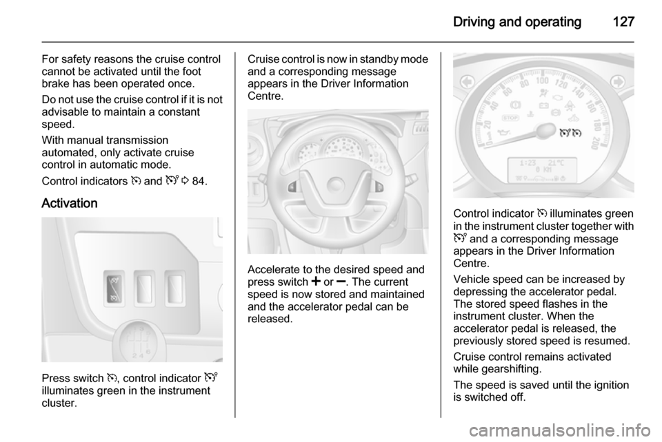
Activation
Press switch m, control indicator U
illuminates green in the instrument
cluster.
Cruise control is now in standby mode
and a corresponding message
appears in the Driver Information
Centre.
Accelerate to the desired speed and
press switch < or ]. The current
speed is now stored and maintained
and the accelerator pedal can be released.
Control indicator m illuminates green
in the instrument cluster together with
U and a corresponding message
appears in the Driver Information
Centre.
Vehicle speed can be increased by
depressing the accelerator pedal. The stored speed flashes in the
instrument cluster. When the
accelerator pedal is released, the previously stored speed is resumed.
Cruise control remains activated
while gearshifting.
The speed is saved until the ignition
is switched off.
Page 130 of 215

128Driving and operating
Increase speedWith cruise control active, the vehicle
speed can be increased continuously or in small increments by holding
down or tapping switch < repeatedly.
When the switch is released the
current speed is stored and
maintained.
Alternatively, accelerate to the
desired speed and store by pressing
switch <.
Reduce speed With cruise control active, the vehicle
speed can be decreased
continuously or in small increments
by holding down or tapping switch ]
repeatedly.
When the switch is released the
current speed is stored and
maintained.
Deactivation
Press switch §: cruise control is
deactivated and the green control
indicator m extinguishes in the
instrument cluster.Automatic deactivation:
■ Vehicle speed drops below 20 mph,
■ The brake pedal is depressed,
■ The clutch pedal is depressed,
■ Selector lever in N.
The speed is stored and a
corresponding message appears in
the Driver Information Centre.
Reactivation
Press switch R at a speed above
20 mph.
If the stored speed is much higher
than the current speed, the vehicle
will accelerate powerfully until the
stored speed is obtained.
Pressing switch < will also reactivate
the cruise control function, but at the
current vehicle speed only, not the
stored speed.
Deleting the stored speed Press switch m: Green control
indicators U and m extinguish in the
instrument cluster.Cruise control speed limiter
The speed limiter prevents the
vehicle exceeding a preset maximum
speed above 20 mph.
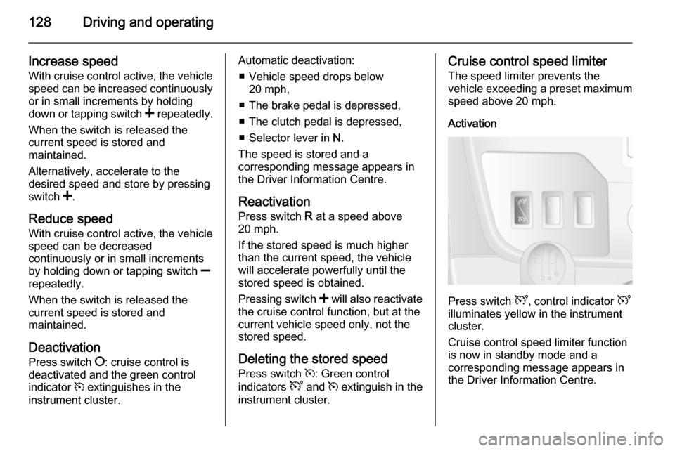
Activation
Press switch U, control indicator U
illuminates yellow in the instrument
cluster.
Cruise control speed limiter function
is now in standby mode and a
corresponding message appears in
the Driver Information Centre.
Page 136 of 215

134Driving and operating
When refuelling is complete, replace
the fuel filler cap and turn it clockwise.
Close the fuel filler flap.
Fuel filler cap
Only use genuine fuel filler caps. Diesel-engined vehicles have special fuel filler caps.
Fuel consumption - CO 2-
Emissions
For the values specific to your
vehicle, refer to the EEC Certificate of Conformity provided with your vehicle
or other national registration
documents.
General information The official fuel consumption and
specific CO 2 emission figures quoted
relate to the EU base model with
standard equipment.
Fuel consumption data and CO 2
emission data are determined
according to regulation
715/2007 692/2008 A, taking intoconsideration the vehicle weight in running order, as specified by the
regulation.
The figures must not be taken as a
guarantee for the actual fuel
consumption of a particular vehicle.
Additional equipment may result in
slightly higher results than the stated
consumption and CO 2 figures.
Furthermore, fuel consumption is dependent on personal driving style
as well as road and traffic conditions.Trailer hitch
General information
Only use towing equipment that has
been approved for your vehicle.
Entrust fitting of towing equipment at
a later date to a workshop. It may be
necessary to make changes that
affect the cooling system, heat
shields or other equipment.
Driving characteristics and
towing tips In the case of trailers with brakes,
attach the breakaway stopping cable.
Before attaching a trailer, lubricate
the coupling ball. However, do not do so if a stabiliser, which acts on thecoupling ball, is being used to reduce
snaking movements. For trailers with
low driving stability the use of a
stabiliser is recommended.
A maximum speed of 50 mph must
not be exceeded, even in countries
where higher speeds are permitted.
Page 137 of 215

Driving and operating135
If the trailer starts snaking, drive moreslowly, do not attempt to correct the
steering and brake sharply if
necessary.
When driving downhill, drive in the
same gear as if driving uphill and
drive at a similar speed.
Adjust tyre pressure to the value
specified for full load 3 201.
Trailer towing Trailer loads
The permissible trailer loads are
vehicle-dependent and engine-
dependent maximum values which
must not be exceeded. The actual
trailer load is the difference between
the actual gross weight of the trailer
and the actual coupling socket load
with the trailer coupled.
The permissible trailer loads are
specified in the vehicle documents. In general, they are valid for gradients
up to max. 12 %.
The permitted trailer load applies up to the specified incline and up to an
altitude of 1000 metres above sealevel. Since engine power decreases as altitude increases due to the airbecoming thinner, therefore reducing
climbing ability, the permissible gross
train weight also decreases by 10 % for every 1000 metres of additional
altitude. The gross train weight does
not have to be reduced when driving on roads with slight inclines (less than 8 %, e.g. motorways).
The permissible gross train weight
must not be exceeded. This weight is
specified on the identification plate
3 182.
Vertical coupling load
The vertical coupling load is the load
exerted by the trailer on the coupling
ball. It can be varied by changing the
weight distribution when loading the
trailer.
The maximum permissible vertical
coupling load is specified on the
towing equipment identification plate
and in the vehicle documents. Always aim for the maximum load, especially
in the case of heavy trailers. The
vertical coupling load should never
fall below 25 kg.In the case of trailer loads of
1200 kg or more, the vertical coupling load should not be less than 50 kg.
Rear axle load When the trailer is coupled and the
towing vehicle fully loaded (including
all occupants), the permissible rear
axle load (see identification plate or
vehicle documents) must not be
exceeded.
Towing equipmentCaution
When operating without a trailer,
remove the coupling ball bar.
Towing equipment audible
warning For vehicles fitted with towing
equipment, when connected to a
trailer the pitch of the audible warning
changes upon operation of the turn
signals.
Page 138 of 215

136Driving and operating
The pitch of the audible warning will
change if a turn signal light on the
trailer or the towing vehicle fails.
Trailer stability assist
If the system detects snaking
movements, engine power is reduced
and the vehicle/trailer combination is
selectively braked until the snaking ceases. While the system is working,keep steering wheel as still as
possible.
Trailer stability assist (TSA) is a
function of the Electronic stability
program (ESP) 3 125.Auxiliary features
Power take-off
Activation
To activate the power take-off, with
the vehicle stationary and the engine
idling:
■ Set the gearshift lever to neutral (vehicles with manual transmissionautomated: selector lever in
position N).
■ Depress the clutch pedal.
■ Press switch on the instrument panel; LED in switch illuminatesafter approx. 2 seconds.
■ Release the clutch pedal.
The engine idle speed increases to
1,200 rpm.Caution
During operation of the power
take-off, never move the selector
lever out of neutral (vehicles with
manual transmission automated:
selector lever in position N), to
avoid damage to the transmission.
If a gear change becomes
necessary, i.e. to adjust the driving
speed, the power take-off must always be deactivated first.
Deactivation
To deactivate the power take-off:
■ Depress the clutch pedal.
■ Press switch on the instrument panel; LED in switch extinguishes
after approx. 2 seconds.
■ Release the clutch pedal.
Page 140 of 215

138Vehicle careVehicle careGeneral Information...................138
Vehicle checks ........................... 139
Bulb replacement .......................147
Electrical system ........................155
Vehicle tools .............................. 158
Wheels and tyres .......................159
Jump starting ............................. 171
Towing ....................................... 174
Appearance care .......................175General Information
Accessories and vehicle
modifications
We recommend the use of genuine parts and accessories and factory
approved parts specific for your
vehicle type. We cannot assess or
guarantee reliability of other products
- even if they have a regulatory or
otherwise granted approval.
Do not make any modifications to the electrical system, e.g. changes of
electronic control units (chip tuning).Caution
When transporting the vehicle on
a train or on a recovery vehicle, the
mud flaps might be damaged.
Vehicle storage
Storage for a long period of time
If the vehicle is to be stored for several months:
■ Wash and wax the vehicle.
■ Have the wax in the engine compartment and underbody
checked.
■ Clean and preserve rubber seals.
■ Change engine oil.
■ Drain washer fluid reservoir.
■ Check coolant antifreeze and corrosion protection.
■ Adjust tyre pressure to the value specified for full load.
■ Park vehicle in a dry, well ventilated
place. Engage first or reverse gear.
Prevent the vehicle from rolling.
■ Do not apply parking brake.
Page 146 of 215

144Vehicle careBrakesIn the event of minimum thickness ofthe brake lining, a squealing noise
sounds during braking.
Continued driving is possible but
have the brake linings replaced as
soon as possible.
Once new brake linings are installed,
do not brake unnecessarily hard for
the first few journeys.
Brake fluid9 Warning
Brake fluid is poisonous and
corrosive. Avoid contact with eyes, skin, fabrics and painted surfaces.
The brake fluid level must be betweenthe MIN and MAX marks.
When topping up, ensure maximum cleanliness as contamination of the
brake fluid can lead to brake system
malfunctions. Have the cause of the
loss of brake fluid remedied by a
workshop.
Only use brake fluid approved for
your vehicle.
Brake and clutch fluid 3 179.
Vehicle battery
The vehicle battery is maintenance-
free provided that the driving profile
allows sufficient charging of the
battery. Short-distance-driving and
frequent engine starts can discharge
the battery. Avoid the use of
unnecessary electrical consumers.
Batteries do not belong in household
waste. They must be disposed of at
an appropriate recycling collection
point.
Laying up the vehicle for more than
4 weeks can lead to battery
discharge. Disconnect the clamp from the negative terminal of the vehicle
battery.
Ensure the ignition is switched off
before connecting or disconnecting
the vehicle battery.
Page 153 of 215

Vehicle care151
5. Detach bulb from bulb holder andrenew the bulb.
6. Insert the bulb holder, engaging the two lugs in the reflectorhousing and rotate clockwise to
secure.
7. Reattach wiring connector to bulb.
8. Replace protective cover.
Tail lights
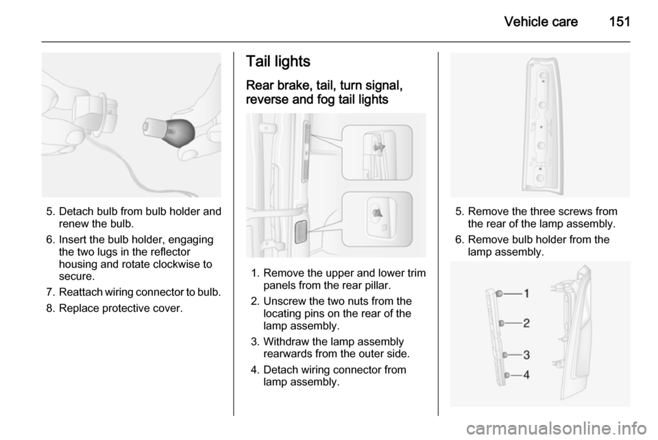
Rear brake, tail, turn signal,
reverse and fog tail lights
1. Remove the upper and lower trim panels from the rear pillar.
2. Unscrew the two nuts from the locating pins on the rear of the
lamp assembly.
3. Withdraw the lamp assembly rearwards from the outer side.
4. Detach wiring connector from lamp assembly.
5. Remove the three screws from the rear of the lamp assembly.
6. Remove bulb holder from the lamp assembly.