Page 131 of 215
![VAUXHALL MOVANO_B 2015.5 Owners Manual Driving and operating129
Accelerate to the desired speed and
press switch < or ]. The current
speed is recorded.
The vehicle can be driven normally
but it will not be possible to exceed the programm VAUXHALL MOVANO_B 2015.5 Owners Manual Driving and operating129
Accelerate to the desired speed and
press switch < or ]. The current
speed is recorded.
The vehicle can be driven normally
but it will not be possible to exceed the programm](/manual-img/38/19555/w960_19555-130.png)
Driving and operating129
Accelerate to the desired speed and
press switch < or ]. The current
speed is recorded.
The vehicle can be driven normally
but it will not be possible to exceed the programmed speed limit except in an
emergency.
Where the limit speed cannot be
maintained, e.g. when driving on a steep decline, the limit speed will
flash in the Driver Information Centre.
Increase limit speed
The limit speed can be increased
continuously or in small increments
by holding down or tapping switch <
repeatedly.
Reduce limit speed
The limit speed can be decreased
continuously or in small increments
by holding down or tapping switch ]
repeatedly.
Exceeding the limit speed
In the event of an emergency it is
possible to exceed the limit speed by
depressing the accelerator pedal
firmly beyond the point of resistance.The limit speed will flash in the Driver Information Centre during this period.
Release the accelerator pedal and
the speed limiter function is
reactivated once a speed lower than the limit speed is obtained.
Notice
In vehicles fitted with a Speed
limiter, fully depressing the
accelerator pedal will not allow you
to exceed the set maximum vehicle
speed. Speed limiter 3 129.
Deactivation
Press switch §: speed limiter is
deactivated and the vehicle can be
driven normally.
The limit speed is stored and a
corresponding message appears in
the Driver Information Centre.
Reactivation
Press switch R. The speed limiter
function is reactivated.
Pressing switch < will also reactivate
the speed limiter function, but at the
current vehicle speed only, not the stored speed.Deleting the limit speed
Press switch U.
Yellow control indicator U
extinguishes in the instrument cluster.
Speed limiter Maximum speed limiterIn accordance with local or national
regulations, the vehicle may be
equipped with a fixed maximum
speed limiter that cannot be disabled.
If equipped, a warning label indicating the fixed maximum speed limit (55 to
80 mph) is located on the instrument
panel.
Deviations from the maximum speed
limit may occur briefly when driving
downhill, for physical reasons.
A warning buzzer will sound for
10 seconds if the vehicle briefly
exceeds the set limit.
Vehicles also equipped with cruise
control speed limiter: the maximum
speed cannot be exceeded by
depressing the accelerator pedal firmly beyond the point of resistance.
Page 133 of 215

Driving and operating131
Deactivation
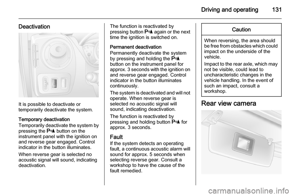
It is possible to deactivate or
temporarily deactivate the system.
Temporary deactivation
Temporarily deactivate the system by
pressing the r button on the
instrument panel with the ignition on
and reverse gear engaged. Control
indicator in the button illuminates.
When reverse gear is selected no
acoustic signal will sound, indicating
deactivation.
The function is reactivated by
pressing button r again or the next
time the ignition is switched on.
Permanent deactivation
Permanently deactivate the system
by pressing and holding the r
button on the instrument panel for
approx. 3 seconds with the ignition on and reverse gear engaged. Control
indicator in the button illuminates
continuously.
The system is deactivated and will not operate. When reverse gear is
selected no acoustic signal will
sound, indicating deactivation.
The function is reactivated by
pressing and holding button r for
approx. 3 seconds.
Fault
If the system detects an operating fault, a continuous acoustic alarm will sound for approx. 5 seconds when
selecting reverse gear. Consult a
workshop to have the cause of the
fault remedied.Caution
When reversing, the area should
be free from obstacles which could impact on the underside of the
vehicle.
Impact to the rear axle, which may
not be visible, could lead to
uncharacteristic changes in the
vehicle handling. In the event of
such an impact, consult a
workshop.
Rear view camera
Page 138 of 215

136Driving and operating
The pitch of the audible warning will
change if a turn signal light on the
trailer or the towing vehicle fails.
Trailer stability assist
If the system detects snaking
movements, engine power is reduced
and the vehicle/trailer combination is
selectively braked until the snaking ceases. While the system is working,keep steering wheel as still as
possible.
Trailer stability assist (TSA) is a
function of the Electronic stability
program (ESP) 3 125.Auxiliary features
Power take-off
Activation
To activate the power take-off, with
the vehicle stationary and the engine
idling:
■ Set the gearshift lever to neutral (vehicles with manual transmissionautomated: selector lever in
position N).
■ Depress the clutch pedal.
■ Press switch on the instrument panel; LED in switch illuminatesafter approx. 2 seconds.
■ Release the clutch pedal.
The engine idle speed increases to
1,200 rpm.Caution
During operation of the power
take-off, never move the selector
lever out of neutral (vehicles with
manual transmission automated:
selector lever in position N), to
avoid damage to the transmission.
If a gear change becomes
necessary, i.e. to adjust the driving
speed, the power take-off must always be deactivated first.
Deactivation
To deactivate the power take-off:
■ Depress the clutch pedal.
■ Press switch on the instrument panel; LED in switch extinguishes
after approx. 2 seconds.
■ Release the clutch pedal.
Page 139 of 215
Driving and operating137
FaultIf the LED in the switch does not
illuminate when attempting to activate the power take-off and/or the system
does not operate:
Gradually release the clutch pedal.
- or - ■ Set the gearshift lever to neutral (vehicles with manual transmission
automated: selector lever in
position N).
■ Depress the clutch pedal.
■ Press switch on the instrument panel; LED in switch illuminatesafter approx. 2 seconds.
■ Release the clutch pedal.
Then repeat the above procedure.
Notice
The power take-off function is not
available when control indicator A
3 80, C 3 80 or W 3 82 is
illuminated.
Page 157 of 215
Vehicle care155Instrument panel
illumination
Have bulbs replaced by a workshop.Electrical system
Fuses Data on the replacement fuse mustmatch the data on the defective fuse.
There are two fuse boxes in the
vehicle:
■ on the left-hand side of the instrument panel, behind the trim
panel.
■ in the engine compartment located below the coolant expansion tank.
Before replacing a fuse, turn off the
respective switch and the ignition.
A blown fuse can be recognised by its melted wire. Do not replace the fuse
until the cause of the fault has been
remedied.
It is advisable to carry a full set of
fuses. Consult a workshop.
Some functions are protected by
several fuses.
Fuses may also be inserted without
existence of a function.
Notice
Not all fuse box descriptions in this
manual may apply to your vehicle.
When inspecting the fuse box, refer to the fuse box label.
Page 158 of 215
156Vehicle care
Fuse extractor
To help in replacing fuses, a fuse
extractor is located in the instrument
panel fuse box.
Place the fuse extractor on the
various types of fuse from the top or
side, and withdraw fuse.
Engine compartment fusebox
Located below the coolant expansion tank.
Some circuits may be protected by
several fuses.
Due to restricted accessibility, have
fuses replaced by a workshop.SymbolCircuitSRight side lightsTLeft side lightsWRight low beamaLeft low beam>Front fog lightLLeft high beamNRight high beamuABSKWindscreen wipernHeating and ventilation
system, air conditioningVHeated windscreen
Page 159 of 215
Vehicle care157Instrument panel fuse box
Located behind the trim panel on the
left-hand side of the instrument panel. Pull upper part of trim panel to
remove.
Do not store any objects behind this
panel.
Some circuits may be protected by
several fuses.
SymbolCircuitZInfotainment system, seat
heating, vehicle display
screen, audio connections,
alarm?Power outletÌCigarette lightereInstrument panelUCentral lockingOTurn signals, rear fog lights,
body control moduleDIAGDiagnostic connectoruABS, Electronic stability
programdInterior lights, brake lightsZBody control moduleSTOPBrake lightIBody control module, power windows, heating and venti‐
lation system, air condi‐
tioningSymbolCircuitmLeft heated rear windownRight heated rear windowRWindscreen washerMElectronic immobiliserUHeated seatsFBLCornering lightlHands-free connection&TachographPTOPower take-offjHornÍPreheating, diesel fuel filterxClimate control fanADPAdditional adaptations,Power windows, body
control module
Page 179 of 215

Vehicle care177
Bitumen/rubber materials could
damage the PVC coating. Have
underbody work carried out by a
workshop.
Before and after winter, wash the
underbody and have the protective
wax coating checked.
Towing equipment
Do not clean the coupling ball bar with
a steam-jet or high-pressure jet
cleaner.
Interior care Interior and upholsteryOnly clean the vehicle interior,
including the instrument panel fascia
and panelling, with a dry cloth or
interior cleaner.
Clean leather upholstery with clear
water and a soft cloth. In case of
heavy soiling, use leather care.
The instrument cluster and the
displays should only be cleaned using
a soft damp cloth. If necessary use a
weak soap solution.Clean fabric upholstery with a
vacuum cleaner and brush. Remove
stains with an upholstery cleaner.
Clothing fabrics may not be
colourfast. This could cause visible discolourations, especially on light-
coloured upholstery. Removable
stains and discolourations should be
cleaned as soon as possible.
Clean seat belts with lukewarm water or interior cleaner.Caution
Close Velcro fasteners as open
Velcro fasteners on clothing could
damage seat upholstery.
The same applies to clothing with
sharp-edged objects, like zips or
belts or studded jeans.
Plastic and rubber parts
Plastic and rubber parts can be
cleaned with the same cleaner as
used to clean the body. Use interior cleaner if necessary. Do not use any
other agent. Avoid solvents and petrol in particular. Do not use high-
pressure jet cleaners.