Page 7 of 276
5
InStruMEntS And controLS
1. Fusebox.
2. Additional programmable heating.
3. Cruise control / sped limiter controls. 4.
Vehicle configuration / Headlamp beam
height / Front/rear foglamps.
5.
Lighting and direction indicator
control stalk.
6. Instrument panel with screen. 7.
Wiper / screenwash / trip computer
control stalk.
8.
Ignition switch.
9. Driver's front airbag / Horn.
10. Steering mounted audio system
controls.
1
OVeRVIeW
Presentation
Page 9 of 276
7
Seat belts 106-108
Airbags 1 10-112
Deactivating the passenger's front airbag 111 , 11 4
Parking brake,
handbrake
98
Front seats, adjustments 71-72
Seat with variable damping 72
2-seat bench 73
Child seats
113-1
16, 119-120
12 volt socket,
uSB port 79, 81-82 Battery (+), charging,
starting
142-144earth point (-) 128, 142
Fuses in the right hand door pillar 145, 147
IntErIor
Seats / rear bench seats 74-75
Rear heating / air
conditioning
65-66
Sliding side door
20
Folding foot board 84
Sliding side windows 83
Rear view mirror
85
Lane departure warning system
105
Cab courtesy lamp 80, 152
Changing a courtesy lamp bulb
149, 152
ISOFIX mountings 117-118
tools, jack 76, 156
Accessories
124
Load space
81-82
● stowing rings,
● load retainer,
● interior roof box,
● side trims,
● 12 volt socket,
● courtesy lamp,
torch 83
IntErIor
1
OVeRVIeW
Location
Page 10 of 276
8
Lane departure warning system 105
Hill descent control 104
Intelligent traction Control 103
ASR, DSC 101-102
Vehicle configuration
90-91
Setting the time 91
Reversing camera 95touch screen audio system 183-230
Audio system 231-247
tachograph 93 Cab fittings
76-80
● cigarette lighter,
● glove box - cooled,
● overhead storage,
● portable ashtray,
● courtesy lamps,
● 12 volt socket / USB port,
● writing table / multifunction
support,
●
storage compartments.
Demisting-defrosting
59
Central locking 22
Locking indicator lamp 22
Hazard warning lamps 98 Ventilation, heating,
A/C
60-62, 63-64
● manual air conditioning,
● mono-zone digital air
conditioning,
●
air recirculation.
Opening the bonnet
127
Dashboard fuses
145-146
InStruMEntS And controLS
Location
Page 12 of 276
10
Changing a wiper blade 155
Bulbs, lighting, changing bulbs
149-154
Very cold conditions protectors 84
Opening the bonnet, stay
127under the bonnet 128
Labels / Precautions 168-171engines 177-178
Identification markings, serial
number
, paint, tyres
182
Levels
129-130
● dipstick,
● brake fluid,
● screenwash / headlamp wash
fluid
●
power steering fluid,
● coolant.
Water bleed, Diesel filter
131
Particle filter 133emission control 33, 139
Checks
131-133
● battery,
● air/passenger compartment filter,● oil filter,
● manual gearbox,
● parking brake,
● brake discs and pads.
tEcHnIcAL dAtA - MAIntEnAncE
Dimensions 172-176
Weights 179-181
engine fuses 145, 148
Location
Page 130 of 276
128
1. Windscreen/headlamp wash fluid
reservoir.
2.
Power steering fluid reservoir.
3.
Coolant header tank.
4.
Brake and clutch fluid reservoir.
5.
Fusebox.
6.
Air filter.
7.
Dipstick.
8.
e
ngine oil filler cap.
undErBonnEt - dIESEL
EnGInES
Battery connections:
+
Positive terminal.
-
Negative terminal (earth).
to understand the significance of the
precautions mentioned on the labels,
refer to the "Quick help -
glossary of
labels" section.
under the bonnet
Page 147 of 276

145
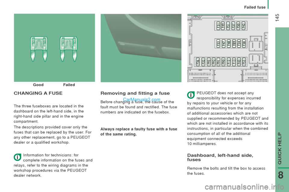
the three fuseboxes are located in the
dashboard on the left-hand side, in the
right-hand side pillar and in the engine
compartment.
the descriptions provided cover only the
fuses that can be replaced by the user. For
any other replacement, go to a P
eugeOt
dealer or a qualified workshop.
removing and fitting a fuse
Before changing a fuse, the cause of the
fault must be found and rectified.
the fuse
numbers are indicated on the fusebox.
Always replace a faulty fuse with a fuse
of the same rating.
cHAnGInG A FuSEPeugeOt does not accept any
responsibility for expenses incurred
by repairs to your vehicle or for any
malfunctions resulting from the installation
of additional accessories which are not
supplied or recommended by P
eugeOt and
which are not installed in accordance with its
instructions, in particular when the combined
consumption of all of the additional
equipment connected exceeds
10 milliamperes.
Good
Failed
Information for technicians: for
complete information on the fuses and
relays, refer to the wiring diagrams in the
workshop procedures via the P
eugeOt
dealer network.
dashboard, left-hand side,
fuses
Remove the bolts and tilt the box to access
the fuses.
QuICK HeLP
8
Failed fuse
Page 150 of 276
148
Fuses in the engine compartment
Remove the nuts and tilt the box to access
the fuses.
refit the cover carefully after checking or
replacing fuses. Fuses
A (amps) Allocation
1 40ABS pump supply
2 50Diesel pre-heat unit
3 30Ignition switch - Starter motor
4 40Fuel heater
5 20/50Cabin ventilation with additional programmable heating
(battery +)
6 40/60Cabin fan maximum speed (battery +)
7 40/50/60 Cabin fan minimum speed (battery +)
8 40Cabin fan assembly (ignition switch +)
9 15Rear 12 V socket (battery +)
10 15Horn
11 -Not used
14 15Front 12 V socket (battery +)
15 15Cigarette lighter (battery +)
16 -Not used
17 -Not used
18 7.5
engine management control unit (battery +)
19 7.5Air conditioning compressor
20 30Screenwash/headlamp wash pump
21 15Fuel pump supply
22 -Not used
23 30ABS electrovalves
24 7.5Auxiliary switch panel - Door mirror controls and folding
(ignition switch +)
30 15Door mirror heating
Failed fuse