2014 YAMAHA YZ250F Valves
[x] Cancel search: ValvesPage 36 of 356

STARTING AND BREAK-IN
1-22
EAS1SM1041
STARTING AND BREAK-IN
EAS1SM1042FUEL
Always use the recommended fuel as stated
below. Also, be sure to use new gasoline the
day of a race.
JCA
NOTICE
Use only unleaded gasoline. The use of
leaded gasoline will cause severe damage
to the engine internal parts such as valves,
piston rings, and exhaust system, etc.
TIP
Your Yamaha engine has been designed to use
premium unleaded gasoline with a pump oc-
tane number [(R+M)/2] of 91 or higher, or a re-
search octane number of 95 or higher. If
knocking (or pinging) occurs, use a gasoline of
a different brand.
JWA
WARNING
• For refueling, be sure to stop the engine and use enough care not to spill any fuel.
Also be sure to avoid refueling close to a
fire.
• Refuel after the engine, exhaust pipe, etc.
have cooled off.
Gasohol (For USA and Canada)
There are two types of gasohol: gasohol con-
taining ethanol and that containing methanol.
Gasohol containing ethanol can be used if the
ethanol content does not exceed 10%. Gasohol
containing methanol is not recommended by
Yamaha because it can cause damage to the
fuel system or vehicle performance problems.
EAS1SM1043STARTING A COLD ENGINE
1. Press the shift pedal to neutral.
2. Pull the starter knob/idle screw “1” to its full length.
TIP
When the ambient temperature is 15°C (59°F)
or below, use the starter knob/idle screw. 3. Push down the kickstarter lever lightly until
resistance is felt.
4. Fully close the throttle, and push down the kickstarter lever in a stroke.
5. Immediately release the kickstarter lever.
EWA
WARNING
Do not open the throttle at the moment
when you kick the kickstarter lever, be-
cause this may kick back
TIP
If it fails to start, fully open the throttle grip and
give 10 to 20 slow kicks to clear the engine of
the rich air-fuel mixture retained in it.
6. When the engine starts running, warm this
up one or two minutes at a steady speed (of
3000 to 5000 r/min), and then return the
starter knob/idle screw to its original posi-
tion.
EWA
WARNING
Since exhaust gas contains harmful ingre-
dients, do not start or warm it up at an ill-
ventilated place or a closed narrow place.
Recommended fuel
Premium unleaded gasoline
Fuel tank capacity 7.5 L (1.98 US gal, 1.65 lmp.gal)
1
Page 191 of 356

5
ENGINE
ENGINE REMOVAL......................................................................................... 5-1
REMOVING THE SILENCER ..................................................................... 5-6
REMOVING THE EXHAUST PIPE 2.......................................................... 5-6
REMOVING THE DRIVE SPROCKET ....................................................... 5-6
REMOVING THE ENGINE ......................................................................... 5-7
CHECKING THE SILENCER AND EXHAUST PIPE.................................. 5-7
CHANGING THE SILENCER FIBER ......................................................... 5-7
INSTALLING THE ENGINE........................................................................ 5-8
INSTALLING THE BRAKE PEDAL ............................................................ 5-9
INSTALLING THE DRIVE SPROCKET...................................................... 5-9
INSTALLING THE EXHAUST PIPE AND MUFFLER............................... 5-10
CAMSHAFT.................................................................................................... 5-11
REMOVING THE CAMSHAFT ................................................................. 5-13
CHECKING THE CAMSHAFT.................................................................. 5-14
CHECKING THE TIMING CHAIN AND CAMSHAFT SPROCKET .......... 5-15
CHECKING THE TIMING CHAIN TENSIONERS .................................... 5-15
CHECKING THE DECOMPRESSION SYSTEM...................................... 5-16
INSTALLING THE CAMSHAFTS ............................................................. 5-16
CYLINDER HEAD........................................................................................... 5-18
REMOVING THE CYLINDER HEAD........................................................ 5-20
CHECKING THE TIMING CHAIN GUIDE (INTAKE SIDE) ...................... 5-20
CHECKING THE CYLINDER HEAD ........................................................ 5-20
INSTALLING THE CYLINDER HEAD ...................................................... 5-21
VALVES AND VALVE SPRINGS................................................................... 5-22
REMOVING THE VALVES ....................................................................... 5-23
CHECKING THE VALVES AND VALVE GUIDES ................................... 5-24
CHECKING THE VALVE SEATS ............................................................. 5-25
CHECKING THE VALVE SPRINGS......................................................... 5-27
CHECKING THE VALVE LIFTERS .......................................................... 5-27
INSTALLING THE VALVES ..................................................................... 5-28
CYLINDER AND PISTON............................................................................... 5-30
REMOVING THE PISTON ....................................................................... 5-31
CHECKING THE CYLINDER AND PISTON ............................................ 5-31
CHECKING THE PISTON RINGS............................................................ 5-32
CHECKING THE PISTON PIN ................................................................. 5-33
INSTALLING THE PISTON AND CYLINDER .......................................... 5-33
Page 215 of 356

VALVES AND VALVE SPRINGS
5-22
EAS1SM1219
VALVES AND VALVE SPRINGS
Removing the valves and valve springs
Order Part name Q’ty Remarks
Cylinder headRefer to “CYLINDER HEAD” on page 5-18.
1Valve lifter
4
2Adjusting pad
4
3Valve cotter
8
4Valve spring retainer
4
5Valve spring
4
6Valve stem seal
4
7Valve spring seat
4
8Intake valve
2
9Exhaust valve
2
For installation, reverse the removal proce-
dure.
Page 216 of 356
VALVES AND VALVE SPRINGS
5-23
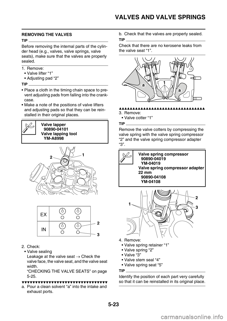
EAS1SM1220REMOVING THE VALVES
TIP
Before removing the internal parts of the cylin-
der head (e.g., valves, valve springs, valve
seats), make sure that the valves are properly
sealed.
1. Remove:
• Valve lifter “1”
• Adjusting pad “2”
TIP
• Place a cloth in the timing chain space to pre-
vent adjusting pads from falling into the crank-
case.
• Make a note of the positions of valve lifters
and adjusting pads so that they can be rein-
stalled in their original places.
2. Check:
• Valve sealing
Leakage at the valve seat Check the
valve face, the valve seat, and the valve seat
width.
“CHECKING THE VALVE SEATS” on page
5-25.
▼▼▼▼▼▼▼▼▼▼▼▼▼▼▼▼▼▼▼▼▼▼▼▼▼▼▼▼▼▼▼▼
a. Pour a clean solvent “a” into the intake and
exhaust ports.b. Check that the valves are properly sealed.
TIP
Check that there are no kerosene leaks from
the valve seat “1”.
▲▲▲▲▲▲▲▲▲▲▲▲▲▲▲▲▲▲▲▲▲▲▲▲▲▲▲▲▲▲▲▲
3. Remove:
• Valve cotter “1”
TIP
Remove the valve cotters by compressing the
valve spring with the valve spring compressor
“2” and the valve spring compressor adapter
“3”.
4. Remove:
• Valve spring retainer “1”
• Valve spring “2”
•Valve “3”
• Valve stem seal “4”
• Valve spring seat “5”
TIP
Identify the position of each part very carefully
so that it can be reinstalled in its original place. Valve lapper
90890-04101
Valve lapping tool
YM-A8998
1
2Valve spring compressor
90890-04019
YM-04019
Valve spring compressor adapter
22 mm
90890-04108
YM-04108
a1
a
Page 217 of 356

VALVES AND VALVE SPRINGS
5-24
EAS1SM1221CHECKING THE VALVES AND VALVE
GUIDES
1. Measure:
• Valve-stem-to-valve-guide clearance
Out of specification Replace the valve
guide.2. Replace:
• Valve guide
TIP
To ease valve guide removal and installation,
and to maintain the correct fit, heat the cylinder
head to 100 °C (212 °F) in an oven.
▼▼▼▼▼▼▼▼▼▼▼▼▼▼▼▼▼▼▼▼▼▼▼▼▼▼▼▼▼▼▼▼
a. Remove the valve guide with the valve guide
remover “1”.
b. Install the new valve guide with the valve
guide installer “2” and the valve guide re-
mover “1”.
c. After installing the valve guide, expand the
hole in the valve guide with the valve guide
reamer “3” to obtain the proper valve-stem-
to-valve-guide clearance. Valve-stem-to-valve-guide clearance =
Valve guide inside diameter “a” -
Valve stem diameter “b”
Valve-stem-to-valve-guide clear-
ance (intake)
0.010–0.037 mm (0.0004–0.0015
in)
Limit
0.080 mm (0.0032 in)
Valve-stem-to-valve-guide clear-
ance (exhaust)
0.025–0.052 mm (0.0010–0.0020
in)
Limit
0.100 mm (0.0039 in)
1
2
4
5
3
Valve guide installation height “a”
Intake
10.8–11.2 mm (0.43–0.44 in)
Exhaust
11.2–11.6 mm (0.44–0.46 in)
1
Page 218 of 356

VALVES AND VALVE SPRINGS
5-25
TIP
After replacing the valve guide, reface the valve
seat.
▲▲▲▲▲▲▲▲▲▲▲▲▲▲▲▲▲▲▲▲▲▲▲▲▲▲▲▲▲▲▲▲
3. Eliminate:• Carbon deposits(from the valve face and valve seat)
4. Check: • Valve facePitting/wear Grind the valve face.
• Valve stem end Mushroom shape or diameter larger than
the body of the valve stem Replace the
valve.
5. Measure: • Valve margin thickness D “a”Out of specification Replace the valve. 6. Measure:
• Valve stem runoutOut of specification Replace the valve.
TIP
• When installing a new valve, always replace
the valve guide.
• If the valve is removed or replaced, always re-
place the oil seal.
EAS1SM1222CHECKING THE VALVE SEATS
1. Eliminate: • Carbon deposits(from the valve face and valve seat)
2. Check:
• Valve seatPitting/wear Replace the cylinder head.
3. Measure:
• Valve seat width C “a”Out of specification Replace the cylinder
head.
▼▼▼▼▼▼▼▼▼▼▼▼▼▼▼▼▼▼▼▼▼▼▼▼▼▼▼▼▼▼▼▼
a. Apply Mechanic’s blueing dye (Dykem) “b” onto the valve face.
Intake
Valve guide remover (ø5.0)
90890-04097
YM-04097
Valve guide installer (ø5.0) 90890-04098
YM-04098
Valve guide reamer (ø5.0) 90890-04099
YM-04099
Exhaust
Valve guide remover (ø4.5)
90890-04116
YM-04116
Valve guide installer (ø4.5)
90890-04117
YM-04117
Valve guide reamer (ø4.5)
90890-04118
YM-04118
Valve margin thickness D (intake) 1.20 mm (0.0472 in)
Valve margin thickness D (ex-
haust) 0.85 mm (0.0335 in)
Valve stem runout 0.010 mm (0.0004 in)
Valve seat width C (intake) 0.90–1.10 mm (0.0354–0.0433 in)
Valve seat width C (exhaust) 0.90–1.10 mm (0.0354–0.0433 in)
Page 219 of 356

VALVES AND VALVE SPRINGS
5-26
b. Install the valve into the cylinder head.
c. Press the valve through the valve guide and
onto the valve seat to make a clear impres-
sion.
d. Measure the valve seat width “c”.
TIP
Where the valve seat and the valve face are in
contact with each other, the blueing will have
been removed.
▲▲▲▲▲▲▲▲▲▲▲▲▲▲▲▲▲▲▲▲▲▲▲▲▲▲▲▲▲▲▲▲
4. Lap:
• Valve face
• Valve seat
ECA1DX1018
NOTICE
This model uses titanium intake and ex-
haust valves.
Do not use the valves used for lapping the
valve seat. Always replace the valves used
for lapping with new ones.
TIP
• When replacing the cylinder head, replace
also the valves with new ones without them.
• When replacing the valves or the valve
guides, use new valves to lap the valve seats,
and then replace them with new valves.
▼▼▼▼▼▼▼▼▼▼▼▼▼▼▼▼▼▼▼▼▼▼▼▼▼▼▼▼▼▼▼▼
a. Apply a coarse lapping compound “a” to the
valve face.
ECA13790
NOTICE
Do not let the lapping compound enter the
gap between the valve stem and the valve
guide.
b. Apply molybdenum disulfide oil onto the
valve stem.
c. Install the valve into the cylinder head.
d. Turn the valve until the valve face and the
valve seat are evenly polished, then clean
off all of the lapping compound.
TIP
While turning the valve lapper, tap and lap the
valve seat.
e. Apply a fine lapping compound to the valve
face, and repeat the above steps.
f. After every lapping step, be sure to clean off
all of the lapping compound from the valve
face and the valve seat.
g. Apply Mechanic’s blueing dye (Dykem) “b”
onto the valve face.
h. Install the valve into the cylinder head.
i. Press the valve through the valve guide and
onto the valve seat to make a clear impres-
sion.
j. Measure the valve seat width “c” again. If the
valve seat width is out of specification,
reface and lap the valve seat.
c
Page 220 of 356

VALVES AND VALVE SPRINGS
5-27
▲▲▲▲▲▲▲▲▲▲▲▲▲▲▲▲▲▲▲▲▲▲▲▲▲▲▲▲▲▲▲▲EAS1SM1223CHECKING THE VALVE SPRINGS
1. Measure:
• Valve spring free length “a”
Out of specification Replace the valve
spring.
2. Measure:
• Compressed valve spring force “a”
Out of specification Replace the valve
spring.3. Measure:
• Valve spring tilt “a”
Out of specification Replace the valve
spring.
EAS1SM1224CHECKING THE VALVE LIFTERS
1. Check:
• Valve lifter
Damage/scratches Replace the valve lift-
ers and cylinder head.
EAS1SM1225
Free length (intake)
36.69 mm (1.44 in)
Limit
35.69 mm (1.41 in)
Free length (exhaust)
34.86 mm (1.37 in)
Limit
33.86 mm (1.33 in)
b. Installed length
Installed compression spring
force (intake)
146.00–168.00 N (14.89–17.13
kgf, 32.82–37.77 lbf)
Installed compression spring
force (exhaust)
137.00–157.00 N (13.97–16.01
kgf, 30.80–35.29 lbf)
Installed length (intake)
31.40 mm (1.24 in)
Installed length (exhaust)
28.50 mm (1.12 in)
Spring tilt (intake)
2.5 °/1.6 mm (2.5 °/0.06 in)
Spring tilt (exhaust)
2.5 °/1.5 mm (2.5 °/0.06 in)