Page 8 of 180

Rough terrain................................. 7-24
Pavement ...................................... 7-24
Water ............................................. 7-24
Loose terrain/slippery terrain......... 7-25
Brush or wooded areas ................. 7-26
Encountering obstacles ................. 7-26
PERIODIC MAINTENANCE AND
ADJUSTMENT .................................. 8-1 Owner’s manual and tool kit ............ 8-2
Periodic maintenance chart for the emission control system ................ 8-4
General maintenance and lubrication chart ............................. 8-5
Hood ................................................ 8-7
Engine oil and oil filter cartridge ...... 8-9
Final gear oil .................................. 8-15
Differential gear oil......................... 8-17
Coolant .......................................... 8-20
Axle boots ...................................... 8-21
Spark plug inspection .................... 8-22
Cleaning the air filter element ....... 8-25 Cleaning the air filter case/duct
check hose ...................................8-29
V-belt case drain plug ....................8-30
Cleaning the spark arrester ...........8-30
Valve clearance .............................8-31
Brakes ............................................8-32
Checking the front and rear brake pads .............................................8-32
Checking the parking brake pads .............................................8-33
Checking the brake fluid level........8-33
Brake fluid replacement .................8-34
Checking the brake pedal ..............8-35
Parking brake lever free play
adjustment ...................................8-35
Brake light switch adjustment ........8-36
Cable inspection and lubrication....8-37
Brake pedal and accelerator pedal lubrication.....................................8-37
Checking the stabilizer bushes ......8-38
Rear knuckle upper and lower
pivot lubrication (left and right).....8-38
Steering shaft lubrication ...............8-39
81XP7B_EE.book Page 3 Tuesday, February 4, 2014 3:40 PM
Page 31 of 180
3-1
1
23
4
5
6
7
8
9
10
11
12
13
14
EVU00080
1-DESCRIPTION
1. Headlight
2. Front shock absorber assembly
3. Brake fluid reservoir
4. Driver seat
5. Driver seat belt
6. Shoulder bolster
7. Cargo bed
8. Tail/brake light
9. Spark arrester
10. Rear shock absorber assembly
11. Spark plug
12. Cargo bed release lever
13. Storage compartment
14. Door 15. Engine oil dipstick
16. Passenger seat belt
17. Passenger seat
18. Air filter
19. Battery
20. Fuses
21. Radiator cap
22. Coolant reservoir
23. Storage compartment
24. Fuel tank cap
25. Oil filter cartridge123
8
7
90AB
D
C 65
4
ON
ML IJ K
HGFE
1XP7B_EE.book Page 1 Tuesday, February 4, 2014 3:40 PM
Page 115 of 180

8-5
1
2
3
4
5
6
78
9
10
11
12
13
14
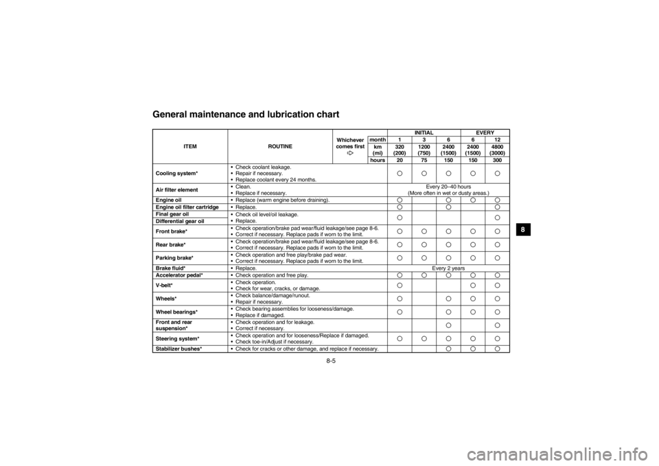
EVU01650General maintenance and lubrication chart
ITEM ROUTINEWhichever
comes first INITIAL
EVERY
month136612 km
(mi) 320
(200) 1200
(750) 2400
(1500) 2400
(1500) 4800
(3000)
hours 20 75 150 150 300
Cooling system* Check coolant leakage.
Repair if necessary.
Replace coolant every 24 months.
Air filter element
Clean.
Replace if necessary. Every 20–40 hours
(More often in wet or dusty areas.)
Engine oil Replace (warm engine before draining).Engine oil filter cartridge Replace.Final gear oil
Check oil level/oil leakage.
Replace.Differential gear oil
Front brake* Check operation/brake pad wear/fluid leakage/see page 8-6.
Correct if necessary. Replace pads if worn to the limit.Rear brake* Check operation/brake pad wear/fluid leakage/see page 8-6.
Correct if necessary. Replace pads if worn to the limit.Parking brake*
Check operation and free play/brake pad wear.
Correct if necessary. Replace pads if worn to the limit.Brake fluid*
Replace. Every 2 years
Accelerator pedal* Check operation and free play.V-belt* Check operation.
Check for wear, cracks, or damage.Wheels* Check balance/damage/runout.
Repair if necessary.Wheel bearings*
Check bearing assemblies for looseness/damage.
Replace if damaged.Front and rear
suspension* Check operation and for leakage.
Correct if necessary.Steering system*
Check operation and for looseness/Replace if damaged.
Check toe-in/Adjust if necessary.Stabilizer bushes*
Check for cracks or other damage, and replace if necessary.
1XP7B_EE.book Page 5 Tuesday, February 4, 2014 4:19 PM
Page 119 of 180
8-9
1
2
3
4
5
6
78
9
10
11
12
13
14
5B410012Engine oil and oil filter cartridgeCheck engine oil level before each operation.
In addition, change the oil and the oil filter car-
tridge at the intervals specified in the periodic
maintenance and lubrication chart.
To check the engine oil level1. Park the vehicle on a level surface.
2. Lift the cargo bed up. (See page 4-26 for cargo bed lifting and lowering proce-
dures.)
3. Check the engine oil level on a cold en-
gine. TIPIf the engine was started before checking the
oil level, be sure to warm up the engine suffi-
ciently, and then wait at least 10 minutes until
the oil settles for an accurate reading.4. Remove the engine oil dipstick, and thenwipe it off with a clean rag.
1. Engine oil dipstick
1
1XP7B_EE.book Page 9 Tuesday, February 4, 2014 3:40 PM
Page 121 of 180
8-11
1
2
3
4
5
6
78
9
10
11
12
13
14
To change the engine oil (with or without
oil filter cartridge replacement)1. Park the vehicle on a level surface.
2. Lift the cargo bed up. (See page 4-26 for
cargo bed lifting and lowering proce-
dures.)
3. Start the engine, warm it up for several minutes, and then turn it off.
4. Place an oil pan under the engine to col-
lect the used oil, and then remove the
dipstick.
5. Remove the engine oil drain bolt and its
gasket to drain the oil from the crank-
case.
1. Engine oil drain bolt 2. GasketTIPSkip steps 6–8 if the oil filter cartridge is not
being replaced.
1 2
1XP7B_EE.book Page 11 Tuesday, February 4, 2014 3:40 PM
Page 122 of 180
8-12
8
9
10
11
12
13
14
6. Remove the oil filter cartridge with an oil filter wrench. Make sure that the O-ring is
removed together with the oil filter car-
tridge. If the O-ring remains attached to
the crankcase, oil leakage may occur.TIPAn oil filter wrench is available from a Yamaha
dealer. 1. Oil filter cartridge 2. Oil filter wrench7. Apply a light coat of clean engine oil tothe O-ring of the new oil filter cartridge.
TIPMake sure that the O-ring is properly seated.1. O-ring8. Install the new oil filter cartridge with an oil filter wrench, and then tighten it to the
specified torque with a torque wrench.
2
1
Tightening torque:Oil filter cartridge: 17 Nm (1.7 m·kgf, 12 ft·lbf)
1XP7B_EE.book Page 12 Tuesday, February 4, 2014 3:40 PM
Page 123 of 180
8-13
1
2
3
4
5
6
78
9
10
11
12
13
14
1. Torque wrench9. Install the engine oil drain bolt and itsnew gasket, and then tighten the bolt to
the specified torque.
10. Remove the right rear panel by removing the quick fastener screws and bolts.
1. Right rear panel 2. Quick fastener screw (× 4)
3. Bolt ( × 2)11. Refill with the specified amount of recom-
mended engine oil, and then insert the
dipstick completely into the oil filler hole.
Tightening torque: Engine oil drain bolt:
30 Nm (3.0 m·kgf, 22 ft·lbf)
1
Recommended engine oil:See page 10-1.
Oil quantity:
Without oil filter cartridge replacement: 2.20 L (2.33 US qt, 1.94 Imp.qt)
With oil filter cartridge replacement:
2.30 L (2.43 US qt, 2.02 Imp.qt)
1
2
3
1XP7B_EE.book Page 13 Tuesday, February 4, 2014 3:40 PM
Page 138 of 180

8-28
8
9
10
11
12
13
14
8. Wash the sponge material in warm soapy water to remove remaining solvent, then
rinse thoroughly with plain warm water.
9. Squeeze excess water out of the sponge material. NOTICE: Do not twist the
sponge material when squeezing it.
10. Allow the sponge material to dry thor- oughly. Inspect the sponge material and
replace it if damaged.
11. Thoroughly apply Yamaha foam air filter oil or other quality liquid foam air filter oil
(not spray type) to the sponge material.
The sponge material should be wet but
not dripping.
12. Pull the sponge material over its frame.
13. Install the air filter element holder.
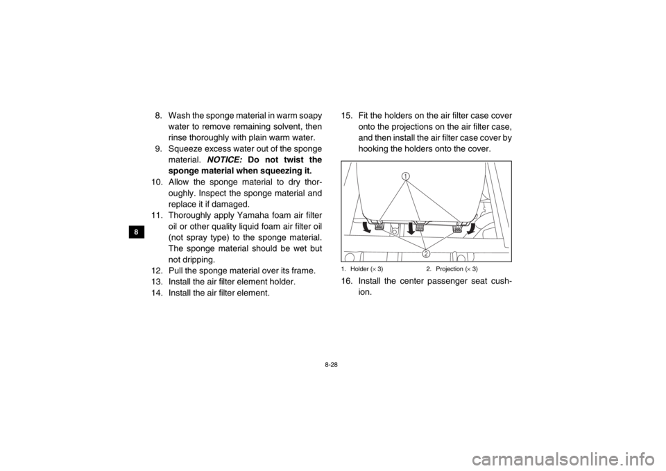
14. Install the air filter element. 15. Fit the holders on the air filter case cover
onto the projections on the air filter case,
and then install the air filter case cover by
hooking the holders onto the cover.
1. Holder ( × 3) 2. Projection ( × 3)16. Install the center passenger seat cush-
ion.
1
2
1XP7B_EE.book Page 28 Tuesday, February 4, 2014 3:40 PM