2014 VOLVO S80 tire pressure
[x] Cancel search: tire pressurePage 281 of 380

07 During your trip
Towing a trailer
07
279
Introduction
Volvo recommends the use of Volvo trailer hitches that are specially designed for thevehicle.
NOTE
See page 359 for the maximum trailer and tongue weights recommended by Volvo.
•Observe the legal requirements of the state/province in which the vehicles are
• All Volvo models are equipped withenergy-absorbing shock-mounted bump-ers. Trailer hitch installation should notinterfere with the proper operation of thisbumper system.
Trailer towing does not normally present any particular problems, but take into considera-tion: • Increase tire pressure to recommended full pressure. See the tire inflation tableon page 293.
• When your vehicle is new, avoid towingheavy trailers during the first 620 miles(1,000 km).
• Maximum speed when towing a trailer:50 mph (80 km/h).
• Engine and transmission are subject toincreased loads. Therefore, engine cool-ant temperature should be closely watched when driving in hot climates orhilly terrain. Use a lower gear and turn offthe air conditioner if the temperaturegauge needle enters the red range.
• If the automatic transmission begins tooverheat, a message will be displayed inthe text window.
• Avoid overload and other abusive opera-tion.
• Hauling a trailer affects handling, durabil-ity, and economy.
• It is necessary to balance trailer brakeswith the towing vehicle brakes to providea safe stop (check and observe state/local regulations).
• Do not connect the trailer's brake systemdirectly to the vehicle's brake system.
• More frequent vehicle maintenance isrequired.
• Remove the ball holder when the hitch isnot being used.
WARNING
• Bumper-attached trailer hitches must not be used on Volvos, nor shouldsafety chains be attached to thebumper.
• Trailer hitches attaching to the vehiclerear axle must not be used.
• Never connect a trailer's hydraulicbrake system directly to the vehiclebrake system, nor a trailer's lightingsystem directly to the vehicle lightingsystem. Consult your nearest author-ized Volvo retailer for correct installa-tion.
• When towing a trailer, the trailer'ssafety wire must be correctly fastenedto the hole or hook provided in thetrailer hitch on the vehicle. The safetywire should never be fastened to orwound around the drawbar ball.
Page 284 of 380
07 During your trip
Emergency towing
07
282
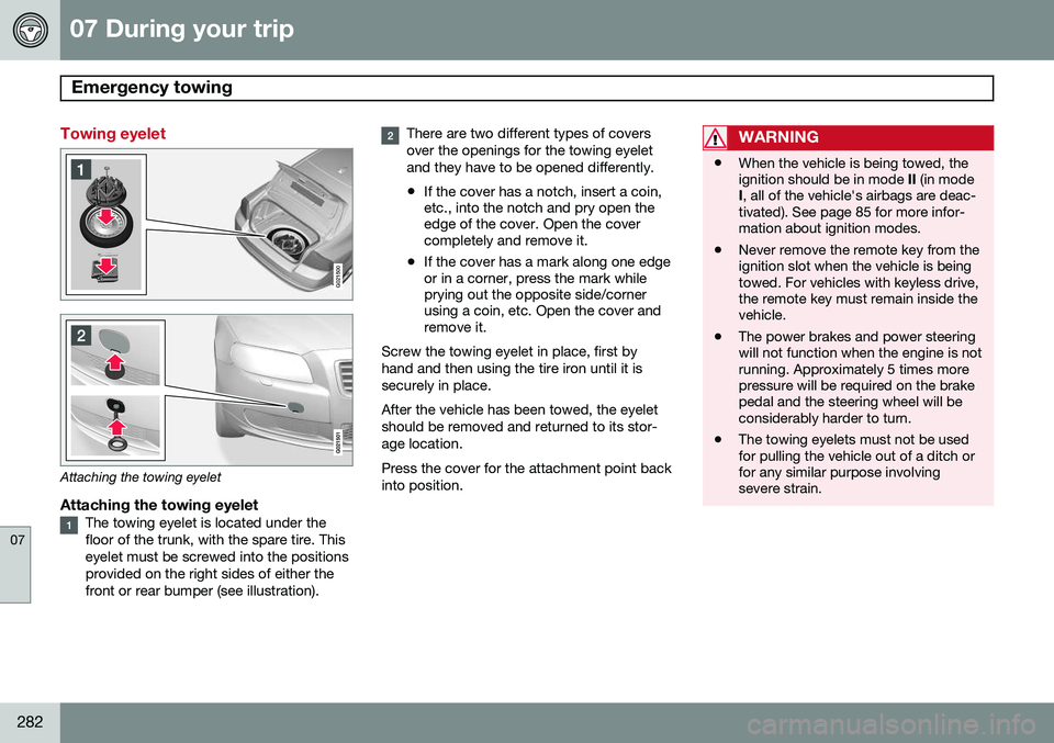
Towing eyelet
G021500
Attaching the towing eyelet
Attaching the towing eyeletThe towing eyelet is located under the floor of the trunk, with the spare tire. Thiseyelet must be screwed into the positionsprovided on the right sides of either thefront or rear bumper (see illustration).
There are two different types of covers over the openings for the towing eyeletand they have to be opened differently.
• If the cover has a notch, insert a coin, etc., into the notch and pry open theedge of the cover. Open the covercompletely and remove it.
• If the cover has a mark along one edgeor in a corner, press the mark whileprying out the opposite side/cornerusing a coin, etc. Open the cover andremove it.
Screw the towing eyelet in place, first by hand and then using the tire iron until it issecurely in place. After the vehicle has been towed, the eyelet should be removed and returned to its stor-age location. Press the cover for the attachment point back into position.WARNING
• When the vehicle is being towed, the ignition should be in mode
II (in mode
I , all of the vehicle's airbags are deac-
tivated). See page 85 for more infor-mation about ignition modes.
• Never remove the remote key from theignition slot when the vehicle is beingtowed. For vehicles with keyless drive,the remote key must remain inside thevehicle.
• The power brakes and power steeringwill not function when the engine is notrunning. Approximately 5 times morepressure will be required on the brakepedal and the steering wheel will beconsiderably harder to turn.
• The towing eyelets must not be usedfor pulling the vehicle out of a ditch orfor any similar purpose involvingsevere strain.
Page 285 of 380

07 During your trip
Emergency towing
07
283
Towing the vehicle
1. With the remote key fully pressed into theignition slot 1
, press START/STOP
ENGINE for approximately 2 seconds to
activate ignition mode II.
2. The remote key must remain in the igni- tion slot 2
for the entire time that the vehi-
cle is being towed.
3. Keep the tow rope taut when the towing vehicle slows down by applying light pressure on the brake pedal. This willhelp prevent jarring movements of thevehicle being towed.
4. Be prepared to apply the brakes to stop the vehicle being towed.CAUTION
General towing precautions:
• Please check with state and local authorities before attempting this typeof towing, as vehicles being towed aresubject to regulations regarding maxi-mum towing speed, length and type oftowing device, lighting, etc.
• If the vehicle's battery is dead, attachjumper cables (see page 119) to pro-vide current for releasing the electricparking brake and to move the gearselector from the
P position to N. If
this is not possible, see page 124 forinformation about manually overridingthe shiftlock system to move the gearselector from P to N.
• Maximum speed: 50 mph (80 km/h).Do not exceed the maximum allowabletowing speed.
• Maximum distance with front wheelson ground: 50 miles (80 km).
• The vehicle should only be towed inthe forward direction.
Having the vehicle towed by a tow truck
Call for professional help from an authorized towing company.Volvo recommends the useof flat bed equipment. The towing eyelet may be used to pull the vehicle onto a flatbed tow truck if:
• The angle of the tow truck’s ramp is not more than 12 degrees from a horizontalplane
• The vehicle’s wheels rotate freely and rollstraight ahead
WARNING
No person or object should be behind the tow truck while the vehicle is being pulledup onto the flatbed.
1
Not necessary in vehicles with the optional keyless drive.
2 For vehicles with the the optional keyless dirive, the remote key must be in the vehicle.
Page 288 of 380

286* Option/accessory, for more information, see Introduction. General information .............................................................................. 288 Tire inflation........................................................................................... 291
Inflation pressure .................................................................................293
Tire designations ..................................................................................294
Glossary of tire terminology ................................................................. 296Vehicle loading ..................................................................................... 297
Uniform Tire Quality Grading ............................................................... 299
Snow chains, snow tires, studded tires ............................................... 300
Temporary Spare ................................................................................. 301
Tire Sealing System*............................................................................. 302
Changing a wheel ................................................................................ 308
Tire Pressure Monitoring System (TPMS)............................................. 311
Page 291 of 380
08 Wheels and tires
General information
08
}}
289
process. The temporary spare
1
should also
be replaced at 6-year intervals, even if it has never been used. A tire's age can be determined by the DOT stamp on the sidewall (see the illustration). A tire with e.g., visible cracks or discoloration should be replaced immediately.
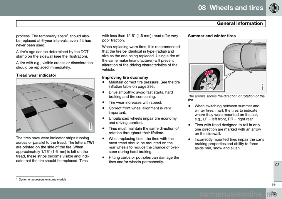
Tread wear indicator
G021829
The tires have wear indicator strips running across or parallel to the tread. The letters TWI
are printed on the side of the tire. Whenapproximately 1/16" (1.6 mm) is left on thetread, these strips become visible and indi-cate that the tire should be replaced. Tires with less than 1/16" (1.6 mm) tread offer verypoor traction. When replacing worn tires, it is recommended that the tire be identical in type (radial) andsize as the one being replaced. Using a tire ofthe same make (manufacturer) will preventalteration of the driving characteristics of thevehicle.
Improving tire economy
•
Maintain correct tire pressure. See the tire inflation table on page 293.
• Drive smoothly: avoid fast starts, hardbraking and tire screeching.
• Tire wear increases with speed.
• Correct front wheel alignment is veryimportant.
• Unbalanced wheels impair tire economyand driving comfort.
• Tires must maintain the same direction ofrotation throughout their lifetime.
• When replacing tires, the tires with themost tread should be mounted on therear wheels to reduce the chance of over-steer during hard braking.
• Hitting curbs or potholes can damage thetires and/or wheels permanently.
Summer and winter tires
G021778
The arrows shows the direction of rotation of the tire
• When switching between summer and winter tires, mark the tires to indicatewhere they were mounted on the car,e.g., LF = left front, RR = right rear
• Tires with tread designed to roll in onlyone direction are marked with an arrowon the sidewall.
• Incorrectly mounted tires impair the car'sbraking properties and ability to forceaside rain, snow and slush.
1
Option or accessory on some models
Page 293 of 380
08 Wheels and tires
Tire inflation
08
291
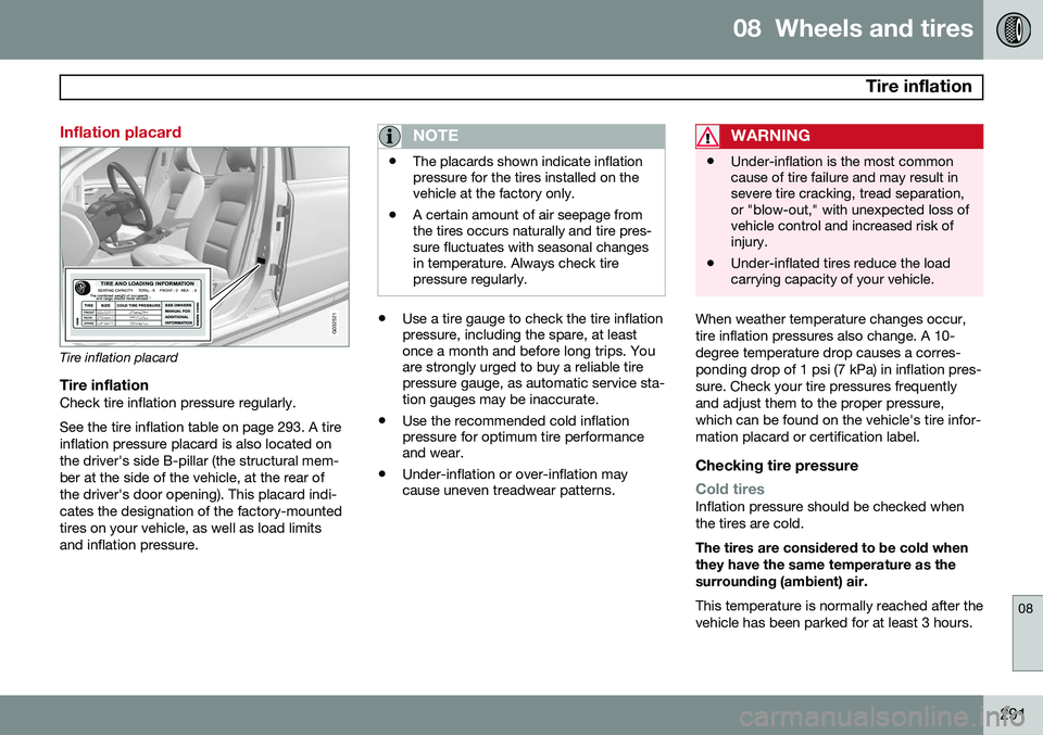
Inflation placard
G032521
Tire inflation placard
Tire inflationCheck tire inflation pressure regularly. See the tire inflation table on page 293. A tire inflation pressure placard is also located onthe driver's side B-pillar (the structural mem-ber at the side of the vehicle, at the rear ofthe driver's door opening). This placard indi-cates the designation of the factory-mountedtires on your vehicle, as well as load limitsand inflation pressure.
NOTE
•The placards shown indicate inflation pressure for the tires installed on thevehicle at the factory only.
• A certain amount of air seepage fromthe tires occurs naturally and tire pres-sure fluctuates with seasonal changesin temperature. Always check tirepressure regularly.
•
Use a tire gauge to check the tire inflation pressure, including the spare, at leastonce a month and before long trips. Youare strongly urged to buy a reliable tirepressure gauge, as automatic service sta-tion gauges may be inaccurate.
• Use the recommended cold inflationpressure for optimum tire performanceand wear.
• Under-inflation or over-inflation maycause uneven treadwear patterns.
WARNING
•Under-inflation is the most common cause of tire failure and may result insevere tire cracking, tread separation,or "blow-out," with unexpected loss ofvehicle control and increased risk ofinjury.
• Under-inflated tires reduce the loadcarrying capacity of your vehicle.
When weather temperature changes occur, tire inflation pressures also change. A 10-degree temperature drop causes a corres-ponding drop of 1 psi (7 kPa) in inflation pres-sure. Check your tire pressures frequentlyand adjust them to the proper pressure,which can be found on the vehicle's tire infor-mation placard or certification label.
Checking tire pressure
Cold tiresInflation pressure should be checked when the tires are cold. The tires are considered to be cold when they have the same temperature as thesurrounding (ambient) air. This temperature is normally reached after the vehicle has been parked for at least 3 hours.
Page 294 of 380
08 Wheels and tires
Tire inflation
08
292
After driving a distance of approximately
1 mile (1.6 km), the tires are considered to behot. If you have to drive farther than this dis-tance to pump your tire(s), check and recordthe tire pressure first and add the appropriateair pressure when you get to the pump. If checking tire pressure when the tire is hot, never "bleed" or reduce air pressure. Thetires are hot from driving and it is normal forpressures to increase above recommendedcold pressures. A hot tire at or below recom-mended cold inflation pressure could be sig-nificantly under-inflated.
To check inflation pressure:1. Remove the cap from the valve on onetire, then firmly press the tire gauge onto the valve.
2. Add air to reach the recommended air pressure.
3. Replace the valve cap.
CAUTION
• After pumping the tires, always reinstall the valve cap to help avoid damage tothe valve from dirt, gravel, etc.
• Use plastic valve caps only. Metal capscould corrode and become difficult toremove.
4. Visually inspect the tires to make sure
there are no nails or other objects embedded that could puncture the tireand cause an air leak.
5. Check the sidewalls to make sure there are no gouges, cuts, bulges or otherirregularities.
6. Repeat this procedure for each tire, including the spare.
NOTE
•If you overfill the tire, release air by pushing on the metal stem in the cen-ter of the valve. Then recheck thepressure with your tire gauge.
• Some spare tires require higher infla-tion pressure than the other tires. Con-sult the tire inflation pressure table onpage 293 or see the inflation pressureplacard.
Tire ratings
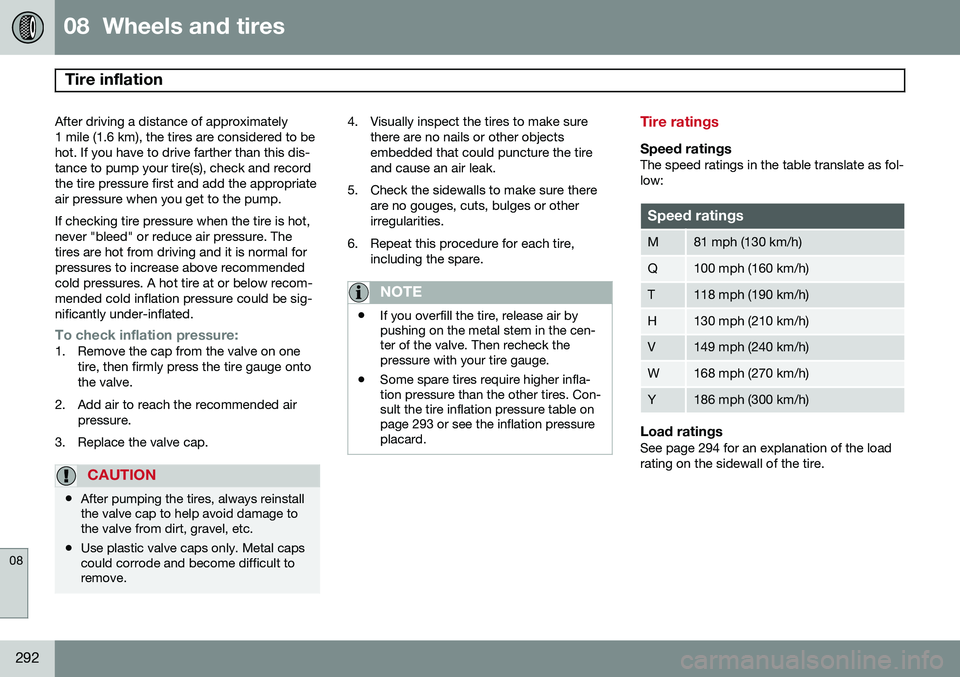
Speed ratingsThe speed ratings in the table translate as fol- low:
Speed ratings
M81 mph (130 km/h)
Q100 mph (160 km/h)
T118 mph (190 km/h)
H130 mph (210 km/h)
V149 mph (240 km/h)
W168 mph (270 km/h)
Y186 mph (300 km/h)
Load ratingsSee page 294 for an explanation of the load rating on the sidewall of the tire.
Page 295 of 380
08 Wheels and tires
Inflation pressure
08
293
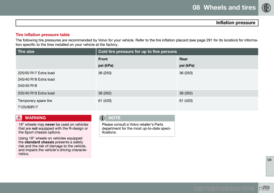
Tire inflation pressure table
The following tire pressures are recommended by Volvo for your vehicle. Refer to the tire inflation placard (see page 291 for its location) for informa- tion specific to the tires installed on your vehicle at the factory.
Tire sizeCold tire pressure for up to five persons
Front psi (kPa)Rear psi (kPa)
225/50 R17 Extra load 245/40 R18 Extra load245/40 R1836 (250)36 (250)
235/40 R19 Extra load38 (262)38 (262)
Temporary spare tire T125/80R1761 (420)61 (420)
WARNING
19” wheels may never be used on vehicles
that are not equipped with the R-design or
the Sport chassis options. Using 19” wheels on vehicles equipped the standard chassis presents a safety
risk and the risk of damage to the vehicle,and impairs the vehicle’s driving characte-ristics.
NOTE
Please consult a Volvo retailer’s Parts department for the most up-to-date speci-fications.